| Pages:
1
2
3 |
XeonTheMGPony
International Hazard
    
Posts: 1640
Registered: 5-1-2016
Member Is Offline
Mood: No Mood
|
|
that makes no sense yobo, you twist the wires to make a short on the end power will go in.
The cap all so should be shunted right up to the point it is connected to the branch/trunk line. Electricity all ways takes the path of least
resistance, steel Vs copper, copper wins so any voltage or current is passed at the ends twisted.
twisted wire ends > cable > Charge to be fired
Definitely need to be care full near such an rf source indeed! Test for current with a multi meter be for wiring the cap to it to ensure no accidents!
Proper way is to hook up the cap, secure the wire then un-spool it as you walk away from the charge again to minimize stray current issues and
mitigate risk should a sufficient current be induced in the spool despite precautions taken, further away you are the less damage you incur to your
self.
[Edited on 31-3-2017 by XeonTheMGPony]
|
|
|
yobbo II
National Hazard
   
Posts: 764
Registered: 28-3-2016
Member Is Offline
Mood: No Mood
|
|
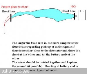
The picture gives my understanding of the thing.
If you are shorting for to stop yourself accidently connecting the battery then you are simply being foolish with the battery/supply. Keep
battery/power supply away.
|
|
|
XeonTheMGPony
International Hazard
    
Posts: 1640
Registered: 5-1-2016
Member Is Offline
Mood: No Mood
|
|
it has nothing to do with the battery, you're understanding is wrong for this!
The whole point of shorting at the battery end is to remove any stray induced currents as you HOOK UP THE CAP!! the electricity will be dissipated at
the shunt.
Putting a short at the cap is as useless as you can get, how do you expect to fire it when it is shorted!
In transport the cap is to be shunted, you then cut the shunt off and wire it to the trunk line.
You then un-spool the trunk line and snip off the shunt, and wire it to your firing box, at this point you are Armed and dangerous, all people should
be cleared befor you cut the shunt!
ANY wire used for the trunk in a firing system should either be parallel strand that is bonded or twisted pair, I use twisted pair as I happened to
have allot of it on hand, but speaker wire or coaxial cable will work as well
https://www.gpo.gov/fdsys/pkg/CFR-2014-title30-vol1/pdf/CFR-...
| Quote: |
726 30 CFR Ch. I (7–1–14 Edition) § 77.1304 (w) Electric detonators of different brands shall not be used in the same round. (x)
Adequate priming shall be em-ployed to guard against misfires, in-creased toxic fumes, and poor perform-ance. (y) Except when being
tested with a blasting galvanometer: (1) Electric detonators shall be kept shunted until they are being connected to the blasting line or
wired into a blasting round. (2) Wired rounds shall be kept shunt-ed until they are being connected to the blasting line. (3) Blasting
lines shall be kept shunt-ed until immediately before blasting. (z) Completely wired rounds shall be tested with a blasting galvanometer
before connections are made to the blasting line. |
There is tons of info on blasting safety and proper blasting procedures, I'd expect any one that is half serious about this hobby to spend a week or
better reading them!
In blasting you F*ck up only once, then they clean you up with a mop!
[Edited on 1-4-2017 by XeonTheMGPony]
|
|
|
greenlight
National Hazard
   
Posts: 754
Registered: 3-11-2014
Member Is Offline
Mood: Energetic
|
|
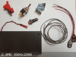
I have purchased most of the parts to make the ignition system. I will start wiring it together in the next few days.
I haven't purchased the lead wires that will run out to the actual igniter yet though as it is going to cost a bit more for that much 14 awg cable.
Can I use a normal electeical shunt to connect up until the wires are to be connected to the control system?
[Edited on 1-4-2017 by greenlight]
Be good, otherwise be good at it 
|
|
|
XeonTheMGPony
International Hazard
    
Posts: 1640
Registered: 5-1-2016
Member Is Offline
Mood: No Mood
|
|
I just twist the ends together, why buy any thing? Looking good so far
|
|
|
yobbo II
National Hazard
   
Posts: 764
Registered: 28-3-2016
Member Is Offline
Mood: No Mood
|
|
I agree with what you are saying.
You should be far away from explosive at the time when all shorts are removed and firing device about to be connected of course.
I am fully aware that you need to remove the shunt from the dedonator!
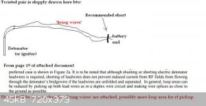
All I am saying is what the picture and document are saying.
It's a bit of a 'red herring' I suppose in the circumstance as you should not be doing stuff in the vincity of power transmitters but be aware they
are all over the place from cb's to door openers etc.
This sort of situation only applies to miltary where rf conditions are bad and you do not get to choose where and when to work.
Use twisted cables or twin cables (as you have said) and do not allow 'loops' to form (places where the forward and return wires are seperated and
above ground) if there is a smell of rf.
Attachment: IMESLP20SafetyGuideforthePreventionofRadioFrequency.pdf (5.3MB)
This file has been downloaded 1005 times
|
|
|
greenlight
National Hazard
   
Posts: 754
Registered: 3-11-2014
Member Is Offline
Mood: Energetic
|
|
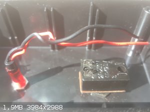
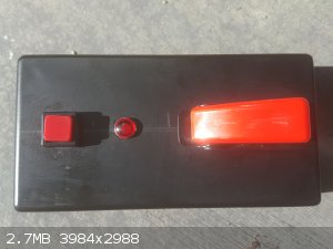
I have the switches installed and it is ready to wire up but I have one question.
In the diagram the safety missile switch has three connections on the bottom for power, acc and ground.
In the picture you can see mine only has two. Where would the acc and ground wires go with two connections?
[Edited on 16-4-2017 by greenlight]
Be good, otherwise be good at it 
|
|
|
XeonTheMGPony
International Hazard
    
Posts: 1640
Registered: 5-1-2016
Member Is Offline
Mood: No Mood
|
|
it is just a single position single throw switch you do not use any other connections.
basically all we are doing is making 2 breaks in the circuit, one protected break that can not be accidentally closed, and one easily closed break.
the toggle switch is the safety break (Hard to close accidentally) normally there'd be a 4.5K resister and an LED shorting the fire button. LED will
glow indicating both power to the firing circuit and circuit continuity yet not enough current to fire the cap, but still placed after the safety
switch to be sure.
you want 1 power led to show the system has power, and the armed warning led indicating continuity and the circuit is live to fire.
for what you are doing the light will hook up to the same pin that goes to the fire push button.
battery + > switch tab 1 > Switch tab 2 (Light + lead) & jumper wire > Push button tab 1 > Push button tab two > Blasting trunk
line connector
Ensure the switch is in the OFF position with the safety latch closed! and rig up a pull pin in order to lift the safety latch for
added security & safety
[Edited on 16-4-2017 by XeonTheMGPony]
|
|
|
XeonTheMGPony
International Hazard
    
Posts: 1640
Registered: 5-1-2016
Member Is Offline
Mood: No Mood
|
|
Clarification!!
2 L.E.D.s one to indicate Armed circuit condition and the L.E.D. indicating continuity, I noticed I worded it poorly making it appear only one l.e.d.
(This is a character fault of simplifying things in a way that make sense to me not others)
Power l.e.d. (Green)
Armed L.E.D. Red
Circuit good orange l.e.d. or red (Orange is preferred to reduce confusion)
This way if 2 out of three light, you know where the fault is and can abort the fire till you test your trunk lines and cap.
You should extensively test your bridge wire and detonator befor it is loaded with any explosives and after final assembly with a digital multimeter
to ensure it's quality long befor it gets out to the site of use.
this is where care full attention to assembly pays off to make them all as consistent as possible, for example all my caps tend to be within 1 to 1.5
Ohms and all most never fall from that range, any that do I classify as defective and destroy.
|
|
|
greenlight
National Hazard
   
Posts: 754
Registered: 3-11-2014
Member Is Offline
Mood: Energetic
|
|
So I should add another led light to show that there is power?
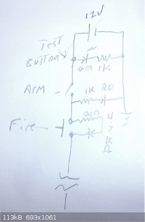
I am still a bit sketchy on the explanation of how it is wired up. Could you draw a simple schematic similar to the initial one if possible with the
added power led in please as that would be a massive help and I will wire it asap.
I will do a lot of testing with igniters and with a voltmeter before I actually use it on a real cap as well.
Thanks Xeon
[Edited on 16-4-2017 by greenlight]
Be good, otherwise be good at it 
|
|
|
XeonTheMGPony
International Hazard
    
Posts: 1640
Registered: 5-1-2016
Member Is Offline
Mood: No Mood
|
|
here ya go, the test for power can be omitted given your circuit design, as it is not very applicable nor use full.
|
|
|
tsathoggua1
Hazard to Others
  
Posts: 335
Registered: 8-1-2017
Location: Beyond the pale
Member Is Offline
Mood: Phosphorescent
|
|
How about using a marx generator and a thin Al foil strip? Or the tantalum foil from a capacitor. Called an exploding bridgewire, or source a
reasonably tough wire from a household low rated fuse, they even have the contacts ready made, would just need the casing of the fuse cracking off,
make sure to have a sufficiently rated diode array to prevent the transient current flow before the wire blows returning to the cap bank. The thinner
the wire, or strip of foil, the less current it will take in order to blow.
|
|
|
greenlight
National Hazard
   
Posts: 754
Registered: 3-11-2014
Member Is Offline
Mood: Energetic
|
|
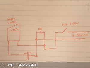
Okay so without the test button and just having a two connection safety switch, LED and fire button would the original diagram look like this?
[Edited on 17-4-2017 by greenlight]
Be good, otherwise be good at it 
|
|
|
XeonTheMGPony
International Hazard
    
Posts: 1640
Registered: 5-1-2016
Member Is Offline
Mood: No Mood
|
|
you need a resister in there or the led would be toast but ya looks correct
|
|
|
greenlight
National Hazard
   
Posts: 754
Registered: 3-11-2014
Member Is Offline
Mood: Energetic
|
|
Okay then I will have to purchase one. Would that be connected right before the LED after the connection that leads to the device?
If the resistor is left out wouldn't the LED just run brighter and have a shorter lifetime?
[Edited on 17-4-2017 by greenlight]
Be good, otherwise be good at it 
|
|
|
XeonTheMGPony
International Hazard
    
Posts: 1640
Registered: 5-1-2016
Member Is Offline
Mood: No Mood
|
|
No the led will instantly burn out
you need a 2K resistor in series with the LED less it has a built in one, then you'll need just a 1 K in series with it.
|
|
|
greenlight
National Hazard
   
Posts: 754
Registered: 3-11-2014
Member Is Offline
Mood: Energetic
|
|
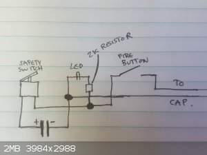
Okay I will go purchase a 2K resistor.
It will go on the positive side of the LED on the right side of it in my diagram like this right?
Thanks for your help just trying to get this right before I wire it.
[Edited on 18-4-2017 by greenlight]
Be good, otherwise be good at it 
|
|
|
XeonTheMGPony
International Hazard
    
Posts: 1640
Registered: 5-1-2016
Member Is Offline
Mood: No Mood
|
|
side really doesn't matter so long as the resister is there.
Now if the led you have is rated for 12v it will have 1 resistor all ready, but double the voltage, you need to double the resistance, so if it has a
built in one, then 1K resister is all that is needed. 2K will work just be a bit dimmer, but will last near forever!
I'm used to dealing with raw components, seems you have some kind of fancy fangled prepackaged unit there!
[Edited on 18-4-2017 by XeonTheMGPony]
|
|
|
greenlight
National Hazard
   
Posts: 754
Registered: 3-11-2014
Member Is Offline
Mood: Energetic
|
|
Yes the LED is rated at 12V. I will purchase a 1K resistor and wire it according to the latest drawing as soon as I can.
Yes everything I have brought is just ready to be connected.
Thanks for your help.
Be good, otherwise be good at it 
|
|
|
CalAm
Harmless

Posts: 28
Registered: 7-7-2016
Location: Australia
Member Is Offline
Mood: No Mood
|
|
Here is another eBook i have found on the hazards of RF frequency's when using electronic blasting caps, published by NC Department Of Labor. (NCDOL)
https://archive.org/details/A_Guide_to_Radio_Frequency_Hazar...
|
|
|
yobbo II
National Hazard
   
Posts: 764
Registered: 28-3-2016
Member Is Offline
Mood: No Mood
|
|
I believe that I read somewhere or other that if you are blasting close to a great big transmitter, that it is actually safer to NOT have a shunt on
the end of the wires of the blasting cap as it is safer to have the wires open. Perhaps a shunt close to the detonator would be OK. (this shunt
removed before firing of course).
This only applies to situations beyond you controll like putting a blast under and enemies radar or transmitting aerial.
You cannot very well request that they should shut it off till you get your job completed.
|
|
|
XeonTheMGPony
International Hazard
    
Posts: 1640
Registered: 5-1-2016
Member Is Offline
Mood: No Mood
|
|
Quote: Originally posted by yobbo II  |
I believe that I read somewhere or other that if you are blasting close to a great big transmitter, that it is actually safer to NOT have a shunt on
the end of the wires of the blasting cap as it is safer to have the wires open. Perhaps a shunt close to the detonator would be OK. (this shunt
removed before firing of course).
This only applies to situations beyond you controll like putting a blast under and enemies radar or transmitting aerial.
You cannot very well request that they should shut it off till you get your job completed. |
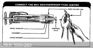
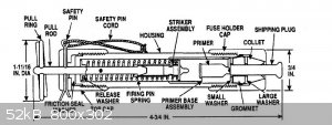
For such demolitions you use safety fuse and a hand firing unit to light it. They are percussion cap based and short of that or a blow torch it does
not ignite! (You can split it to enable easier ignition but the whole point of military fuse is it doesn't go off accidentally)
[Edited on 19-4-2017 by XeonTheMGPony]
|
|
|
XeonTheMGPony
International Hazard
    
Posts: 1640
Registered: 5-1-2016
Member Is Offline
Mood: No Mood
|
|
Figured I'd show you some of the complete cap assemblies I make, the metal one is a 0sec delay, so it goes bang second power hits it, element is
1.75Ohms steel wool
The white ones are paper shelled and where built to accept delays up to 3 seconds! How ever they are set up for 0sec delay.
again steel wool element at apx 1.5 to 2 Ohms, but all ways within that window.
They are primed with some Nitro cotton lacquer, to glue the element on and to protect the metal. you can directly embed it in the primary in loos pack
form
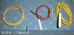
Please note how the wires are either twisted or parallel bonded
500mg base charge with 300mg HMTD booster, for the small metal cap it is fulminated mercury 80%/ potassium chlorate 20% at 150mg
So at 6V = 6^2/1.7ohms = 21w of thermal energy dumped into the bridge wire! at 12V = (12^2)/1.7 = 84w! So we can see that keeping the resistance down
we get much better energy dumped into heat to the wire. Steel does not hold heat well so it tends to glow white hot easily!
try several metals on a 9v 
Tungsten wire is great, but for the hobby level next best thing imo is all ways steel wool, NiChrom is much more valuable for making heaters with!
[Edited on 22-4-2017 by XeonTheMGPony]
|
|
|
Hennig Brand
International Hazard
    
Posts: 1284
Registered: 7-6-2009
Member Is Offline
Mood: No Mood
|
|
I too have used steel wool as a resistive/heater element with great success, but once I got a 1/4lb spool of 40 gauge Nichrome wire I never went back.
The quarter pound of Nichrome wire that fine will last me a lifetime and it cost me less than $60 (had a friend with industrial supply connections).
It is much more corrosion resistant, it has extremely consistent and uniform cross sectional area (steel wool is normally very inconsistent), its
electrical resistance changes only slightly with temperature until phase change of course. This is not an area I would cheap out, unless it was
necessary in an improvisational type situation.
The military firing boxes I have seen for flares etc, had two toggle switches. The arming switch had a cover which had to be lifted to access the
arming toggle switch. The firing toggle switch was a momentary switch with a strong spring return mechanism, which would only go to the firing
position with a very deliberate push and then return to the no fire position once force was released. Both switches had associated lights mounted
above them. I have two or three of these boxes, retrieved from old military vehicles, but I haven't looked at them in a couple of years. The switches
were high quality steel toggle switches with rubber seals/boots to keep moisture out all housed in a very sturdy metal enclosure.
"A risk-free world is a very dull world, one from which we are apt to learn little of consequence." -Geerat Vermeij
|
|
|
greenlight
National Hazard
   
Posts: 754
Registered: 3-11-2014
Member Is Offline
Mood: Energetic
|
|
I think I will definitely use steel wool instead of nichrome for the electric caps.
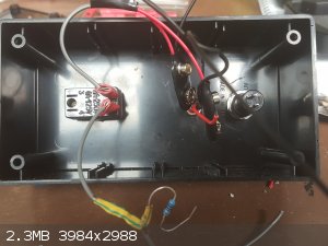
I have wired some of the control box up and have gotten up to the led but I am still stuck on the cables to run out to the actual device.
I went and asked for a price at an electonics shop for 40 metres of 14 gauge wire and its is $108 for that much! It also looks a lot thicker than the
stuff in your photo you uploaded of your dets.
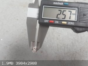
I think awg is different somehow from standard gauge.
It says awg is 1.63mm thick in diameter and this stuff was way thicker.
I went to a hardware store and found some wire that looks more like it would suit the whole setup better. It is in the second photo with a vernier
caliper measurement included. Would this work as it is much cheaper per metre and would probably cost $30 for 40 metres?
I could find smaller gauge wire with diamter closer to 1.63mm if needed.
[Edited on 24-4-2017 by greenlight]
[Edited on 24-4-2017 by greenlight]
Be good, otherwise be good at it 
|
|
|
| Pages:
1
2
3 |