| Pages:
1
..
3
4
5
6
7
8 |
1281371269
Hazard to Others
  
Posts: 312
Registered: 15-5-2009
Member Is Offline
|
|
I really can't thank you enough for your post peach, it's fantastic.
I have a very basic knowledge of electronics (AS physics, building a usb throttle quadrant, wiring plugs) but the stuff about capacitors and those
wiring diagrams sort of scared me. I'll read over what you've written a couple of times and then try starting the pump up.
I've tested the no.1 push fit fitting with my multimeter - there's no connection at all between it and the L plate. The no.2 slot doesn't appear to
have any metal inside it at all. Perhaps they're for some sort of monitoring device?
I'll definitely use an RCB and a 3A fuse - thanks for the advice
Rather than crimping the service pipe, how about attaching an adjustable air bleed to it?
|
|
|
peach
Bon Vivant
    
Posts: 1428
Registered: 14-11-2008
Member Is Offline
Mood: No Mood
|
|
I remember being in AS physics and someone had discovered they could generate sparks by shorting the Unilab (orange and brown) bench supplies out. The
teacher quietly walked over to point out that, whilst it was 12Vdc, the supply was plugged into the mains.
Another funny one, although in the GCSEs, was watching one of the guys who was about to leave igniting the gas taps. Again, he didn't realise the
teacher was stood literally a foot behind him, facing him.
With regards to testing the 1 and 2 fittings, I suspect they are connected to something somewhere on the pump it's self, as there'd be little point to
them otherwise. Touch one probe against it and then go over every other metal contact on the pump and see if there's a zero or low resistance reading
for any of it, including the casing (you'll need to touch it against the tubing to get a good contact for that).
Before you ever use a multimeter, set it to resistance and try touching the problems together first to check the thing is actually working. This is
particularly important if you're about to check if the mains circuit you're going to be fingering is dead.
I've had a really nice Fluke 123. Those things are absolutely beautiful, and also extremely expensive and excessive for a lot of work. One nice
feature of it (amongst the arsenal of others) was that it'd beep on continuity checks. I had to sell that, to cover university debt, and now have a
£5 analogue one from Toolstation. An annoying, and potentially lethal, feature of this one is that the probe connections will disconnect themselves
mid work, but remain in the holes. Which means it needs checking every single time I'm making a new check on a different, possibly live, wire.
If you place you're multimeter probes across the two contacts I've labelled as live and neutral, you will likely measure a small resistance; which is
the winding inside the pump.
You could attach an air bleed to the spare service pipe yes.
The only thing you may want to consider when bleeding gas in is what it will do in terms of the flammability of the things inside the pump. All fuels
have an ignition band, the ratio of fuel to oxygen needed. If the fuel is very dilute, it won't ignite. If it's very concentrated, it won't ignite. If
the pressure is very low, it won't support stable combustion. By bleeding air in, you may create a good mix for ignition.
In the US, people have air conditioners to cool their house. The 'fridge' is mounted outside and pipe work carries the refrigerant to the grills
inside. These are full of flammable gas. The conditioners sometimes need recharging. The system is put under vacuum to remove any moisture,
contaminated refrigerant and oxygen before the new gas goes in. They get very upset when they have home owners doing it half arsed on their forums,
due to the potential for it to incinerate the house.
With these pumps, without bleeding air in, even if the exhaust caught fire as a solvent went through, it'd only burn outside of the pump, where
there's oxygen and where it's being pushed to by the pump. It could possibly be more dangerous bleed atmosphere into the casing, where the mixture
would be in a sealed system.
It depends entirely on what you're putting through it in the first place. And, given the lack of any brushes inside the motor, sparks aren't a likely
possibility. That leaves the only source of ignition as hot surfaces. For something to ignite without a spark, it has to be mixed with oxygen in the
ignition band and reach it's autoignition temperature. The lowest of those, for a solvent you're likely to come into contact with, is diethyl ether,
at 160C; and the heads of the pumps don't get much hotter than 50,60,70C. Carbon Disulphide will go at 90C, but that is a fairly odd solvent to have
at home.
There is a long list of them here, and you can see they're all in the hundreds***
To give you an example of why the semiconductor people end up spending a fortune on their stuff, one of the things they routinely use is Silane (the
silicon analogue of methane), which will autoignite at room temperature.
If one of the electronics guys, who can build VFD's and program microcontrollers, was feeling the urge, they could even make a little controller to
spool the motor of the pump it's self. That could be used to regulate pressure without having to bleed gas in.
You could do that with a variable transformer, or an off the shelf VFD drive, but those would require manually adjusting. What's be neat about doing
it with a microcontroller would be you could then have the pump spool to the correct pressure for the solvent and condenser type / temperature you're
using.
Buchi make controllers and pumps like this. Needless to say, the price is eye watering.
I have tried three or more times to get my microcontroller on, but am never happy when the guides simply say "Type this... it will make this flash".
I'm always left thinking... "There's stuff happening here that isn't being explained". BUT... I WILL get it on, they and FPGA's are far too useful to
simply ignore.
***Autoignition and flashpoint are two different properties. The flashpoint is the temperature a material will form a flammable mixture with the air
at, but it needs a spark to ignite it. The autoignition is the temperature something will ignite at without a spark present.
[Edited on 6-2-2011 by peach]
|
|
|
1281371269
Hazard to Others
  
Posts: 312
Registered: 15-5-2009
Member Is Offline
|
|
The most stupid thing I've done in school science lessons was to put some calcium carbonate in the 5L container of molar HCl during a GCSE chem
experiment. I guess luckily, our teacher noticed before the gas pressure had built up too much and had a major go at the class. I'm now doing A2 and
have a very relaxed and friendly relationship with the same teacher, but I still haven't had the heart to tell him it was me.
Bad news with the pump: wired it up and earthed it (connected the live wire to the 'L' side and the blue to the 'N' side) with a 3A fuse and an RCB.
Tested the RCB, flicked on the mains switch, and...nothing :|.
I guess I've missed something in the wiring, because the fuse wasn't blown and the RCB didn't flick off. I also tested everything else beforehand for
good connection (multimeter, fuse, plug, cabling).
Perhaps I need some sort of connection across the starter?
|
|
|
peach
Bon Vivant
    
Posts: 1428
Registered: 14-11-2008
Member Is Offline
Mood: No Mood
|
|
Did the pump hum at all?
Some of the older ones do need a starting capacitor, but they can hum without one. The capacitor is there to provide a pulse of energy to help get the
motor spinning. The newer pumps tend not to need one.
It's also possible one of those other connections went off to the thermostat. Well, it's not possible, it WILL have.
That means there will be a block on there where the mains comes in and goes off to the thermostat, and another which comes back and connects the live
to the motor when the thermostat says it time to cool the fridge.
Try measuring the resistance between the two I've marked live and neutral. If it reads a high resistance, an open circuit, it's unlikely those are
directly connected to the motor.
You will need to have a poke around until you find one that doesn't read zero to the case, but does read a low resistance. Those two should be the
ones for the windings.
I have seen this happen myself, where two contacts need shorting to start the pump. Usually, it's not too difficult to find those if you're pulling it
out of a fridge, as you can see where the thermostat used to connect.
[Edited on 6-2-2011 by peach]
|
|
|
peach
Bon Vivant
    
Posts: 1428
Registered: 14-11-2008
Member Is Offline
Mood: No Mood
|
|
I will give you a head start, I suspect it may be the one I've labelled as 1. I'm not sure what you mean by L plate, if you mean the thing I've
labelled as live or not.
Failing that, it's the pink / purple one, but I can't see if that's actually a spade terminal from the angle of the photo.
The only others are the ones I've circled in green and yellow, but they don't look like they're actually connected to the relay and pins.
|
|
|
1281371269
Hazard to Others
  
Posts: 312
Registered: 15-5-2009
Member Is Offline
|
|
Nope, no hum.
The resistance between the live and neutral is above even the 2Mohm reading. No suggestion of a connection between them at all, even.
None of the obvious connections give a show continuity between the case (I used the earth connection) other than the three outlets.
I also retested the no.1 push fit and I do get a reading of continuity between it and both the metal on the relay and the neutral connection. Both
have a low resistance of about 20ohms.
|
|
|
1281371269
Hazard to Others
  
Posts: 312
Registered: 15-5-2009
Member Is Offline
|
|
Green and yellow are definitely earth - I noticed the earth symbol on the plastic and they are both attached to the casing.
Sorry - 'L' meant live (there's an L in the plastic next to the connection)
|
|
|
peach
Bon Vivant
    
Posts: 1428
Registered: 14-11-2008
Member Is Offline
Mood: No Mood
|
|
I have just edited the post on the other page, having noticed I've been calling it a starting relay when it's not, it's the overload switch for the
motor.
That aside!
If the terminal labelled 1 is showing about 200 ohms to the neutral block, that is likely the point at which the live returns from the thermostat to
the motor.
{edit}Now that you've established the green and yellows are the earths, that doesn't leave a lot left.
[Edited on 6-2-2011 by peach]
|
|
|
1281371269
Hazard to Others
  
Posts: 312
Registered: 15-5-2009
Member Is Offline
|
|
I tried attaching the live to terminal 1 with the other connections the same - again, nothing, not even a hum
|
|
|
1281371269
Hazard to Others
  
Posts: 312
Registered: 15-5-2009
Member Is Offline
|
|
Sod that...it blew the fuse.
I replaced it with a 5A one though, which didn't go, nor did I get any sign of life.
I tried again with brown attached to the piece of metal on the overload switch. This time I got a hum and a vibration, but I didn't notice any
airflow. Switched it off fairly quickly though, in case I was frying it.
[Edited on 6-2-2011 by Mossydie]
|
|
|
peach
Bon Vivant
    
Posts: 1428
Registered: 14-11-2008
Member Is Offline
Mood: No Mood
|
|
I'm beginning to wonder if that switch may need adjusting.
The fact the compressor hums when you touch the live directly to it, but doesn't when it's connected to the remaining terminals, suggests it may be in
a permanently open state at the moment.
You could try connecting the live back to the terminal marked 1 and then adjusting the screw on the switch. Be careful with it live on the mains as
you do this. You really want screw drivers with insulated blades for doing that kind of thing.
[Edited on 6-2-2011 by peach]
|
|
|
1281371269
Hazard to Others
  
Posts: 312
Registered: 15-5-2009
Member Is Offline
|
|
The screw is pretty difficult to move. It doesn't have a normal head, it just ends in a flat piece of metal and I'm having trouble budging it even
with pliers.
I've noticed that on the motor there are three marked points (labelled 1, 2 and 3). 1 and 2 are metal connections, 3 seems to just be a raised piece
of black plastic. 1 was the bit I was attaching the live to before to get a hum. 1 shows continuity with 2, and with the screw in the middle.
I tried attaching the live to 2. Sparks, but nothing. And now nothing when I put it on 1, either, which is worrying - didn't blow the fuse. The whole
overload is also noticeably warm. I have a feeling I've blown it...perhaps I'd be better off removing the whole assembly to reveal the three prongs,
and start from there?
Doing some more tinkering:
The whole unit easily slides away to reveal the three prongs.
Removing the plastic cover on the back of the unit reveals that the live input isn't connected to anything at all - so it would definitely go through
something else before returning to the pump.
Disconnected from the prongs, there is no continuity between the overload and either the push fit (no.1) input or the neutral. The continuity I got
before was reading through the motor.
There is continuity between the push fit input and the neutral (low resistance) explaining why I blew the fuse before - the circuit was presumably
shorting across the two.
There is also continuity between the 1 and 2 connections on the overload.
Finally, I noticed the statement on the side of the pump 'no start without starting device' - perhaps something I'm missing?
Not much else I can think of, really....
Thanks again for the help, peach. It's been fantastic, even if I haven't got the bloody thing running.
[Edited on 6-2-2011 by Mossydie]
|
|
|
peach
Bon Vivant
    
Posts: 1428
Registered: 14-11-2008
Member Is Offline
Mood: No Mood
|
|
My contacts are gluing themselves to my eyes! Don't give up yet, I doubt you've ruined it.
Having scrolled through the PDF and searched around for a good while, I've discovered the P in the code on the side of compressors standards for "PTC
+ Run Capacitor (optional)"
The PTC is a disc of material, it's called a Positive Thermal Coefficient relay. When it's cold, it has a very low resistance and will energise the
start winding. It almost instantly warms up, the resistance rises, and it disconnects the starter winding - largely.
Here's a picture of one, it's the cylinder in the centre.

Here's the assembly off the side of one of the pumps I have. You can see inside the overload switch, although a piece of it is missing. The thing
below it, the thin cylinder, is this one's PTC.

If I flip it over... you can see the PTC is sitting a bump sticking out the plastic moulding. This may be what the plastic bump is in yours between
the two blocks I've labelled as live and neutral. Which suggests you have the PTC it needs.
You can see I also have some spare starting capacitors, if you find you need one you can have it for the postage.

The rest of the code standards for Embraco Mini Compressor, 2nd generation, R-600a refrigerant, Low Back Pressure, PTC + Run Capacitor (optional)
This band of units, it appears, are low starting torque units. Not only does the P code say the RUN capacitor is option, it states that is a START
capacitor is mandatory for others. All that suggests you don't NEED any form of capacitor.
The question is now where to connect the live and neutral connect. Scrolling through the schematics, only two of them use a PTC, and only one of them
is for the EM line - on page 23, the top left schematic.
The mains goes to pin 3 on the OVERLOAD switch, and pin 2 on the PTC.
I can see a pin marked 3 on the overload.
The PTC looks nothing like the circuit schematic drawing, and I can't see any numbers in the photo. Can you have a closer look at it in person and see
if you can find any more numbers.
Are pins 2 and 3 on the overload switch even separate spade connections, or connectors?
In the meantime... here are some top trump factors for your compressor!
It has a 5.19 cubic centimetre displacement, a 64W heat moving capacity, a 0.98 Co-efficient Of Performance and is using ester based oil.
Curious, because further up the PDF it says the R-600a's use alkylbenzene and mineral naphthenic. The letter L in the code on the casing is also not
used in the EM range of codes, yet the compressor clearly belongs to the EM range.
Have a GOOD look over the other terminals for some more numbers. If there is a spade connection on pin 3 of the overload switch, that should be one
point for the mains.
On the PTC, that looks nothing like the schematic drawing of it. There is only one point the mains needs to connect to on the PTC, and I think it may
be the one I've labelled as 1. Again, check for numbers around there.
Also, try sticking the multimeter on pin 3 of the overload switch, and then the pin I've labelled as 1. In the schematic, if these are the two pins
they're on about, that should have a motor winding and the PTC between it. Which should give a low resistance reading, but one more than zero.
[Edited on 6-2-2011 by peach]
|
|
|
peach
Bon Vivant
    
Posts: 1428
Registered: 14-11-2008
Member Is Offline
Mood: No Mood
|
|
Quote: Originally posted by IrC  | I think you guys are wasting your time using these pumps unless you are looking for a distillation setup or a roughing pump.
[snip]
For a decent laser you need to get down to say 60 microns or lower.
|
Indeed.
However this is primarily a chemistry forum, as opposed to physics, so I assumed most people would be more interested in filtration, distillation and
vacuum drying.
And your point about the cheap rotaries is one I made myself in the video. But quite a lot of people here also have next to zero money to spend on
individual parts when they need so many different, and equally expensive, things for at home science. It is there hobby, they make no money out of it,
a good number of them are young (which also means not particularly good money wise) and, since they're interested in science, they will be in for a
rough ride when it comes to paying for the rest of their education.
I'm not messing people around when I say I still use fridge compressors for chemistry. In fact, I use them most of the time and one of them is running
right now.
This is not because I can't produce a higher vacuum, there are other factors at work.
A lot of the fun of doing science at home for me is trying to see how little I can get away with using to produce the same result. In the case of
vacuums, it goes further in that, if you connect a rotary to a volatile solvent, without a dry ice or liquid nitrogen trap, it's going through to the
pump.
There is also a reasonable possibility that the pressure these pumps can achieve can be lowered. It's just that I haven't got round to checking all of
the ideas yet. Pfeiffer have managed <0.1mBar with piston layouts; with 0.1mBar being 75 microns.
It's worth remembering that a lot of the poorest people in the world, who can't afford a physics lab vacuum pump, also have access to piles of fridges
and freezers. It's quite likely the progress of science in these areas is being blocked by things like... them not being able to get a pump to do a
filtration or to pull a flash column. The wider spread the information is, the better.
In terms of those people being stupid or too cheap to spend money when it's needed, I have seen more than one chemistry blog online by someone who has
a PhD who is also connecting solvent boil offs to high vacuum lines, and then complaining about it getting through the trap.
Also, in more than one example, their solution was to simply throw more and more money at it rather than swap the vacuum source to something more
suitable. We should not be blindly throwing tens of thousands of pounds at boiling a solvent when it can be done with something from the tip and
tuition fees are having to be tripled, effective immediately.


[Edited on 6-2-2011 by peach]
|
|
|
aonomus
Hazard to Others
  
Posts: 361
Registered: 18-10-2009
Location: Toronto, Canada
Member Is Offline
Mood: Refluxing
|
|
| Quote: | | Buchi make controllers and pumps like this. Needless to say, the price is eye watering. |
These controllers usually go on 10-20L preparatory rotovaps like the ones they make. I happen to use these on semi-frequent occasion as well. Its
neat, the pumps are all inert with teflon/glass innards and the motor will run at high speed until reaching the rough set point, where the motor spins
down and it can even execute individual pump strokes to maintain the pressure within +/- 1 torr ripple.
|
|
|
Regolith
Hazard to Self
 
Posts: 73
Registered: 4-2-2011
Location: Mining the moon.
Member Is Offline
Mood: Glacial
|
|
Greetings all, It's been several years since the days of the E&W forums. Having looked around and found a source of rogue research lacking in my
life. I've decided to crawl back out from the rock I was quite comfortable living under.
My father before me was/is a journeyman appliance repairman. I took up his mantle adding several sciences and computer technician to the list. I
figured a first post here squarely in my back yard was a good choice.
Peach, Kudos for taking a compressor. They are soo not intended for open (but can be repaired once open) maintenance as you have well now discovered.
Also congrats on a similar pile of old tech to my own if the pictures are indeed your house. I saw large old caps and what appeared to be a large
toroid transformer in the piles behind the pictures. It needs about a dozen MOTs and random glassware scattered about and it would be home. OH I also
understand your pain at kissing goodbye a fluke123 I had one and turned it in because i needed a feature it was lacking, can't member what... Anyway a
uni-T ut55 and a Fluke Pv350 fills the void, with less void in my wallet mind you.
Mossydie, you pretty much can't kill the compressor by wiring it wrong, the windings for example are already just a short across the terminals with a
couple hundred feet of motor windings between them and having 2 mains wires on the same terminal will simply blow your breaker(also a good suggestion
Peach). More likely whats happened since its a brand new compressor is it's become frozen in its state. The oil used isn't exactly top shelf and it
can cause parts to adhere if left for long periods of time. Warming the entire unit up maybe an option as would a start capacitor. Your idea of
removing the whole plastic housing crap is what I would do to get to the bottom of this. the 3 exposed terminals can be wired to directly and in fact
a commercial start cap has special spade connectors that also fit tightly on the round pins of the compressor housing.
Pictures really are worth a thousand words can you take more of the plastic POS and the compressor itself the 3 pins (on the housing itself) will be
marked either with numbers or better yet, letters. Often that plastic housing has bi-mettalic straps or likewise to pull the connector pins away from
the connection with the compressor housing(once started). Hence the reason the commercial starter repairs are designed to fit right onto the pins.
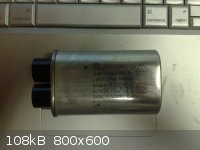
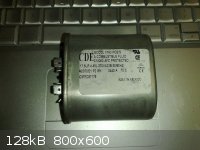
I've attached a couple pictures of start caps there cheap like 10 bucks cheap. The high voltage one is usually what comes in a microwave. It was sold
to me at my usual parts watering hole as a start cap but my own experience tells me otherwise (that and the only 2k voltage rating you will find in a
house is your microwave, or a CRT tube but that doesn't need a start cap). A 10 MegOhm resistor is inside it and will discharge the cap under normal
power down circumstances.
The second big chunky guy is more like it 17.5 MicroFarads and 370 volts 50 or 60hz , universal no matter which side of the pond your on.
Finally I don't understand the haters for these machines. A more lowly appliance doesn't exist and yet your simple fridge compressor can heave over a
1000 psi and draw vacuum in excess of -27 inches of Hg. A scrapped fridge and 100 bucks of ebay glassware lets you distill anhydrous nitric acid. What
on earth is there to complain about ? It doesn't grant wishes and offer sexual favours?
|
|
|
1281371269
Hazard to Others
  
Posts: 312
Registered: 15-5-2009
Member Is Offline
|
|
Here are three labelled pictures of all the connections I can find:
The pins with the unit removed
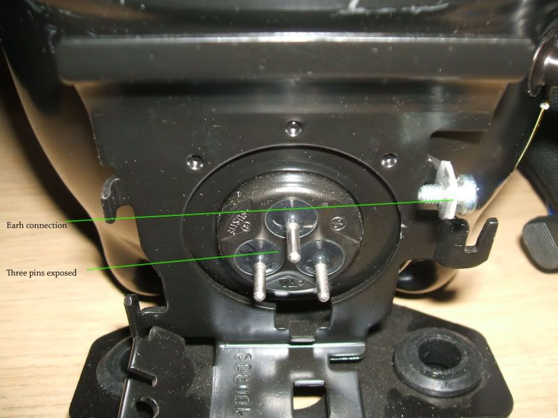
The front of the unit

The back of the unit

The resistance between the push fit connection and the neutral connection on the front (when the unit is removed from the pins) is almost identical to
the resistance between the lower two sockets for the pins - so I'm guessing this is actually a measure of the resistance of the pcb when cold.
I tried connection the mains a different way: neutral to neutral, live to the piece of metal I've labelled as suspected 'pcb connection'. I got a
similar vibration and humming but no obvious movement of air.
There is a number three on the overload switch, but it's next to just a raised bit of plastic. I though it might refer to the metal connection
underneath the overload ('pcb connection')?
[Edited on 6-2-2011 by Mossydie]
|
|
|
Regolith
Hazard to Self
 
Posts: 73
Registered: 4-2-2011
Location: Mining the moon.
Member Is Offline
Mood: Glacial
|
|
Excellent, Of the 3 pins top is common left is start right is run(you have a normal hermetic compressor, nothing oddball about it). Put the plastic
back on the motor and connect your Live to the pin coming from the overload connector 1 (which I believe is actually pin 3 on the diagram and thus the
correct connection) and the neutral to the obvious. Problem is as mentioned it's one single chunk of plastic and they have made it for many models
thus the trouble...
Erm odd question you have all the plastic caps off the copper right, if you have noise there should be air movement, it's not gonna be an airbrush on
its own the air movement may be difficult to detect the vacuum however is usually pretty obvious, sticks fingers etc to the intake.
Something else occurred to me after the fact, once you have known good pins running noise/vibration you may want to try this without the fuse. Reason
being while a compressor doesn't take much to be running the start surge can be significant and without this surge the compressor sometimes wont run
correctly, hence the need on larger models for a start cap and yet low amp draw on the nameplate.
Btw as mentioned on here these things DO get murderously hot which is why you want the thermal protection in place they can exceed 160C right on the
housing. They are built for it, keep the stock thermal in contact the way it should be and sleep well knowing it shouldn't burst into flames in the
night if your running it unattended(you should never do that btw, unless your distilling WATER under vacuum all night never leave a project
unattended).
Side-note, in case you are curious why the live isn't connected to anything. It functions as a connector bridge if your adding start caps, thermal
overloads etc. From the factory this unit IN something this would have likely had an 3cm double female spade connector bridging the thermal to the
Line allowing the use of the screw-downs for attaching bare wire to the terminals.
[Edited on 6-2-2011 by Regolith]
|
|
|
1281371269
Hazard to Others
  
Posts: 312
Registered: 15-5-2009
Member Is Offline
|
|
Erm...nope, the caps were still in *leaves forum in shame and never has the guts to return*
I didn't actually realise that they were blocking the airflow - I thought they were some sort of connection fitting.
With that wiring, it's working very nicely. Please accept my most sincere apologies peach! If there's anything I can do to make it up...
Anyway, I suppose what counts is that it's working. I owe a huge thanks to you and regolith for helping me with this.
Incidentally, is it worth changing the oil? I know the ester stuff can be problematic because of its reaction with water.
[Edited on 6-2-2011 by Mossydie]
|
|
|
peach
Bon Vivant
    
Posts: 1428
Registered: 14-11-2008
Member Is Offline
Mood: No Mood
|
|
Quote: Originally posted by Regolith  | | OH I also understand your pain at kissing goodbye a fluke123 I had one and turned it in because i needed a feature it was lacking, can't member
what... |
Let us both have a moments silence as we remember, those good times with the 123.
Press the green button... click... nice...
I wanted the thermocouple for mine. I actually had two, because I sold one, then found I needed it for something, so bought another and then sold that
as well.
The second one had the FlukeScope optical isolation lead and software, which only made it even more bad ass!
At the same time, I found myself thinking, this is without question the best multimeter on the planet, yet the scope isn't all that great. But then, a
scope of the same price probably isn't going to have the multimeter functions the 123 has.
I can appreciate how someone who works in industry, wandering around plants, would love having so much in one thing that can be put back in the bag,
and wouldn't be too bothered about the lack of detail on the scope so long as they could spot some triggering glitch and report it.
The big capacitors are part of some 30 amp linear regulators. There are indeed toroidal transformers, MOTs and magnetrons on the desk. I have tons of
photos of my glassware and other things on my facebook page. I'll send you a link in a second if you want to troll through some nerd porn.


Quote: Originally posted by aonomus  | | Quote: | | Buchi make controllers and pumps like this. Needless to say, the price is eye watering. |
These controllers usually go on 10-20L preparatory rotovaps like the ones they make. I happen to use these on semi-frequent occasion as well. Its
neat, the pumps are all inert with teflon/glass innards and the motor will run at high speed until reaching the rough set point, where the motor spins
down and it can even execute individual pump strokes to maintain the pressure within +/- 1 torr ripple. |
I'm sure I know someone who can program microcontrollers on here... just trying to remember... who.... 
The problem more like!
I was standing in the kitchen at 4am thinking, maybe he's left the caps on, and thought.. "Nah... he's not left the caps on". 
Never mind! So long as it's working, it's good.
The little puck shaped thing isn't a PCB, it's a PTC, a thermistor which changes it's resistance based on it's temperature.
In this case, it's starts off with a low resistance, a big surge of current goes through when the mains is applied, it warms up and it effectively
switches off the circuit it's connected to by putting a big amount of resistance in the way. So it's normal for them to warm up.
PTC is actually telling you the type of thermistor, that it has a positive temperature coefficient.
There is an opposite to that, called the NTC (negative temperature coefficient).
They get used to prevent surges. Say you have a lot of capacitance in a power supply, straight after the transformer and rectifier
(almost directly on the mains), as soon as the supply is plugged in, the capacitors look like a near perfect short circuit until they're charged up.
You can add NTC's to the supply which block the instant surge and only let the supply function at it's maximum current once they've warmed up.
Those power supplies above do it. They have zero form of surge protection, but have very large capacitors pretty much directly on the mains. If I plug
them into a normal ring socket, they'll trip the breaker. They have to go on the cooker socket, the cable and breaker for which is designed to handle
three to four times more than a ring mains. It's one thick cable, directly from the breaker board. The only other such line you'll find in a house is
for an electric shower. Both are extremely dangerous in terms of shocks and fires, and subject to special notice in the Part P regulations of the
building codes.
In terms of changing the oil, someone on the last page mentioned Silicone oil. The things to consider in terms of changing the oil are;
a.) will it decompose when contaminants get through and
b.) what is it's vapour pressure
Vacuum pump oils need to have a low vapour pressure, or they'll start counteracting the effect of the pump by releasing gas of their own. Silicone is
used in diffusion pumps, where the oil is going to be heated, encouraging vapour pressure problems.
Quite a common theme with low vapour pressure oils is that they typically have a higher boiling point and, more importantly for us, they are usually
thicker!
The thicker the oil is, the more energy the pump has to put into churning it. As I say earlier on in the thread, I have tried replacing the oil in one
of these with actual rotary pump oil and, without checking it with the thermometer, I seem to remember it was running a bit hotter with it in place.
It had gone from a normal cup of coffee temperature to one that's just come out the kettle, so perhaps 10-20C hotter.
Using thicker oils, I would recommend you think about sticking a computer fan to the top of the pump. I doubt it'll overheat without one, but running
the pump a little cooler will improve the vacuum and make it less likely to seize.
I've never had a single fridge compressor stop working in the middle of something. The one I have switched on now has been on for over two days, and
it's still running.
If they're going to seize, it's when you switch it off. As the metal inside has warmed up, expanded and needs a little time to cool down. It's a good
idea to leave the pump running all the time as you work, rather than switching it on and off and risking it needing time to cool down when you need to
do something quickly.
[Edited on 7-2-2011 by peach]
|
|
|
1281371269
Hazard to Others
  
Posts: 312
Registered: 15-5-2009
Member Is Offline
|
|
Gah, 'PCB' was a slip, I knew it was called a PTC because I looked over the circuit diagrams last night and googled the term. Thanks for the info
about them though, it's interesting stuff.
I'm not sure about the oil. I don't need a higher vacuum than the one it pulls already (main uses will be filtration, possibly a reduced pressure
distillation or two), so my concern was about hydrolysis. But it should be easy enough to stop water getting in with a cold trap / conc. H2SO4.
Thanks for the advice about the fan, I'll rig something up. Considering the average temperature of my lab at the moment though, anything being too
warm is pretty much impossible.
I did a great test just now with DCM: put a small amount in a flask then applied vacuum. It very quickly started to evaporate and then to boil
(extremely bumpy). There had also been some water droplets in the flask before which formed a layer of ice around the edge of the DCM. Very cool.
[Edited on 6-2-2011 by Mossydie]
|
|
|
peach
Bon Vivant
    
Posts: 1428
Registered: 14-11-2008
Member Is Offline
Mood: No Mood
|
|
The only real reason for wanting a higher vacuum is for distillation of oils, which tend to boil closer to 300C at room temperature.
Ideally, you shouldn't be running borosilicate glassware, or organic chemistry, over 250C. Once it starts getting toward 4 and 5 hundred, you can fix
strain in borosilicate glass. There are more issues as well;
1.) Most common thermometers, even mercury ones, reach their limit around 250 to 300C. A lot of them are below 200C.
2.) Roasting the ass out sensitive organic compounded will cause them to either react with something in the remaining atmosphere or thermally
decomposed / rearrange
3.) Normal keck clips melt around 125C, and PTFE ones start going over 250C (and releasing HF fumes)
With a fridge pump as it is, you can get the temperature of those distillations down to about 150->175C. But it would be nice if they could squeeze
the temperature down a bit more without having to do much to the pump. As an example, if the pumps could reach 1mBar, that'd mean the distillation
could run around 110C. A deeper vacuum is also good for getting salts really thoroughly dried when they'd react or decompose in a
normal atmosphere. You can, however, still dry a lot of things with the pumps as they are.
I'm beginning to enjoy this nasty weather we're having. I too do experiments out in the garage, where there's no heating, and the near freezing
temperature certainly does make condensing things a lot easier.
I do not think your fridge pump is going to have problems with overheating as it is. I have actually stuck data-logging thermometers on the pump heads
and left them going for hours, and the temperature stabilises somewhere around 50 to 70C from memory. I have never seen one come close to getting hot
enough to boil water, which means they are well below 100C. And I have certainly spent enough time over the last decade running them for 12h+ each go
to be confident in that.
DCM has a particularly low boiling point, even when compared with the other volatile solvents, making it difficult to condense anywhere close to 100%
of it if it's being distilled under vacuum and the condenser isn't being run from an ice slush.
It's BP is so low (40C), I've thought about distilling it directly out of the metal cans paint stripper comes in rather than getting it on my glass.
To put it into perspective, the radiators in my house are at 45C, so it would boil off if I simply sat the can on top of one.
The best forms of cold traps, at present, for a vacuum pump are dry ice and liquid nitrogen. Both of which are far harder to find in small quantities
in the UK than they are in the US. But, I rarely ever, in fact never, see anyone on here from the US using them either.
If you put a H2SO4 trap before the pump, you will want to have an empty trap after that and preferably something filled with activated carbon after
that.
The first empty container is needed because there's a high chance that you will end up sucking liquid acid into the pump at some point if there's a
surge in the flow going through it. The activated carbon would be to avoid any mist from the acid going through.
Letting solvents into the pump will cause the vacuum level to temporarily decrease. The solvents have high vapour pressures compared to the oil. You
may wish to run the pump, with the intake blocked, for a few hours after an experiment if you think your condenser hasn't been catching it; to boil
the remaining solvent back off.
Solvents like acetone, DCM and ethyl acetate will boil off quicker, as they boil around the temperature inside the pump. The bigger ones will take
longer.
Technicians in university departments will complain that students have let large amounts of solvent into the vacuum line. As they're dealing with
bigger pumps, deeper vacuums and lines going all over the department, it can mean effort to get the solvent back out.
Saying this, in terms of filtration, the drop in vacuum doesn't really matter all that much. You can reduce the amount of solvent that makes it to
your pump during a vacuum filtration by cooling the collection flask first, and then wrapping it in a dry towel. If the solvent tries to boil in the
collection flask, it will cool it's self as it evaporates. Because the flask is already cool, it happens quickly, and because it's insulated, there is
nowhere for the solvent to get more heat to boil from. In effect, it traps it's self.
This is only a problem if you're filtering some fine sludge, where it's going to clog the filter, pull a strong vacuum in the flask and take tens of
minutes or an hour to get through. There isn't usually a strong, long duration vacuum in the flask if the cake is made of sizeable precipitate.
When you filter fine sludges, and the filter clogs, it has the added disadvantage that the filter gets very cold, and the flow slows even more. It can
actually come to a full stop if the filtrate solidifies in the element.
[Edited on 7-2-2011 by peach]
|
|
|
Regolith
Hazard to Self
 
Posts: 73
Registered: 4-2-2011
Location: Mining the moon.
Member Is Offline
Mood: Glacial
|
|
Your very welcome Mossydie as I said it's kinda what I do 
To everyone who is curious about changing the oil in the pumps. The short is answer is yes you can use whatever fluid in the pump you want but as
mentioned its vapour pressure has to be such that it doesn't vaporize under the vacuum and the heat of the pump, also it must not react with the gas
your passing through it (there shouldn't be any contamination going through the pump though, more on that in a sec).
It's uncommon for a repairman to have to add oil or change the oil in a compressor but leaks happen and it does occasionally happen. There are many
kinds of compressor oil, esters, several hydrocarbons with anti-foaming additives etc.
Food grade Mineral oil is what I feed my pumps (can be had at most drug stores). To drain cut the oil fill line the one near the bottom of the
compressor and open the vacuum in line to allow airflow. This works best right after an hour or so run to warm the oil up and decrease the viscosity.
Old oil REEKS don't get it on you since you have no idea what it was some of the esters and even mineral oil will break down over time under the heat
of the pump. Tilt the compressor to drain if you have a bucket or something that can support the pump at the correct angle that would be advantageous.
Filling is the easy part reseal the oil line and simple run the compressor and let it suck up the same volume of oil you recovered from the pump.
Under normal condition mineral oil shouldn't eat rubber seals etc if your pump has them(mineral oil doesn't leech chemicals from the seals).
Now onto why your pump shouldn't be sucking up anything. There should be a trap on the line out from your compressor a stainless steel can or
otherwise (I have an oil trap somewhere but I can't find the damn thing its looks exactly like my vacuum bottle minus the internal implosion support
and the vacuum gauge). Even with the measures put in place to try and keep compressor oil in the compressor it will push oil out over time and
ESPECIALLY when you break a hard vacuum seal on your glassware when distillation is complete. The oil capture bottle should be above the level of the
compressor so as to try and keep oil from even getting to it but no more than 30cm away from the compressor otherwise it could pump all its oil out
before you even knew it. After each distillation throw away the oil that has been aspirated out and let the compressor eat new oil of the same volume.
In this way I avoid doing a full oil change over time and the oil that is aspirated out doesn't smell of Ass mixed with More Ass.
The vacuum bottle shown is your first/last line of defence in keeping your pump happy. Before the compressor but after the bottle. I use a 20cm length
of pvc pipe with caps and plastic connectors at both ends and the pipe is secured to the wall so as not to disrupt the contents. These pipes (I have a
couple depending on what I'm distilling) can be filled with something as simple as anhydrous magnesium sulphate (epsom salts) to capture water from
the airstream. To something way more hardcore like large prilled Sodium Hydroxide to scrub oxides of nitrogen out of the air and acid vapour that you
don't want in the pump.
NOTE: these pumps are Hermetic meaning under normal operation (if your name isn't Peach) there isn't an exchange of air from the compressor circuit.
So when distilling things like Nitric Acid it CAN (be insanely super careful and at the very least get a full face shield or a good pair of goggles,
skin can regrow the clear proteins of your eyes will denature and be lost forever) be done inside with the output of the pump connected to a good hose
that goes way outside. An NaOH scrubber removes pretty much all the NO and NO2 from the air and when it becomes ineffective from use you dump the
scrubber contents into water and separate out the moles of Sodium Nitrate you made.
Many lab pumps don't have things like acid traps before the pump and/or there not used always which is why lab pumps often look great outside and
beat/eaten to sheeet inside.
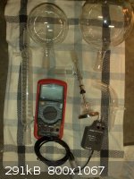
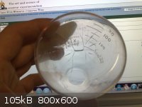
Finally Mossydie: shown is a beaker from a recent experiment. While drying a nitrate in my lab microwave (don't use the food microwave for chemistry,
random poisoning < Good times) the water boiled off as I watched and then the reaction continued the microwave happily melted my sodium nitrate
sample right to it's decomposing temperature. I ran and grabbed my respirator so as to watch this more carefully as the nitrogen oxides smell like
nothing else and you don't want them IN you. Indeed no water was left and it was an anhydrous sample. More amazing the beaker didn't crack or shatter
upon cooling from the stresses in the glass.
Curious I fired up the hotplate and took a sample of the same nitrate to molten. The beaker is the one shown in the picture. The microwave acted as a
furnace containing heat and heated the sample not the glass meaning there were far less stresses placed on the glass beaker. I have yet to really play
with this as it happened a couple days ago. I very much wish to attempt a reduction of nitrate to nitrite via a microwave, of all things.
Peach is right about organic chem temps. The most badass glass mercury thermometer I have goes to 320C (I only have a couple left, try getting bubbles
out of mercury when you have to take the glass to 350C to max it out and clear the bubbles). I bought them then ironically figured out to use a broken
thistle tube with the end melted shut and a type K thermocouple inside the tube with a drop of mineral oil to make better contact with the tube
itself. The whole point of distilling things like nitric acid under vacuum is to lower the boiling point beneath that of its decomposing temperature
(and save glassware). Essential oils with very high thermal mass will almost certainly be destroyed taking them to there (natural) boiling point to
distill them.
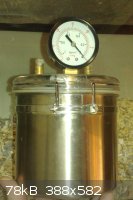 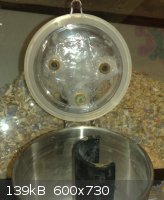 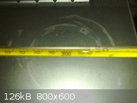 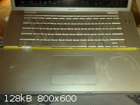 
[Edited on 7-2-2011 by Regolith]
|
|
|
peach
Bon Vivant
    
Posts: 1428
Registered: 14-11-2008
Member Is Offline
Mood: No Mood
|
|
For those in doubt, please have a read of the following post for why fridge compressors are a good idea
|
|
|
entropy51
Gone, but not forgotten
    
Posts: 1612
Registered: 30-5-2009
Member Is Offline
Mood: Fissile
|
|
What's all the yelling about? Amateurs have been cognizant of, and extensively using, fridge compressors as vacuum pumps since even I was a wee lad. Does "re-inventing the wheel" ring any bells? Sheesh.
There's an old thread on this topic from 2003. Old news.
The thread you are so proud of gives your measurements of ultimate pressure reached by the different pumps. As this sorely needed tutorial makes crystal clear, ultimate pressure is no predictor of pump performance in actual use. For that you need the pumping speed curve.
This is particularly true in a system with generation of vapor, such as a distillation or rotovap. Read the tutorial and you will have a much better
understanding of these vacuum fundamentals. If you had measured pumping speed and compared that all important measure of performance, I might have
been impressed. Ultimate pressure, not so much.
[Edited on 8-2-2011 by entropy51]
[Edited on 8-2-2011 by entropy51]
|
|
|
| Pages:
1
..
3
4
5
6
7
8 |
|