| Pages:
1
..
10
11
12
13
14
..
18 |
Magpie
lab constructor
    
Posts: 5939
Registered: 1-11-2003
Location: USA
Member Is Offline
Mood: Chemistry: the subtle science.
|
|
How much of the -ve electrode is actually exposed to the molten NaCl? That is, not encased in glass. I presume that is the only part of the
electrode that is generating Na.
Could this active part of the -ve electrode be the terminus of a J-shape. Then let the Na crawl up the wire and float to the larger glass tube for
capture and removal.
Then possibly you could make the capture tube of metal as it would not be electrically connected to the -ve electrode via Na bridging.
But these are geometry issues about which it is very hard to give any meaningful help and about which you are surely in the best position to solve.
The single most important condition for a successful synthesis is good mixing - Nicodem
|
|
|
209
Harmless

Posts: 20
Registered: 23-1-2007
Member Is Offline
Mood: No Mood
|
|
I am intrested in making a little sodium metal myself. Being that I don't have a power sourse of 5V @ 50 amps (maybe the arc welder?) I dont really
have a power sourse that is good enough to create the juice required. I do have a 12 volt transformer out of the wall that may work. Through personal
experience I have found that the totse forums really arn't that accurate  . So I don't know if the 12 volt transformer will work. Will it? . So I don't know if the 12 volt transformer will work. Will it?
|
|
|
b_d_Dom
Harmless

Posts: 32
Registered: 27-10-2006
Location: Canada
Member Is Offline
Mood: No Mood
|
|
| Quote: | Originally posted by 209
I am intrested in making a little sodium metal myself. Being that I don't have a power sourse of 5V @ 50 amps (maybe the arc welder?) I dont really
have a power sourse that is good enough to create the juice required. I do have a 12 volt transformer out of the wall that may work. Through personal
experience I have found that the totse forums really arn't that accurate  . So I don't know if the 12 volt transformer will work. Will it? . So I don't know if the 12 volt transformer will work. Will it?
|
If it is just a basic transformer then no. Unless it has a built in rectifier it is outputing AC which is no good for electrolysis.
You can build a rectifier for it if you have some diodes lying around, or just find yourself a DC power source.
If you have any questions on this subject just send me a U2U and I should be able to help.
|
|
|
Jdurg
Hazard to Others
  
Posts: 220
Registered: 10-6-2006
Location: Connecticut, USA
Member Is Offline
Mood: No Mood
|
|
It seems a bit odd that the Na is "attacking" the glass because there are many chemical suppliers who sell sodium metal in sealed glass ampoules.
This metal is obviously liquid when it is poured in there and the glass is perfectly fine. The only alkali metal I know of that attacks glass when
molten is lithium. Sodium, Potassium, Rubidium and Cesium all seem to be fine in the presence of glass. I wonder if there are impurities in the
glass, however, that might be reacting with sodium as there are more varities of glass in this world than there are people.
\"A real fart is beefy, has a density greater than or equal to the air surrounding it, consists of the unmistakable scent of broccoli, and usually
requires wiping afterwards.\"
http://maddox.xmission.com. |
|
|
tumadre
Hazard to Others
  
Posts: 172
Registered: 10-5-2005
Member Is Offline
Mood: No Mood
|
|
AFIK The issue is the sodium dissolves in the glass at that temperature.
anyone know if it it reacts at all?
I don't believe there is a reaction with the soda-lime glass, but whatever the case that is far too messy.
try a ceramic tube say 15 cm long bonded to a glass tube, the glass tube makes a 90 degree bend and goes into a negative pressure inert gas
atmosphere, and 'suck' the sodium out of the cell.
Put a copper cooling tube down the glass tube, so it cools the sodium to about 300-200C, so it don't melt the glass.
The 3-5 mm internal diameter ceramic tube will drop the temp from 550-600C to the 300/200C.
Regulate the vacuum to whatever is needed to keep the salt/sodium level to about 5 cm up the ceramic tube.
The sodium is the negative electrode
[Edited on 14-6-2007 by tumadre]
|
|
|
len1
National Hazard
   
Posts: 595
Registered: 1-3-2007
Member Is Offline
Mood: NZ 1 (goal) - Italy 1 (dive)
|
|
| Quote: | Originally posted by Jdurg
It seems a bit odd that the Na is "attacking" the glass because there are many chemical suppliers who sell sodium metal in sealed glass ampoules.
This metal is obviously liquid when it is poured in there and the glass is perfectly fine. The only alkali metal I know of that attacks glass when
molten is lithium. Sodium, Potassium, Rubidium and Cesium all seem to be fine in the presence of glass. I wonder if there are impurities in the
glass, however, that might be reacting with sodium as there are more varities of glass in this world than there are people. |
I also have some shinning Na in a clear glass ampule. I sucked it up from some of the globules formed when NaOH
was electrolised, i.e. at 300 degrees.
The sodium we have here is not at 300 degrees though, its at 600. There is clearly a black coating, you can see it in the
photo, on the pyrex tube. The coating only exists at those points were the Na touched it, not at others.
|
|
|
not_important
International Hazard
    
Posts: 3873
Registered: 21-7-2006
Member Is Offline
Mood: No Mood
|
|
When the glass is hot enough some sodium can diffuse into it. Once there it can exist as a metal, or reduce some of the ions in the glass. Depending
on what type of glass is being used I ould not be surprised to see a little reduction of Si, to the element or Si(II), or boron; iron and manganese
in ordinary soft glass would also undergo reduction down the the metals.
Note that glass starts becoming conductive when hot enough, although not really conductive. This has been used to prepare small amounts of very pure
sodium for absorption/emission studies, a electric light bulb was used as the electrode, the sodium formed on the inner surface and fresh sodium ions
diffused in from the moltan batch it was immersed in. The glass gets quite dark, and the inner surface becomes coated with a sodium mirror. The rate
of production is too slow for making useful amounts of sodium, but the related method using beta alumina mentioned earlier is fast enough.
|
|
|
len1
National Hazard
   
Posts: 595
Registered: 1-3-2007
Member Is Offline
Mood: NZ 1 (goal) - Italy 1 (dive)
|
|
I can also add that the molten sodium in the NaCl/CaCl2 mix has very high attraction towards any glass or ceramic surface. It wets it as a thin
layer, and then reacts. This is evidenced by a dark black patch at the bottom of the ceramic vessel in the picture at the point where the -ve
electrode touched it. Even though quite a bit of density differential exits between the melt and the sodium (2:1) forcing the Na to float, it was
energetically more favourable for it to wet the bottom completely, and react with it, as it formed, then float to the top. It clearly was also able
to crawl along the already reacted patch.
|
|
|
garage chemist
chemical wizard
    
Posts: 1803
Registered: 16-8-2004
Location: Germany
Member Is Offline
Mood: No Mood
|
|
There is a documentation on how to build a DIY castner cell on versuchschemie:
http://www.versuchschemie.de/topic,9576,0,-Na+aus+NaOH+elekt...
A fine stainless steel wire mesh is used as a diaphragm with good success. This really seems to be necessary, as industry uses it as well.
The cell is heated electrically- the wire wound on the glass fiber cloth is the heating which is wired in series to the cell after the NaOH has been
molten. It stays at the operating temperature when 7A flow through cell and heating. Every hour the sodium is scooped off with the special spoon. The
large white blob in the second to last picture is the sodium.
[Edited on 2-8-2007 by garage chemist]
|
|
|
len1
National Hazard
   
Posts: 595
Registered: 1-3-2007
Member Is Offline
Mood: NZ 1 (goal) - Italy 1 (dive)
|
|
The previous post describing a home-made Castner cell on a German forum was the perfect precursor to what I wanted to achieve, which is a good quality
permanent apparatus to produce Na on-tap. I believe I now have this.
Although the pictures in the previous post were an inspiration, the text wasnt, Ive never learnt any german, and after reading the Babelfish
translation I was so confused I simply tried reading the original text using the similarity of some German words to the english to make sense.
In any case the key problems with the original experiment (which is perfectly fine for a pilot-run) that I identified were:
1) fairly flimsy nature of apparatus - the Na collector just sits in the melt - if you heat it too high, it will move.
2) The container walls are used as an anode, which is not how Castner operates, leading to wall erosion, as well as making it impossible to use
nickel in the anode, by far the most sturdy material when it comes to dissolution under potential in molten NaOH
3) The bottom of the vessel was ramed clay, exposed directly to NaOH at near melting temperature - although the original experiment tried to maintain
a temperature differential so the bottom NaOH is solid, in practice its hard to do, and in any case at elevated temperatures the clay will rapidly
dissolve (my experinments show molten NaOH attacks clay at the order of 1mm per 10 mins). The dissolution of the clay leads to substantial
contamination of the bath, shortens its life, as well as leading to perforation at the bottom with time.
4) The low amperage of the cell resulting from (3) means you have to wait all day to get even a few grams of Na.
The several areas of the original which were used unchanged was
1) The cathode was made of wound Cu tube of short cross section rather than solid. That is a great idea comapred to a solid Cu cathode- meaning much
reduced heat loss through Cu notorious heat conductivity, a much more unifrom temperature of the bath, which is essential for any reasonable yield in
this case.
2) The Na collector was a slotted pipe into which a thin wire gauze (sold in Woolworths for toasters) was inserted, and held up extremely well.
3) The cell was heated from the outside with insulation provided by fibreglass.
The present construction (of which more will follow) has the following features:
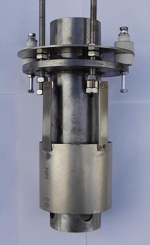
1) A cylinder anode of 1mm Ni sheet of 6cm diameter by 5 cm long attached by adjustable SS bolts to a top circular plate separated from the collector
and casing by ceramic insulators scavanged from a radiation heater
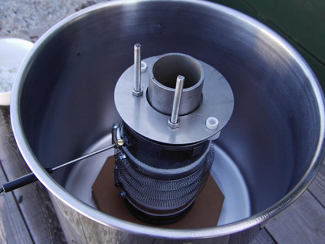
2) A NiCr heating element scavanged from the same heater wound around fibreglass matting and providing 300W of power. The fibregalss was held in a
wound state around the outside of the cell ny two stainless steel hose clips. Each of the hoseclips also acted as a terminal for the heating element.
This provides a sturdy constrcution.
3) An outer radiative-heat container of SS (an indian cofee jar from woolworths) of 15cm diameter and 15 cm long encased the cell with wound NiCr.
4) Holes drilled in the radiative container with terminal posts attached to bolts drilled in the hose clamps allowed the passage of heating current
at 240V. Note its independent of electrolysis current, and is only needed at startup. A hole also passed a thermocouple probe held by a screw clamp
to the cell body. It was found that 365C was the ideal temperature for bath melting - while 320C was ideal for electrolysis.
5) The cell measured 8cm diameter x 15.5cm and held 1 kg of caustic, which although full when cold, filled it half-way when molten - this reduced
heat variation in the bath due to collector protrusion.
6) A lided SS pot 25cm diameter 22cm long filled with glass wool formed the outer insulation. The pot was bolted to a long stand admitting a
receptacle which was passed cathode.
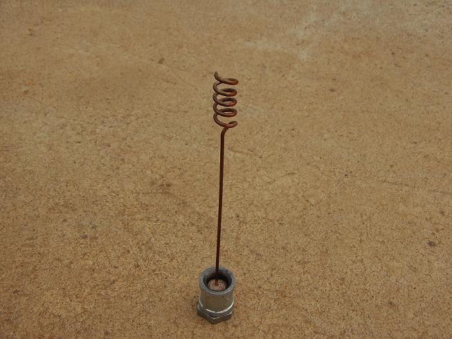
7) The cathode was 5cm long 15mm diameter wound copper tubing. Fixed at the bottom (cool end) to a threaded nut and sealed with exhaust cement.
8) Temperatures measured were 100C for bottom of SS pot, 66C for top, 44C for lower end of cathode stem, 33C for cathode, 150C for anode terminals,
270C for top of Na collector, 320C for bath inside collector.
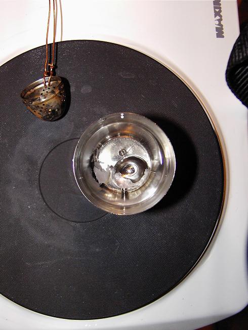
9) The Na was collected by a perforated ladel. This let the bath pass thru as stated - has liquid Na got a high surface tension! A lot was wasted
still clinging to the ladel - and you had to shake it really hard to get even half of it to drop into the parafin at 140C
10) The bath current was 47 - 50A. Experiment time was about an hour to produce the sodium shown.
[Edited on 10-9-2007 by len1]
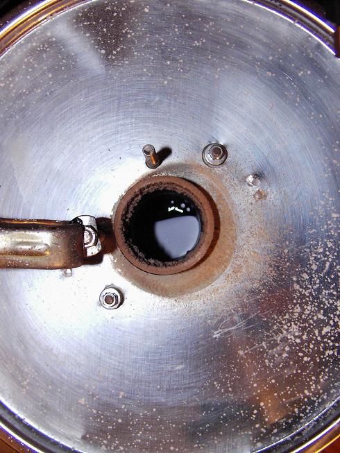
|
|
|
len1
National Hazard
   
Posts: 595
Registered: 1-3-2007
Member Is Offline
Mood: NZ 1 (goal) - Italy 1 (dive)
|
|
Here are some more pics. I havent worked out how to post more than 1 at a time
[Edited on 10-9-2007 by len1]
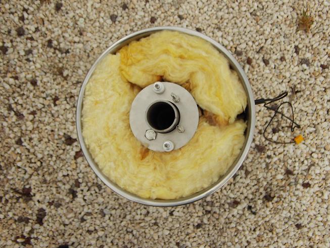
|
|
|
len1
National Hazard
   
Posts: 595
Registered: 1-3-2007
Member Is Offline
Mood: NZ 1 (goal) - Italy 1 (dive)
|
|
The power supply
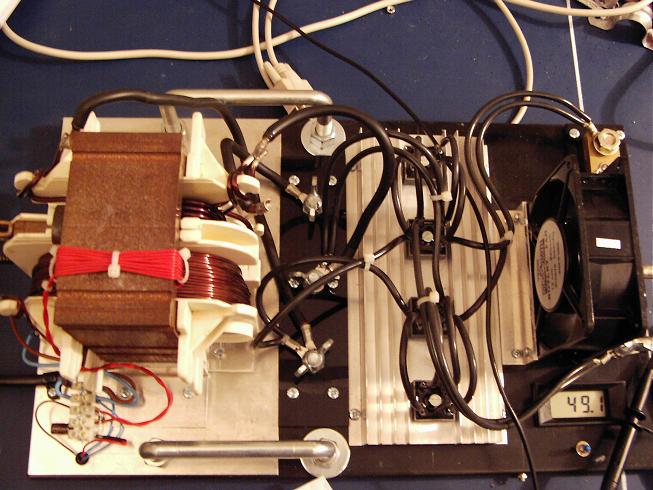
|
|
|
len1
National Hazard
   
Posts: 595
Registered: 1-3-2007
Member Is Offline
Mood: NZ 1 (goal) - Italy 1 (dive)
|
|
The sodium
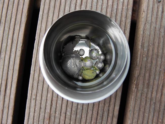
|
|
|
len1
National Hazard
   
Posts: 595
Registered: 1-3-2007
Member Is Offline
Mood: NZ 1 (goal) - Italy 1 (dive)
|
|
The ladel
|
|
|
len1
National Hazard
   
Posts: 595
Registered: 1-3-2007
Member Is Offline
Mood: NZ 1 (goal) - Italy 1 (dive)
|
|
The Cathode
|
|
|
12AX7
Post Harlot
    
Posts: 4803
Registered: 8-3-2005
Location: oscillating
Member Is Offline
Mood: informative
|
|
Very nice! :thumbsup:
|
|
|
len1
National Hazard
   
Posts: 595
Registered: 1-3-2007
Member Is Offline
Mood: NZ 1 (goal) - Italy 1 (dive)
|
|
Thanks Tim
Following are more pictures of the Na cell internals. This is
the annular Ni anode attached to the Na collector
|
|
|
len1
National Hazard
   
Posts: 595
Registered: 1-3-2007
Member Is Offline
Mood: NZ 1 (goal) - Italy 1 (dive)
|
|
This shows the heating coils wound around the outside of the cell, they are needed only to initially melt the NaOH. The 50A current @4.6V is then
just perfect for maintaining cell temperature
[Edited on 12-9-2007 by len1]
|
|
|
12AX7
Post Harlot
    
Posts: 4803
Registered: 8-3-2005
Location: oscillating
Member Is Offline
Mood: informative
|
|
Ni....cathode?
|
|
|
len1
National Hazard
   
Posts: 595
Registered: 1-3-2007
Member Is Offline
Mood: NZ 1 (goal) - Italy 1 (dive)
|
|
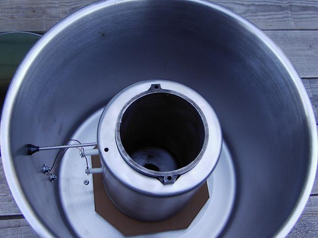
This shows the radiation shield in place, with protrusions for the thermocouple and the heating coil binding posts.
|
|
|
len1
National Hazard
   
Posts: 595
Registered: 1-3-2007
Member Is Offline
Mood: NZ 1 (goal) - Italy 1 (dive)
|
|
No, Ni anode is right. The cathode is of copper. Thats the standard arrangement for a Castner. The anode is were the greatest potential for
corrosion exists and so needs to be made of a metal least sensitive to corrosion in NaOH.
Unless you are thinking of a voltaic cell where the carthode and anode are the other way around, but in an electrolysis cell I believe thre labeling
is right. The terminal to which the +ve voltage is applied is the anode
|
|
|
Magpie
lab constructor
    
Posts: 5939
Registered: 1-11-2003
Location: USA
Member Is Offline
Mood: Chemistry: the subtle science.
|
|
Very nice len. Your apparatus looks well engineered providing ruggedness and reliability in a compact assembly. Yet it probably still minimizes cost
and maximizes use of OTC parts. You did do some welding though it looks like?
I'm glad you posted some more pictures. I was having a heck of a time trying to figure out how your cell was assembled! Please post some more.
Where does the "toaster gauze" fit in? We haven't seen that yet have we? BTW what is "toaster gauze?"
Did you assemble the power supply yourself? If so, please provide some details.
(BTW, your reference to Woolworth's is interesting. When I was young we had "five and dime" Woolworth stores. But they no longer exist in the US. I
see that Woolworth stores still survive in other parts of the world, however. And in Australia and New Zealand the stores are unrelated to the
orginal US stores by that name. )
[Edited on by Magpie]
The single most important condition for a successful synthesis is good mixing - Nicodem
|
|
|
len1
National Hazard
   
Posts: 595
Registered: 1-3-2007
Member Is Offline
Mood: NZ 1 (goal) - Italy 1 (dive)
|
|
| Quote: | Originally posted by Magpie
Very nice len. Your apparatus looks well engineered providing ruggedness and reliability in a compact assembly. Yet it probably still minimizes cost
and maximizes use of OTC parts. You did do some welding though it looks like?
I'm glad you posted some more pictures. I was having a heck of a time trying to figure out how your cell was assembled! Please post some more.
Where does the "toaster gauze" fit in? We haven't seen that yet have we? BTW what is "toaster gauze?"
Did you assemble the power supply yourself? If so, please provide some details.
(BTW, your reference to Woolworth's is interesting. When I was young we had "five and dime" Woolworth stores. But they no longer exist in the US. I
see that Woolworth stores still survive in other parts of the world, however. And in Australia and New Zealand the stores are unrelated to the
orginal US stores by that name. )
[Edited on by Magpie] |
Hi Magpie, nice to hear from you again. Thanks for the words of encouragement. I had a project for a DIY Castner cell in mind for a long time (I
dont think anyone has published a design before) but I couldnt get to doing the pilot experiments to see what worked. There were so many options.
Then I saw the link garage chemist posted and thought this is the pilot run I was looking for. I still had to solve a few problems (such as how to
isolate the colelctor from the anode) but the pilot showed this approach works on a semi-scale in principle.
Im very interested to see others repeat this project and introduce their own alterations. After all we have 12 pages in this thread so lets have a
great outcome.
I have lots more pics but wasnt sure if positing so many would be what people on this forum wanted. Im willing to post more + answer questions, if
people want. I dont know how to post several pics in one post.
I did do some welding, but you get change from $100 for welding machines were I live. The bits that had to be welded were the cathode stem to cell
base, cell base to cell walls, and cell top to Na collector. The later can easily be avoided though. You could avoid the former by using a cast iron
pot rather than a pipe and using a threaded base stem and nut to attach to the bottom of the later. I just couldnt find the right sized pot.
Toaster gauze is stainless steel fine mesh sold here to go in some sort of toaster I believe. To be honest I didnt really care much for the toaster
so dont know how it goes in there. You can also get SS gauze from camping stores here.
I didnt know 'woolies' as we call them here is from the US. Yes its alive and well in Australia/NZ, competing with Kmart (your Walmart I believe)
Len
|
|
|
DerAlte
National Hazard
   
Posts: 779
Registered: 14-5-2007
Location: Erehwon
Member Is Offline
Mood: Disgusted
|
|
Superb work, Len 1. A thread stopper!
Der Alte.
|
|
|
12AX7
Post Harlot
    
Posts: 4803
Registered: 8-3-2005
Location: oscillating
Member Is Offline
Mood: informative
|
|
Huh, then I'm confused about where the sodium comes from.
So the nickel anode bubbles off -- you said Castner, so this is NaOH? -- O2 and H2O, while the cathode is placed in the center of the shield and
periodically harvested?
Tim
|
|
|
| Pages:
1
..
10
11
12
13
14
..
18 |