| Pages:
1
2 |
Rainwater
National Hazard
   
Posts: 959
Registered: 22-12-2021
Member Is Offline
Mood: Break'n glass & kick'n a's
|
|
Last major update until parts come in.
A setup a structer to write custom driver code.
I included a driver for the G540 op is using..
pinout is in the _use_g540.h file.
demo sketch is setup to drive your servo at 1 rotation per second for 50 seconds.
let me know if it sets your controller on fire
"You can't do that" - challenge accepted
|
|
|
Texium
|
Thread Moved
19-11-2023 at 09:47 |
mc68k
Harmless

Posts: 24
Registered: 26-10-2023
Location: Durham, NC, USA
Member Is Offline
|
|
Rainwater - Nice progress! Can't wait to see your hardware vision realized.
I've ordered some parts off your BoM, so we will have some equivalent hardware to test with.
What are the IR sensors for? I don't see that mentioned anywhere. Looks like they are send/receive boards, so maybe wireless comms?
I'll look through the new code, sounds like you added support for steppers too.
[EDIT: Did the link change? I don't see the files you reference in the previous reply (_use_g540.h).]
Progress:
- Fixed the overheating valve stepper
- Successfully ran the valve selection test, shifting to each position in turn and pumping water through it
- Started a manual synthesis of the target molecule to test the experimental
Experimental:
Glycine + Urea -> Hydantoin:
----------------------------
1.00 g (13.32 mmol) Glycine
0.85 g (14.00 mmol) Urea
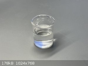
Glycine and Urea were placed in a 10 mL beaker.
Approximately 6 mL water added and stirred until everything dissolved.
Heated in microwave (on low) for 1 minute, then stir.
Heating/stirring repeated for 10 minutes, never allowing the beaker to boil.
Beaker left overnight to cool and complete reaction.
Acidify to pH 2 by drop-wise addition of aqueous HCl 37%.
Acidified mixture poured into evaporation dish and warmed on hotplate.
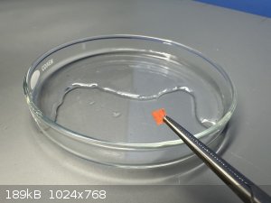
After crystals formed spontaneously the dish was left to evaporate at room temperature for 24 hours.
Crystals (still wet) were scraped together and 2 mL fresh water added to the dish, stirring the wet crystals into the fresh water to wash them.
Crystals were scraped to one side of the dish and the liquid left to evaporate again.
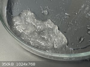
Still waiting for the crystals to dry so I can weigh them.
[Edited on 20-11-2023 by mc68k]
move.w %0x2700,sr
movem.l d0-d7/a0-a6,-(a7)
lea science,a0
jsr madness
|
|
|
Rainwater
National Hazard
   
Posts: 959
Registered: 22-12-2021
Member Is Offline
Mood: Break'n glass & kick'n a's
|
|
Sorry,i broke the code yesterday and
im horrible about keeping backup files.
I post gethub link as soon as its fixed.
"You can't do that" - challenge accepted
|
|
|
Rainwater
National Hazard
   
Posts: 959
Registered: 22-12-2021
Member Is Offline
Mood: Break'n glass & kick'n a's
|
|
Permanent home - https://github.com/Adivinedude/PCM_Modbus
1 uno with the hardware I linked can run
4 dc motors (2amp 7-32v)
4 5v logic servos
2 stepper motors, in full steps, 2 amps, 7-32 volt, at 1.5k steps per second
4 pulse step drivers.
not all at once, but many workable combinations.
this is just version 0.1 there is a lot of room to grow.
added a pulse step mode for your G540 per their datasheet
clocked her at 5.6k steps per second.
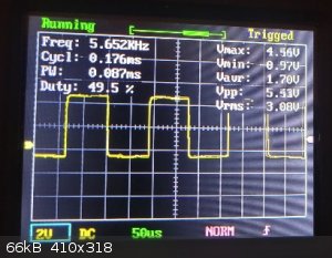
That is a really nice driver by the way. out of my price range.
That will most likely rip the gears our of your pump if you drive it that fast.
I will add a some bits to control acceleration but will be after the holidays.
as for your overheating issue.
be sure to use the proper current setting resistor. that driver works like a current
source, at slow speeds it uses less voltage, but as speeds increases, the
impedance of the motor coils goes up, requiring more voltage to drive the load at
full current/power.
Without the proper resistor, it will overvolte the motor at lower rpm and holding states
Using my little setup, torque will be lower at high speed because an h-bridge is not
a good way to drive a stepper. it works but there are better options.
None which can operate this wide variety of motors for this price point.
Was reading though github,
they did a professional job.
https://github.com/croningp/ChemputerSoftware/tree/master
Thinking of using this little toy to mod a broken hotplate stirrer to digital controls.
Knobs keep melting off, i've put this one through a lot.
"You can't do that" - challenge accepted
|
|
|
mc68k
Harmless

Posts: 24
Registered: 26-10-2023
Location: Durham, NC, USA
Member Is Offline
|
|
Quote: Originally posted by Rainwater  | 4 dc motors (2amp 7-32v)
4 5v logic servos
2 stepper motors, in full steps, 2 amps, 7-32 volt, at 1.5k steps per second
4 pulse step drivers |
Perfect! I'll read the code over the holiday, looks like a lot of changes. Also, my parts have shipped, so I can replicate the setup next week-ish.
Yes, they've been at it for many years and have published a lot of good hardware and software designs. I've only perused their code briefly, still
have a few bits and pieces to work out before I can try integrating with their platform.
Quote: Originally posted by Rainwater  | Thinking of using this little toy to mod a broken hotplate stirrer to digital controls.
Knobs keep melting off, i've put this one through a lot. |
I recently dismantled my manual heat plate/stirrer to see what it would take to control it using the Arduino. Not quite done with the
reverse-engineering for that though, but it looks like we're both going in the same direction.
Progress:
- Splitting off the experimental thread so it won't dilute the hardware design work being done here (link).
- Got the basic 'liquid handling backbone' working, equivalent to the chemputer's use of syringe pumps:
Set valve to point to beaker 1
Pump from beaker 1 to transfer beaker
Set valve to point to beaker 2
Pump from transfer beaker to beaker 2
Sensor Testing:
Totally pulling my hair out on these photo-interrupters. Does anyone see where I may have gone wrong?
I've attached a reverse-engineered wiring for the sensor board, a breadboard test circuit, and the wiring diagrams from the documentation of the
photo-interrupters.
If I understand the circuit correctly, it should work like this:
- When powered with 5V, the photo-interrupter's LED (labeled A,K) will illuminate continuously.
- This will allow current to flow across the photo-interrupter's detector (labeled C,E).
- Since the collector is tied to 5V, the emitter will pass 5V until the LED is blocked.
- The output pin will read HIGH.
- Once the LED is blocked, the collector stops passing current, leaving the emitter to float.
- The floating emitter is tied to ground by a high-resistance path.
- Thus the output will read LOW.
I've tested various pull-down resistors, specifically 1K, 20K, and 1M, which I've seen mentioned in some hardware threads for similar circuits.
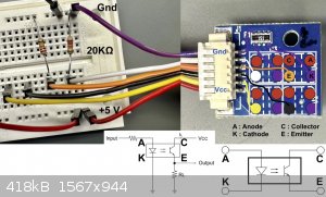
[Edited on 22-11-2023 by mc68k]
move.w %0x2700,sr
movem.l d0-d7/a0-a6,-(a7)
lea science,a0
jsr madness
|
|
|
Rainwater
National Hazard
   
Posts: 959
Registered: 22-12-2021
Member Is Offline
Mood: Break'n glass & kick'n a's
|
|
On your drawing you have
"Input" > resistor > 'A'. Assuming "input" is Vcc to power the led, then your wiring is backwards
You have "purple wire" Gnd > resistor >anode
It doesn't matters but is convention to place resistors before the anode on leds.
Got a good meter?
1. Ohm out each channel of the resistor array. (black chip labled 151) make sure they are all equal +/- 10%
2. Switch to diode test and ring out the leds, verify orientation (cathode and anode), and record the voltage drop.
These 2 test and measurements will tell you everything you need to know to about
this circuit
For example, if the K/A voltage drop is ~2.0V and the resistor is 150ohms,
assuming a current of 10-20ma(standard current for this type of device) we can say
Vcc = resistance * current + diode voltage drop
Vcc = 150ohms * 20×10^-3 + 2v = 5v
Or 150ohms * 10ma + 2v = 3.5V.
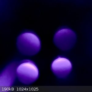
A cool way to test an IR led is to power it, turn off all lights, and view it through a cell
phone camera. It will show up as a redish purple. Great for tv remotes.
Edit: 20k pull down resisters are kinda big and will limit the output reaction speed.
The emmitor collector capacitance will form large RC time constance.
Also, shield the device from all light sources when testing. Just in case ambient
light is an issue
[Edited on 23-11-2023 by Rainwater]
[Edited on 23-11-2023 by Rainwater]
"You can't do that" - challenge accepted
|
|
|
mc68k
Harmless

Posts: 24
Registered: 26-10-2023
Location: Durham, NC, USA
Member Is Offline
|
|
Ok.. you shamed me into getting a real ohmmeter. Had an old one that died awhile back and I've been limping along with a household voltmeter since.
Checked the resistor: 149, 149, 150, 148
Checked the diodes: You're correct they are reversed - the data sheets I found are not compatible with the parts on the board.
Verified this using my cellphone camera by powering the circuit and reversing the connections (purple = +5v, red = Gnd).
Finally wired it all back up with the Arduino and tested the inputs with a 10K resistor.
It works!
PCM_Modbus:
I got some time to read through the code and compile it.
When compiling using the Arduino IDE, there is a multi-definition conflict for PCINT0_vect, which is being used by the Serial library, and also for
the feedback interrupts. I poked around and could get the feedback system to use the Arduino attach/detach interrupt API. Not sure if this is valid
for your use case, but it got me through the compilation.
Checking the wiring diagram, the only thing I noticed was the MOSI pin seems to be used twice (ICSP MOSI -> MAX485 pins 2,3) and (D11 PWM/MOSI
-> L298 U3 pin 11). I think these are the same pin?
Perhaps this is already documented, but the ModBus commands to setup various kinds of motors, and start/stop them, etc. I see one example in the
debug code, but I'm not sure what combinations are valid. Ie: does a DC motor need the feedback turned on or off?
move.w %0x2700,sr
movem.l d0-d7/a0-a6,-(a7)
lea science,a0
jsr madness
|
|
|
Rainwater
National Hazard
   
Posts: 959
Registered: 22-12-2021
Member Is Offline
Mood: Break'n glass & kick'n a's
|
|
Im building it with arduino ide 2.2.1. On windows.
It will build stright from the zip file now.
D11 on the left going to the MAX485. Is labled wrong.
That is a drawing error.
For some reason they dont show A4 on the drawing and i
didnt catch that.
If you read "pins.h" lines #41-#66, it list each and every pin clearly
I will update the usage.txt with more details about how motor types can be
configured in the next few days.
In short, dc motors, servos, pulse step, each use 1 pump channel. And can be
applied in any combination.
While stepper motors use 2 pump channels and can only be configured on pump 1 and pump 3
If pump1 is configured as a stepper, you lose pump2,
if pump3 is configured as a stepper, you lose pump4
Feedback inputs are completely optional.
With feedback set to 0, Dc motors use milliseconds, pulse step and steppers use
steps. And servos currently dont do nothing with them because I haven't
implemented that as a pump yet.
If you have a flow meter, it will ether produce a pulse per unit of flow or an analog
voltage. This unit only has 1 unused pin, and its an analog, so if its needed its there.
1 analog voltage as feedback could be used, but its not currently in the program.
adjustable voltage to frequency converters are cheap, and can take that type of output and convert it into pulses.
Flow meters are so expensive, i made this bit optional because most people will not
have one.
Currently working on a console program to run all this. Will likly wire a esp32 as a
wifi modbuxTCP to modbusRTU gateway so i can watch tv and monitor reactions on
my phone.
[Edited on 25-11-2023 by Rainwater]
[Edited on 25-11-2023 by Rainwater]
"You can't do that" - challenge accepted
|
|
|
mc68k
Harmless

Posts: 24
Registered: 26-10-2023
Location: Durham, NC, USA
Member Is Offline
|
|
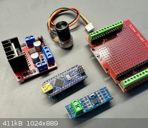
Stuff arrived! I'll get on the breadboard construction and test out the new code.
Rather than one controller controlling 4 pumps of various types, I'm thinking of packaging each Arduino with parts such that it can control:
- Valve (stepper + inputs)
- Stirring (DC motor)
- Hotplate (PWM)
- Thermometer
- Pump (stepper)
This would simplify my setup because I can design one box containing all the components needed (resistors, knobs, plugs) to run any piece of
equipment. Then deploying new equipment (valve, hotplate, etc) is just plugging it in to the appropriate free port on one of the control boxes and
adjusting the config files to describe what equipment is connected.
move.w %0x2700,sr
movem.l d0-d7/a0-a6,-(a7)
lea science,a0
jsr madness
|
|
|
mc68k
Harmless

Posts: 24
Registered: 26-10-2023
Location: Durham, NC, USA
Member Is Offline
|
|
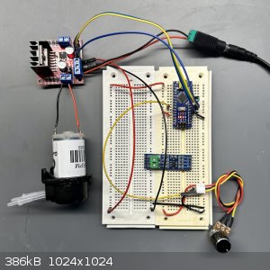
It lives!
Excellent work Rainwater, the latest code ran right out of the box. Had a bad motor driver (L298), did a bit of code debugging only to discover it's
a bad board, ugh!
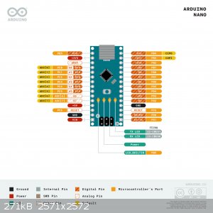
Haven't attached the ModBus board yet, the pins are labeled differently from your schematic.
Pins on board: DI, DE, RE, RO
I'm assuming the pins are RO->RX, DI->TX, and DE/RE tied together, but to which pin? Still using MOSI?
Also, do all ModBus devices tie their pin 'A's together and all the pin 'B's tied together (like a bus), or are they plugged in serially (like pin A
of device1 goes to pin B of device2, etc)?
Thanks, this will accelerate the project nicely!
move.w %0x2700,sr
movem.l d0-d7/a0-a6,-(a7)
lea science,a0
jsr madness
|
|
|
Rainwater
National Hazard
   
Posts: 959
Registered: 22-12-2021
Member Is Offline
Mood: Break'n glass & kick'n a's
|
|
https://github.com/Adivinedude/PCM_Modbus/blob/main/sketch_P...
| Code: | for the ATmega328p
RS485_TX 1 // PD1
RS485_RX 0 // PD0
RS485_DERE 18 // A4 PC4 |
| Quote: | Also, do all ModBus devices tie their pin 'A's together and all the pin 'B's tied
together |
yes
Be sure to use a common ground between your controller and devices. Earth ground
should work. Ensure ground resistance between all devices is less than 100 ohms.
This will prevent common mode offsets that will damage the MAX485 above
15v/-15v and eliminates a lot of transmission noise.
If earth ground is unacceptable, using a 3 wire communication cable to carry the
ground will fix this.
[Edited on 1-12-2023 by Rainwater]
"You can't do that" - challenge accepted
|
|
|
Rainwater
National Hazard
   
Posts: 959
Registered: 22-12-2021
Member Is Offline
Mood: Break'n glass & kick'n a's
|
|
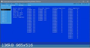
Its just a shell right now, gonna start adding communication functionality here soon.
I been working on the PCM_Modbus code by hand writing request, not fun.
I slapped this together while I recovered from the flu. should be working soon.
Currently taking request for features
ToDo List:
Translate modbus addresses into readable names
Spotlight Changed Values
Implement Command Passthrough
Pick better colors
"You can't do that" - challenge accepted
|
|
|
mc68k
Harmless

Posts: 24
Registered: 26-10-2023
Location: Durham, NC, USA
Member Is Offline
|
|
Chemputer Hardware:
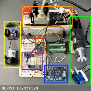
| Code: |
Red (center) : Arduino Nano microcontroller
Orange (top) : G540 stepper driver
Yellow (left): L298 DC motor driver board (top) + peristaltic pump (bottom)
Green (right): Liquid port selector valve (top) + peristaltic pump (bottom)
Blue (bottom): PWM to A/C dimmer board to control a hotplate
Purple (ctr) : MAC485 ModBus port for communication and rotary knob for address selection
|
Chemputer Progress:
- Rainwater's code controls all the pumps and ModBus communications.
- My valve control code is separate, not yet integrated with Rainwater's state machine.
- I added a simple serial command parser to turn on/off the various components.
- I replaced the POT with a rotary knob, which is more precise, and has a button for selection.
- The board on the bottom (blue) is new and hasn't been tested yet. It should allow the Arduino to control a hotplate using a single PWM pin! (https://www.amazon.com/dp/B06Y1DT1WP)
- I reserved the I2C pins for a few peripheral boards that should round out the package: LCD display, data logger, and balanced PT100 temperature
sensor board.
So this tangle of wires represents an almost-complete controller module! It's only missing the temperature sensor.
The expectation is that a chemputer would consist of several of these controllers, each controlling a reaction vessel (with hotplate, stirring,
temperature sensor) and add additional capacity to the liquid handling backbone (6 ports and a pump).
My target is 3 of these modules - that will enable control of the main reactor, filter module, and liquid/liquid separator. It also allows selection
among (6*3=18) ports. Although some ports are reserved, and some ports are used to connect the valves to each other.
The main valve has water, gas, vacuum, and waste connected to four of its ports. The last two ports connect to the other two valves. This means
there's really only 12 ports available.
Destination modules:
- Reactor
- Filter
- Separator
The remaining 9 ports are available for reagents.
Rainwater,
I like the colors! Very cool and soothing.
The console app looks great, that will be very useful for testing and debugging. The changed-value highlighting would be especially amazing.
I agree that sending ModBus commands "by hand" is aggravating. I resorted to writing individual test functions and invoking them through the Arduino
serial port. For example, typing "+0" turns on pump 0, while "-0" turns it off, and "S0100" where 'S' means 'set speed', the first 0 is the pump
number, and the last 3 digits is the desired speed.
move.w %0x2700,sr
movem.l d0-d7/a0-a6,-(a7)
lea science,a0
jsr madness
|
|
|
Rainwater
National Hazard
   
Posts: 959
Registered: 22-12-2021
Member Is Offline
Mood: Break'n glass & kick'n a's
|
|
Ive got the console app about 95% complete.
Its turned into a small scall project all its own.
Almost 3k lines of code.
But i have discovered limitations in the PCM which i have gotten on my nerves.
When using a dc motor, setting calibration to 1000
the maxium time the motor can run is 65 seconds.
If you attempt to run it longer, the controller sets the error flag because the highest
it can count is 216 or 65536.
Im going to make changes to the addresses to that the PCM can report back a 32bit value.
This will extended the run time with 1ms resolution up to 49 days.
Second nerve twitching thing I noticed, after keeping my head in the console app,
the Arduino firmware is harder to read and follow.
Gonna rewrite all that to make it easier.
Im not sure how well the arduino compiler will optimize class resources.
Given its an incomplete instruction set. We will see. Normally with mcu's
The overhead of managing an object structure with vtables is not worth it.
Once thats done, speed control and a script interpreter are next on the list.
[Edited on 20-12-2023 by Rainwater]
"You can't do that" - challenge accepted
|
|
|
Rainwater
National Hazard
   
Posts: 959
Registered: 22-12-2021
Member Is Offline
Mood: Break'n glass & kick'n a's
|
|
Finally, that was a real pain in the ass. just under 32 hundred lines, but i'm pleased with it.
https://github.com/Adivinedude/Modbus_Client
Merry Christmas, let me know if you have trouble building it.
Quick Video
[Edited on 22-12-2023 by Rainwater]
"You can't do that" - challenge accepted
|
|
|
Rainwater
National Hazard
   
Posts: 959
Registered: 22-12-2021
Member Is Offline
Mood: Break'n glass & kick'n a's
|
|
Just posted a major revision to the PCM firmware. It is a lot easier to read now.
Adding drivers is much simpler to.
Let me know what you need it to do, and i'll get a driver wrote up.
"You can't do that" - challenge accepted
|
|
|
VincenzoTheGreat
Harmless

Posts: 6
Registered: 4-3-2019
Member Is Offline
|
|
what make/model is the valve selector? $35 on ebay sounds like a steal, I wouldn't mind grabbing one or two myself.
|
|
|
| Pages:
1
2 |
|