| Pages:
1
2 |
Cendre
Harmless

Posts: 23
Registered: 1-12-2023
Location: California/France
Member Is Offline
Mood: No Mood
|
|
Ika cmag hs7 fried circuit
I plugged in an American Ika cmag hs7 120V in a European socket 230V. I’m not sure how to repair it, if it is repairable at all. It is the analogic
version. If there is a fuse or anything to replace that would be really helpful.
|
|
|
bnull
Hazard to Others
Posts: 269
Registered: 15-1-2024
Location: Between the Atlantic and the Pacific Ocean
Member Is Offline
Mood: Sleepy (again)
|
|
There are two possibilities: the fuses have died and nothing else; or one of those multipin components that are quite hard to remove without damaging
something else has burned. Since you plugged the poor little fella in a 230 V outlet, I would start by checking the fuses*, replacing them
if necessary, and checking the two orange relays. When you have access to a proper 120 V outlet, see if the stirrer runs. If it still doesn't, I
recommend you buy a replacement (IKA sells spare parts) as you may have fried the and be more careful next time.
*: which is something that I forgot to mention and @Jenks wisefully suggested below. Thank you,
@Jenks.
Edit: I downloaded the spare parts manuals for both the US and European versions of your stirrer. This is an image of the PCB at the
end of the manuals, with the most probable culprits inside the rectangles.
The fuses may have blown. Test them with a multimeter. They may be OK since you mentioned somewhere else that the stirrer worked
for about 10 minutes. But a test won't hurt, right?
If the relays are rated to 12 V DC, they may be dead. But I suppose IKA uses a basic PCB for both US and European models, with some crucial
component changes here and there (transformer) and the rest more or less the same (30 V DC relays as in the image).
The rated voltage of the optocoupler may have been exceeded and it burned. Easy to replace, of course.
They are phototriacs rated to 6 V (https://www.datasheetcatalog.com/datasheets_pdf/M/O/C/3/MOC3...), if I did read the numbers right. If the input voltage exceeded that, they're
dead.
Finally, the microcontroller. If it is dead, order a replacement. Removing the old and soldering a new is more trouble than it is worth and you
will damage something else.
Could please post a picture of your PCB?
[Edited on 22-6-2024 by bnull]
Quod scripsi, scripsi.
B. N. Ull
P.S.: Did you know that we have a Library?
|
|
|
Jenks
Hazard to Others
Posts: 143
Registered: 1-12-2019
Member Is Offline
|
|
Or check the fuses with a multimeter first.
|
|
|
Twospoons
International Hazard
Posts: 1301
Registered: 26-7-2004
Location: Middle Earth
Member Is Offline
Mood: A trace of hope...
|
|
I'd be looking downstream of that transformer. High chance the rectifier(s) are dead, and possibly the filter capacitors too, since both would have
been hit with double the design voltage. Most likely is the capacitors were overvolted and shorted, which would then overcurrent the rectifier, also
likely to blow short, which would then take out the fuses. If you're really unlucky you would have briefly got low voltage AC on the regulator,
blowing that and which ever was the weakest piece of silicon connected to it.
Put it this way: fuses are never the problem - they're only there to prevent fires when something else breaks.
Helicopter: "helico" -> spiral, "pter" -> with wings
|
|
|
Cendre
Harmless
Posts: 23
Registered: 1-12-2023
Location: California/France
Member Is Offline
Mood: No Mood
|
|
Thank you that’s incredibly helpful. I don’t have it right now but as soon as I have access to it (Friday) I’ll send a pic. I also have a second
older unit which I believe received the same fate, I’ll send photos of both PCBs
|
|
|
Cendre
Harmless
Posts: 23
Registered: 1-12-2023
Location: California/France
Member Is Offline
Mood: No Mood
|
|
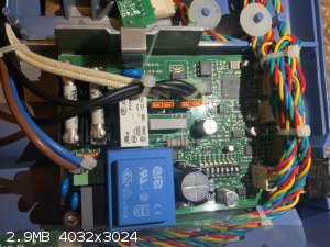
Here are photos of the PCBs of both units.
The fuses of both have continuity and when I short the upper phototriac on its left pins the motor starts to spin erratically, again for both units.
There is no visible damage on either PCB.
I am not sure how to test the various components as I am not familiar with electronics.
If anyone has any ideas from the information provided or has any thing they want me to test please tell me.
Thank you again to everyone who replied to the thread and helps me with this.
|
|
|
bnull
Hazard to Others
Posts: 269
Registered: 15-1-2024
Location: Between the Atlantic and the Pacific Ocean
Member Is Offline
Mood: Sleepy (again)
|
|
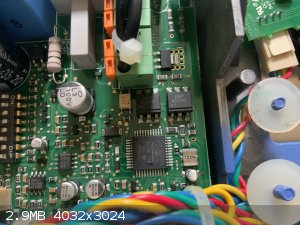
Could you please confirm if the phototriacs are MOC3083? The label is a little blurred.
You plugged them to a 120 V outlet this time, right?
Assuming you did and that you have and know how to operate a soldering iron, there are some things you can do. The left side pins (upper and lower,
middle pin isn't part of the circuit) of the chip are the triac pins (4 and 6 in the diagram shown on the datasheet). Since the motor spins when you
short them, the problem seems to be the LED part of the chip. The erratic spinning is most probably due to the fact that the motor is not continuously
powered. There is a feedback circuit somewhere that signals to the microcontroller when energy should be sent to the motor. The microcontroller sends
pulses to the LED side of the chip (pins 2 and 1, middle and bottom right on the chip according to the picture), which turns the triac on every time
it blinks.
Now, let's assume that the LED part is dead. Order a replacement. A MOC3083 must be about € 0,50. Buy a couple of them at least; if the problem is
the same with both units, this will solve it. You should be glad it is an SMD chip: easy to replace, easy to solder. The stirrer must be unplugged
during the procedure.
Plug a soldering iron on an extension cord with switchNote. When hot enough, turn off the switch and touch the three pins of one side of
the half-dead chip at the same time while lifting the same side of the chip with a penknife or small screwdriver. When the pins are free, do the same
to the other three pins. Test the LED pins with the multimeter's diode tester; there should be a voltage drop of around 1.5 V, according to the
datasheet. If not, the LED is surely dead.
Turn the switch on again and wait a minute. Take the new chip and place it over the contacts. Make sure to place the new chip the same way as the old
one (pin 1 has a small dot close to it). Turn the switch off again and touch each pin of the new chip with the iron and solder. After doing that for
the 6 pins, wait 5 minutes for the chip to cool before plugging the stirrer on the outlet. If it still refuses to work, something else has burned.
Without being able to inspect the circuit personally, that's the best I can do.
Note: The phototriac is not static-sensitive and, even if using the soldering iron while turned on, it
is good practice to disconnect it when soldering chips. I don't know what soldering iron you have there, but better safe than sorry.
[Edited on 29-6-2024 by bnull]
Quod scripsi, scripsi.
B. N. Ull
P.S.: Did you know that we have a Library?
|
|
|
Cendre
Harmless
Posts: 23
Registered: 1-12-2023
Location: California/France
Member Is Offline
Mood: No Mood
|
|
I indeed plugged them in a 120V source.
They both have the same components which don’t have the same reference as the one you gave: they are MOC3063 and not MOC3083. Though maybe that
doesn’t change the diagnosis.
|
|
|
bnull
Hazard to Others
Posts: 269
Registered: 15-1-2024
Location: Between the Atlantic and the Pacific Ocean
Member Is Offline
Mood: Sleepy (again)
|
|
The main difference between MOC3063 and MOC3083 is the peak voltage the triac part can handle: 600 V for the MOC3063, 800 V for the MOC3083. Apart
from that, they're much the same.
Attachment: MOC3082.pdf (298kB)
This file has been downloaded 15 times
Attachment: MOC3061.pdf (296kB)
This file has been downloaded 15 times
Quod scripsi, scripsi.
B. N. Ull
P.S.: Did you know that we have a Library?
|
|
|
Cendre
Harmless
Posts: 23
Registered: 1-12-2023
Location: California/France
Member Is Offline
Mood: No Mood
|
|
So should I replace them with the MOC3083 version as it can handle more voltage or should I use the one that was already there as the 600V should be
enough if that was already in.
|
|
|
bnull
Hazard to Others
Posts: 269
Registered: 15-1-2024
Location: Between the Atlantic and the Pacific Ocean
Member Is Offline
Mood: Sleepy (again)
|
|
Keep with the MOC3063. 600 V is only the peak voltage, which is more than three times what the outlet gives (good practice says it should be at least
twice the value). IKA used this particular phototriac for some reason, most probably cost or availability.
Edit: I always forget that the peak value of 120 V AC is 120 V/0.707 = 170 V, not 120 V.
[Edited on 29-6-2024 by bnull]
Edit2: One more thing. I recommend you replace the other phototriac as well. Apparently, it controls the heater and, if you tried to
turn the heating on while plugged in 230 V, it is probably dead. So it makes four MOC3063.
You can see if it is still heating, of course, and decide whether to replace or not the heater phototriac as well.
[Edited on 30-6-2024 by bnull]
Quod scripsi, scripsi.
B. N. Ull
P.S.: Did you know that we have a Library?
|
|
|
Cendre
Harmless
Posts: 23
Registered: 1-12-2023
Location: California/France
Member Is Offline
Mood: No Mood
|
|
Update: I soldered the two MOC 3063 to no avail. The unit still does not turn on. The multimeter does not register any voltage on them but just as
before when touching the PIN number 4 sometimes alone sometimes with the pin 5 with the second probe the motor has some minor movements. This happens
whether the unit is ON or OFF. (With the correct 120V input)

|
|
|
Sulaiman
International Hazard
Posts: 3620
Registered: 8-2-2015
Location: 3rd rock from the sun
Member Is Offline
|
|
My first suspect would be the blue transformer.
The primary winding is probably open circuit.
Are the dc supply voltages present and near correct?
PS small commercial 50/60 HZ transformers are designed to operate with the core flux density very close to saturation,
(minimum copper and/or Iron requirement)
it is not possible to get double the voltage output
by doubling the primary voltage,
except for very briefly 
5 to 10 seconds sounds about right for the primary to melt itself.
Often the open circuit will be bridged by carbonised resins etc.
So not always read as open circuit on a dmm.
but
Wired for 120 Vac I'd expect 100 to 300 Ohms dc primary resistance, if OK.
[Edited on 9-7-2024 by Sulaiman]
CAUTION : Hobby Chemist, not Professional or even Amateur
|
|
|
bnull
Hazard to Others
Posts: 269
Registered: 15-1-2024
Location: Between the Atlantic and the Pacific Ocean
Member Is Offline
Mood: Sleepy (again)
|
|
@Sulaiman: That "briefly" is what worries me. It may have been brief enough to ruin the microcontroller. Yet the motor shows signs of life when the
pins are touched, whether the unit is ON or OFF. Testing the transformer is a good idea. I'll look for the datasheet of the stirrer.
Edit: The only datasheet available is for the 230 V unit. Power input 1020 W, of which 1000 W is for the heater alone. Motor plus circuitry take the remaining 20 W.
@Cendre: The switch is a push button? If so, follow the tracks and wires to see the other components connected to it. Something may have been latched
on. Does the unit show other signs of life, such as in the display or the heater?
Can someone please find a schematic or a service manual?
[Edited on 9-7-2024 by bnull]
Quod scripsi, scripsi.
B. N. Ull
P.S.: Did you know that we have a Library?
|
|
|
Cendre
Harmless
Posts: 23
Registered: 1-12-2023
Location: California/France
Member Is Offline
Mood: No Mood
|
|
@Sulaiman: How can I check the transformer? And what am I looking for with the DC supply voltages?
@bnull: the switch is indeed a push button, I haven’t seen any other signs of life, but checking the heating element is tricky as it would need to
be continuously on to be sure it is working. What to you mean by latched on?
[Edited on 9-7-2024 by Cendre]
|
|
|
bnull
Hazard to Others
Posts: 269
Registered: 15-1-2024
Location: Between the Atlantic and the Pacific Ocean
Member Is Offline
Mood: Sleepy (again)
|
|
Latched on means it is stuck on the ON and never goes OFF. Instead of a mechanical switch like those used in computers (the ones which make a click
when pressed and have a spring), the stirrer uses a circuit, an electronic switch, to make that function. The push button serves only to send a signal
in the electronic switch: if it is ON, it goes OFF; if OFF, it goes ON.
[Edited on 9-7-2024 by bnull]
Quod scripsi, scripsi.
B. N. Ull
P.S.: Did you know that we have a Library?
|
|
|
Cendre
Harmless
Posts: 23
Registered: 1-12-2023
Location: California/France
Member Is Offline
Mood: No Mood
|
|
Ok, makes sense. So should I plug in the device, keep it off and then check various components connected to it for some voltage ?
Also the largest capacitor on the pcb seems almost loose, in that it moves a bit if I push it in different directions. Is it supposed to do that or is
it dead?
[Edited on 9-7-2024 by Cendre]
|
|
|
bnull
Hazard to Others
Posts: 269
Registered: 15-1-2024
Location: Between the Atlantic and the Pacific Ocean
Member Is Offline
Mood: Sleepy (again)
|
|
Test the resistance of the transformer with the unit disconnected, as @Sulaiman suggested. Maybe the transformer is the problem and I've been making
an ass of myself all along. Then plug it and test the voltage on the secondary of the transformer.
The transformer is an ERA Mini-Line THT (EE20). There are 3 models: one 19 mm high, one 15 mm high, and one 12 mm high. Each model has several versions/submodels, each of which has a voltage with and without load. Time to use a ruler.
Quote: Originally posted by Cendre  | | Also the largest capacitor on the pcb seems almost loose, in that it moves a bit if I push it in different directions. Is it supposed to do that or is
it dead? |
It is supposed to stay put. The solder may have broken or else it is dead. What voltage is it, 25 V? (Edit: Never mind. It's 35 V, visible on another
image.) If the solder is broken, just touch it with a hot iron and put a tiny bit of solder.
[Edited on 9-7-2024 by bnull]
Quod scripsi, scripsi.
B. N. Ull
P.S.: Did you know that we have a Library?
|
|
|
Cendre
Harmless
Posts: 23
Registered: 1-12-2023
Location: California/France
Member Is Offline
Mood: No Mood
|
|
So the blue transformer is 25mm high but 28mm if you account for the « second stage ». Turning the pcb upside down I tried all the pins for the
transformer and only one combination gives a resistance reading and it is of only about 15 ohms. Yes 15.
The capacitor has 1000 ohms of resistance so I guess it’s still alive.
The transformer also seems to have a very slight bulge on top but I haven’t seen it before so it might be usual.
[Edited on 9-7-2024 by Cendre]
[Edited on 9-7-2024 by Cendre]
|
|
|
bnull
Hazard to Others
Posts: 269
Registered: 15-1-2024
Location: Between the Atlantic and the Pacific Ocean
Member Is Offline
Mood: Sleepy (again)
|
|
Then it is either a Print-Line EI38 13.6 3.2 VA or a Print-Line EI38 13.6 4 VA.
| Quote: Originally posted by Cendre | | Turning the cob upside down I tried all the pins for the transformer and only one combination gives a resistance reading and it is of only about 15
ohms. Yes 15. (...) The transformer also seems to have a very slight bulge on top but I haven’t seen it before so it might be usual.
|
It may be dead, after all. Could you please take a picture of the underside of the pcb, preferentially the region of the transformer? Do you see any
number engraved or printed on the sides of the transformer?
The resistance of a capacitor by itself, not in a circuit, should be of millions of ohms. What you measured is the resistance of the circuit where it
is. To be on the safe side, you can either replace it for a similar (2200 uF, 35 V or more, it is part of a filter anyway) or desolder it, test it
with the multimeter (if yours have it, it has the symbol of a capacitor) and solder it back if good. Pay attention to where the silver stripe is, this
is a polarized capacitor.
Quod scripsi, scripsi.
B. N. Ull
P.S.: Did you know that we have a Library?
|
|
|
Cendre
Harmless
Posts: 23
Registered: 1-12-2023
Location: California/France
Member Is Offline
Mood: No Mood
|
|
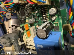
Here are photos of the transformer. The circled area is where the transformer is. On the side in black print the numbers 24408 are inscribed (near the
capacitor)
The 15 ohms where measured between the two pins that are closer to each other (the ones on the right).
[Edited on 9-7-2024 by Cendre]
[Edited on 9-7-2024 by Cendre]
|
|
|
bnull
Hazard to Others
Posts: 269
Registered: 15-1-2024
Location: Between the Atlantic and the Pacific Ocean
Member Is Offline
Mood: Sleepy (again)
|
|
Thank you very much. According to the picture at the bottom left, it is an EI30/18 2.3 VA, 29 mm high (I can now stop playing "Guess Who?"). The specifications are as given on the image below. I don't know how to enlarge
the image.
If it were working correctly, the voltage on the secondary (see image) with the unit turned on should be 12 VAC. Since only the secondary gives a
resistance value, we may safely assume that @Sulaiman was right and the primary of the transformer is damaged. You may take it out of the circuit and
measure the resistance of the primary and secondary again, just to make sure. If the resistance of the primary is nowhere near 6000 ohms*,
order a replacement.
And the capacitor is probably dead. You said the it is a little loose but on the underside the solder looks normal to me. Replace it with a 2200 uF,
35 V or higher (50 V is OK).
*: The secondary output is 12 V, 192 mA, which means 2.3 VA. Assuming and ideal transformer, we have a
current 120/12 = 10 times smaller, or ~20 mA = 0.02 A. This means a resistance of the primary equal to 120/0.02 = 6000 ohms. Sort of.
Edit: This value includes inductive reactance, which I forgot. The resistance you measure must not exceed 6000 ohms. Thanks, @Sulaiman.
[Edited on 10-7-2024 by bnull]
Quod scripsi, scripsi.
B. N. Ull
P.S.: Did you know that we have a Library?
|
|
|
Sulaiman
International Hazard
Posts: 3620
Registered: 8-2-2015
Location: 3rd rock from the sun
Member Is Offline
|
|
The primary dc resistance would have been approximately
(secondary resistance) x (turns ratio)2 = 1500 Ohms.
(turns ratio) = (voltage ratio)
(my earlier guess of 100 to 300 Ohms was based on an incorrect guess of the VA rating)
The 6000 Ohms mentioned above is a non-linear complex impedance, not easily measurable.
..........
The transformer is dead.
It looks to be a common pin-out so third party types may fit, but original is simpler and safer.
Typically the rest of the low voltage circuitry will be ok,
probably even the large electrolytic capacitor,
but replace it if there is bulging of the can or any corrosion/leakage.
(personally I'd replace it anyway while the unit is being serviced, I'd replace the smd electrolytics too, but I'm an ex service engineer with
equipment and components)
..............
You should measure the dc resistance of the heating element first,
because the replacement cost and effort would be significant.
R = V2/W = 1202/1000 = 14.4 Ohms
Similarly, check that the motor winding is ok.
..............
I'm too lazy to look - is there a schematic diagram available?
[Edited on 10-7-2024 by Sulaiman]
CAUTION : Hobby Chemist, not Professional or even Amateur
|
|
|
Cendre
Harmless
Posts: 23
Registered: 1-12-2023
Location: California/France
Member Is Offline
Mood: No Mood
|
|
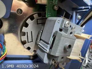
You think the heating element of the unit might be dead? How would I check it? The motor winding would be for the stirrer function right? Wouldn’t I
need to open it to check the windings? The magnet when turned manually turns unobstructed.
There are two wires going to what I guess is the heating element (in white) can I check with those? And how would I check it? Edit: I just checked the
resistance of the two wires while unplugged and got about 35ohms.
The other image is of the motor, I guess I could remove the screws but I would prefer not to move too many things from the original configuration.
[Edited on 10-7-2024 by Cendre]
[Edited on 10-7-2024 by Cendre]
|
|
|
Cendre
Harmless
Posts: 23
Registered: 1-12-2023
Location: California/France
Member Is Offline
Mood: No Mood
|
|
This is what I meant with a little loose for the capacitor. I have no idea if it is usual. None of the (way) smaller other capacitors in the circuit
do it.
Edit: while still soddered to the board and unplugged the capacitor gives continuity as does the secondary of the transformer but the primary
doesn’t.
Edit 2: looks like that transformer is “obsolete and no longer manufactured”. Is there another component I could use to replace it. I wasn’t
able to find the exact model sold anywhere.
(In Europe)
Attachment: IMG_6342.mov (5.4MB)
This file has been downloaded 17 times
[Edited on 10-7-2024 by Cendre]
[Edited on 10-7-2024 by Cendre]
[Edited on 10-7-2024 by Cendre]
|
|
|
| Pages:
1
2 |