Jenks
Hazard to Others

Posts: 150
Registered: 1-12-2019
Member Is Offline
|
|
Building an Analytical System for Plant Alkaloids
I am starting a project in a few weeks that has been on my mind for most of my adult life - there needs to be a robust, open-source system that a
hobbyist or growing professional can put together for themselves to provide analytical services. I know this sounds very general, but the specific
application I have in mind could be applied to an extremely wide variety of common problems.
In this particular case, there are a few factories that have been set up to extract voacangine from the bark of the Voacanga africana tree that has
habitat in many African countries, isolate it and have it converted into ibogaine, which is used primarily in the treatment of addiction to opiates
and stimulants. I have spent much of my life developing these processes and openly publishing the manufacturing procedures. But the process is
hampered by the lack of an easily available analytical tool to assess the amount of voacangine or ibogaine present in intermediate stages of the
manufacturing process.
So in two weeks I intend to go to Ghana and try to cobble together an analytical system using parts I have mostly amassed through eBay, mostly from
the Chinese factories that seem to have down producing electronic and related high-tech parts.
I am following the obvious course of using a low pressure chromatography column of some sort, feeding the effluent from that into a flow cell made of
quartz, passing through it a beam of ~250nm UV from a UV LED, detecting it with one of the specific UV sensors I have bought, and getting the signal
from that into a computer where I will process it in a Linux operating system environment, hopefully taking advantage of existing open-source software
to present the analytical results in a convenient format. Hopefully TSA will allow my suitcases stuffed with these supplies to pass through security
as they have graciously done in the past.
The specifics of this system are where I can use all the help I can get. I have tried to guess the best technologies to put in these bags, but,
although I have a PhD in organic chemistry I'm not even a practicing chemist and need a lot of help. I will try plain silica of course but neutral or
basic alumina seems like a good option for these alkaloids based on the literature and past experience, but there are also functionalized media that I
don't understand very well and the idea of ion exchange chromatography of the cations seems promising. Then there is GC, which has worked with these
alkaloids despite their mass. I don't have time to investigate everything. I have only five weeks in Ghana to get this together, so I need to center
on the best ideas quickly to offer the best working system to everyone when I am done. Thank you for any recommendations you find to share.
|
|
|
Sulaiman
International Hazard
Posts: 3625
Registered: 8-2-2015
Location: 3rd rock from the sun
Member Is Offline
|
|
Not my area at all, but may I suggest that someone in Ghana orders equipment and supplies for traditional wet chemical quantitative analysis as backup
/ reference.
Hopefully to arrive about the same time as you.
I guess that you have better info.
(and some members here have real expertise)
https://www.google.com/url?sa=t&source=web&rct=j&...
https://www.orientjchem.org/vol29no2/qualitative-and-quantit...
etc.
CAUTION : Hobby Chemist, not Professional or even Amateur
|
|
|
leau
Hazard to Others
Posts: 122
Registered: 3-12-2021
Member Is Offline
|
|
This document might be helpful:
https://www.researchgate.net/publication/257907428_Analysis_...
as chromatography is almost certainly your best choice.
[Edited on 3-7-2024 by leau]
Attachment: Analysis_of_alkaloids_from_different_chemical_grou.pdf (2.5MB)
This file has been downloaded 34 times
|
|
|
Anthracene
Harmless
Posts: 9
Registered: 4-12-2023
Location: Stone Island
Member Is Offline
Mood: Curious
|
|
The system you describe would take care of separation and detection
/quantification at once, pretty neat but also complex.
How about a two step approach?
First separation on a column, maybe there is a suitable SPE column solvent combination that works. You could build this from a syringe, some cotton
and a suitable stationary phase.
Then in a second step UV detection in a cuvette, like measuring OD600 of a culture.
Of course it is more tedious and requires more time to do, but it is a lot simpler to set up.
Even simpler would be a specific reagent to mix directly with the sample and then measuring the absorbance at a specific wavelength. I am thinking of
something like ferrozine for iron(II) or o-toluidine for glucose.
Edit:
Actually, looking at the molecules, they might have some unique absorption bands as they are. Maybe just putting them in a photometer might do the
trick. I did not find any good spectra with 5 min of googling but they might be published. If not, I have two spectrophotometers and could provide
them given a sample. If the goal is an open source device this might be accomplished with LEDs of specific wavelength and photoresistors. Can you
describe what kind of sample you are looking at? Raw plant material will require extraction of course.
[Edited on 3-7-2024 by Anthracene]
|
|
|
bnull
Hazard to Others
Posts: 280
Registered: 15-1-2024
Location: Between the Atlantic and the Pacific Ocean
Member Is Offline
Mood: Sleepy (again)
|
|
Quote: Originally posted by Anthracene  | | If the goal is an open source device this might be accomplished with LEDs of specific wavelength and photoresistors. |
You can even use LEDs in place of the photoresistors.
Quod scripsi, scripsi.
B. N. Ull
P.S.: Did you know that we have a Library?
|
|
|
Jenks
Hazard to Others
Posts: 150
Registered: 1-12-2019
Member Is Offline
|
|
Thanks for the article suggestion - it does look relevant, and it is even accessible! I will check it out.
My work in this area has focused on making technology more accessible in terms of price, otc availability of parts and materials and making the
system easily understandable to set up and use. Past work was on ibogaine extraction or manufacture, but I tested conditions for GC and HPLC for others to reproduce and also to put some numbers behind the production processes.
While I could make a manual process to extract and isolate voacangine and ibogaine from a sample and then quantity it spectroscopically, I imagine a
more elaborate system that would allow convenient, ongoing sample analysis compatible with the needs of the few ibogaine factories in operation today.
These tend to be run by individual chemists or small teams who have dedicated their careers to this work, and I imagine the analytical chemist being a
full time part of such a team and hopefully collaborating with other teams to meet their analytical needs.
I had to pick between gas and liquid chromatography to develop for this project, and I picked liquid mainly out of familiarity, and hopefully I won't
regret it. GC is promising for these alkaloids because I have seen it work, and it may be very selective because many of the alkaloids needing to be
separated are dimeric or of higher molecular weight.
I envision this system delivering solvent at a known, controlled flow rate, either utilizing a pump such as a peristaltic or syringe pump or by measuring the flow rate, perhaps by counting drops optically, and using something like a solenoid valve to control the flow.
The procedure I remember using to prepare samples for HPLC was to weigh 10-20 mg of plant or solid alkaloid mixture directly into each of three 10 mL
volumetric flasks, fill with methanol, sonicate, filter through a syringe filter disk, then dilute to the proper analytical concentration using a
micropipetter and another volumetric flask.
Since this chromatography would operate close to or at atmospheric pressure, the column would be larger than an HPLC column and the injected volume to
be analyzed would be around 0.1-1 mL, which might be measurable using a standard hypodermic syringe, provided that the plastic it is made of is
compatible with the solvent injected. Perhaps it could be injected through a rubber septum into the line leading to the column, or even into a rubber
tube carrying the solvent.
The column could be a small conventional column or a prepackaged one. For the detector I bought a Gilson 111 UV detector, but I plan to compare that with building a flow cell detector using a 1mm quartz flow cell with a 250 nm UV LED, comparing various detectors such as this photodiode or a UV detector module. Since these alkaloids absorb UV longer than 254 nm because of their bicyclic indole system, a 270 nm UV LED and detector can
be added to the same flow cell and may allow some distinction of which alkaloid is passing through. I plan use a Raspberry Pi to process and integrate
the signal from the detector since I am familiar with using them, and that same Pi can be used to manage solvent flow rate and any other automated
features of the system.
The quartz flow cell is expensive, so although I sprung for one I would still like to try my original idea of fabricating one by cutting the bottom
off a 1mm quartz cuvette and attaching tubes to the ends, or even just using quartz tubing itself.
Finally, I am playing with the idea of automatically recycling the solvent by continuous distillation, perhaps using a Peltier module and a pair of CPU cooling blocks to distill eluent from the hot side of the module to the cold side.
[Edited on 4-7-2024 by Jenks]
|
|
|
Anthracene
Harmless
Posts: 9
Registered: 4-12-2023
Location: Stone Island
Member Is Offline
Mood: Curious
|
|
I looked at your homepage and I am really impressed. It is fascinating how dedicated you have been over the years and how much research you have done
for this cause. I see now that you are dealing with quite complex mixtures of alkaloids, so you definitely will need a chromatography step.
For the pumps I think a syringe pump is the best option. Both peristaltic and syringe pumps are theoretically suited but especially the cheap
peristaltic pumps produce fluctuating pressure. You could try to get away really cheap with a big syringe actuated by a spring or rubber bands.
The idea to use UV LEDs and UV index detector modules is great, potentially this could be a ridiculously cheap UV detector. Are you sure that the 2 mm
path length is enough though? I am sure you have some actual data on how well these molecules absorb in the given wavelength. During my lunchbreak
today I found out that quartz discs can be purchased for a small price, maybe a chamber resembling a commercial UV detector module could be
fabricated? Basically a tube with a quartz disc and a rubber seal on either side. This way you could get a path of an inch or more.
The idea of recycling solvents is great, but it seems to me that collecting over a bunch of samples followed by simple destillation is more straight
forward than an automated continuous system.
I wish the best of luck to you and your project in Ghana!
|
|
|
Jenks
Hazard to Others
Posts: 150
Registered: 1-12-2019
Member Is Offline
|
|
Thank you, Anthracene, for your feedback and encouragement - it goes a long way. I bought two rather heavy Tecan Carvo syringe pumps. If I can figure
out how to get them working, I agree with you that they should at least be designed to provide a more measured flow rate. The potential problems are
that neither these nor the peristaltic pumps are designed to pump organic solvent - the peristaltic pumps being only as compatible as the probably
silicone tubing they came with - so I am on my own to assess compatibility. And while syringe pumps are the technology that provide continuous,
measured, high-pressure flow for HPLC, those have two syringes pumping in tandem to accomplish that. Since my repurposed pumps have only single
syringes, it is not physically possible for them to provide continuous flow unless I employ a buffering system, but then that system would require the
actual flow per minute to be calibrated.
As for the flow cell path length, these are actually 1mm, not 2mm, which I selected to reduce the size of column needed to have the peaks of interest
be contained within the volume of the flow cell. But in case the path length is inadequate, I bought several standard 1cm quartz cuvettes I can cut
the bottoms off to fabricate 10mm path length flow cells. I also have a sheet of UV filter glass I can cut up to fabricate flow cells the shape I want. I don't know why that sheet is much cheaper per unit area than the quartz
disks you mention, or why any quartz on eBay seems much more expensive than oven door window material, unless I am missing something.
My main constraint seems to be having few choices of chromatography media to test. Even the pre-packaged amine-functionalized medium I linked to above was lost by the seller and refunded, so all I have to test are silica gel and some neutral alumina I can bring. I should have
invested in some C18 cartridge but I didn't see anything at a reasonable price when I had the chance, and the point of my system is to bring the price
of it within reach of us mere mortals.
I have to agree that for an analytical system, maybe it adds unnecessary complexity to recycle solvent automatically. Two more reasons I want to do
this are that it would allow time to leach off any crud on the column that might be detectable so that the column can be used as long as it keeps its
ability to separate components. The other thing is that I would like to be able to use this same technology to automate production chromatography,
using the aforementioned solenoid valves for sample collection. I suppose with only six weeks to work I must be dreaming, but if I can sufficiently
inspire an apprentice, maybe they can fulfill the vision after I am gone.
[Edited on 5-7-2024 by Jenks]
|
|
|
Jenks
Hazard to Others
Posts: 150
Registered: 1-12-2019
Member Is Offline
|
|
A little update - I have arrived Safely in Ghana with myself and my copious supplies intact. Another little good news is that the person I am working
with here happens to have basic alumina available, so this will add a third chromatographic medium to the silica gel and neutral alumina I already
can test. I will post again when I have something interesting to report.
|
|
|
Jenks
Hazard to Others
Posts: 150
Registered: 1-12-2019
Member Is Offline
|
|
So far I have successfully connected the Raspberry Pi A I brought to my Ubuntu laptop through an ethernet switch not connected to a local or external
network, but internet access was provided by the Pi through the laptop. If anyone would like details on how this was done, please ask.
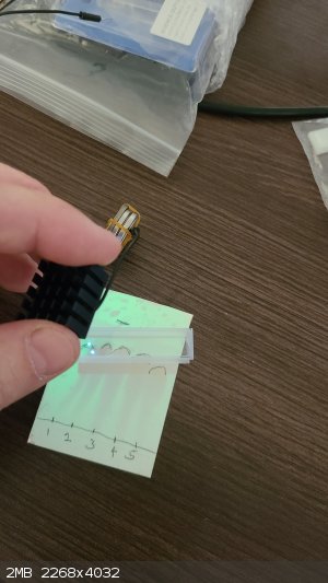
I have also started testing the 250 nm UV LEDs that I bought. One is 0.1 watt with no lens, with an unspecified wide angle, on a 16mm board, rated at 6-7 volts at 0.1 amps. This was attached to a heat sink using thermal glue. I found that it just barely started shining at 5 volts as shown here:
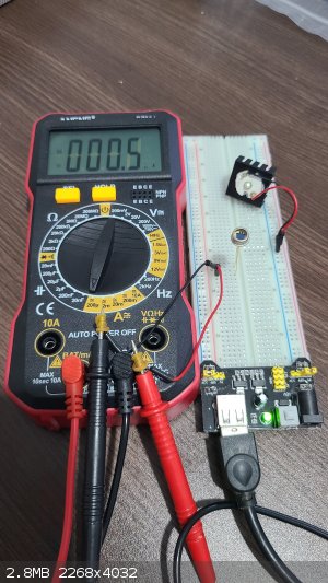
The meter is showing the current produced by an OSI Optoelectronics UV-015 Inversion Layer UV Photodiode, 0.5 microamps in ambient light. When I expose the photodiode to the faint 250 nm UV from
the LED, I get 33.8 microamps:
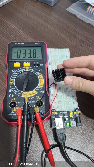
So my initial plan is to place the LED and photodiode on either side of a quartz flow cell to create a detector for aromatic organic compounds flowing
through in solution.
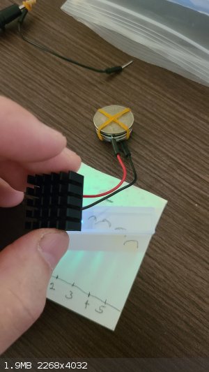
I also wanted to make a 250 nm UV lamp for my friend Affo to use to visualize TLC. The LED above isn't bright enough even at seven volts. However, a
1W LED with a lens giving a 60 degree beam is sufficient:
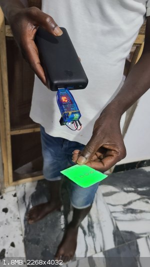
The blue voltage converter is raising the 5 volts of the battery bank to 6.2 volts for the LED, and is adjustable using the gold knob of the trimmer. I was
happy with the cost of this setup, as the voltage converter cost $5.65, the LED was $13.69 and the heat sink was $0.35, for about $20 total.
|
|
|
Jenks
Hazard to Others
Posts: 150
Registered: 1-12-2019
Member Is Offline
|
|
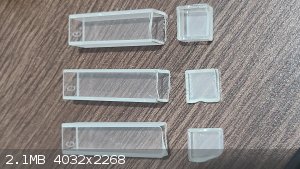
I got around to testing the cuvettes and the flow cell that I bought for this project. What I purchased from eBay are four 1cm quartz cuvettes from chenting2018, one 1cm quartz cuvette from osag7667, one 1mm quartz cuvette from labsciware and one expensive 1mm quartz flow cell from quartzcrystal. I mention the vendors because of the problem I discovered with the four 1cm "quartz" cuvettes from chenting2018:
As you can see, the 250nm UV from the LED is not penetrating the cuvette, so that a shadow is cast on the TLC and only the UV going past the cuvette
is causing it to fluoresce. In contrast, the 1cm quartz cuvette from osag7667 transmits UV properly:
Thankfully, the more expensive and useful 1mm cuvette and 1mm flow cell transmit UV like the single 1cm quartz cuvette that I have. My intention with
the cuvettes, to make them into flow cells, it to cut off the bottoms with a Dremel carbide cutting disk and attach glass tubes to the ends using
polyolefin heat shrink tubing, which I hope will seal, be inert, and not swell when exposed to solvent.
|
|
|
Jenks
Hazard to Others
Posts: 150
Registered: 1-12-2019
Member Is Offline
|
|
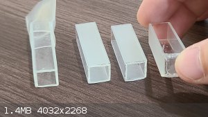
I tried cutting the ends off three of the four glass cuvettes with a carbide disk on a Dremel:
The first one, at the bottom, I started on one corner and the bottom shattered off uncleanly, but at least there are no cracks on the body of the
cuvette. For the middle one I tried working my way repeatedly around the cuvette, with the thinking that when the bottom cracks off that the crack
would follow the scoring line. This seemed to work, but there is a crack coming up from one corner that could eventually cause the cuvette to shatter.
After reading and watching everything I could find online about cutting quartz tubing, I tried dipping the cuvette into water every few seconds as I
worked by way around the cuvette. The cracks seem to follow the cut lines better, but maybe I was lucky, and the job is still ugly because I can't
follow the same line repeatedly while holding the tool and the piece by hand.
Can anyone offer advice on a better way to do this? I have one more glass cuvette to practice on before I turn to the two quartz cuvettes. Scoring and
thermally stressing, I am told, doesn't work well for quartz due to a lower coefficient of expansion. One thing I could try is grinding the bottom off
the cuvette with an abrasive wheel. I don't mind if it takes an hour, but I am concerned that the long grinding would only increase the chance of
cracking, and I couldn't find any online material aside from grinding quartz countertop or faceting quartz stones.
|
|
|
bnull
Hazard to Others
Posts: 280
Registered: 15-1-2024
Location: Between the Atlantic and the Pacific Ocean
Member Is Offline
Mood: Sleepy (again)
|
|
Try sandpaper. It sounds ridiculous, but here it is: make small disks from sandpaper, attach them to the Dremel, and grind only the regions where the
bottom unites with the walls.
The kind of sandpaper I use is waterproof silicon carbide for metal, usually black or gray. Grains 80, 150, 320 and, if really needed, 1500. But
usually I can get away without this one and it may be a little hard to find. The sandpaper goes on top of a metal disk or that cutting disk you said,
with a rubber disk between them. The rubber (from a bicycle inner tube, for example) is to minimize physical shock.
Use a low speed and water to wet the disks and wash the cuvette every now and then.
Begin by grinding the bottom at the edges at an angle (45° is good enough). Use first the 80, then 150 and finally 320. Change from one grain to
another when you see that the surface is smooth enough and is not being ground anymore. When the bottom falls off, grind the edges until they're all
plane and parallel.
I feel that I'm forgetting something. Edit: Ah, yes. Try at first with those three little boxes you cut out of the cuvettes.
By the way, what is the thickness of the cuvettes?
[Edited on 19-7-2024 by bnull]
Quod scripsi, scripsi.
B. N. Ull
P.S.: Did you know that we have a Library?
|
|
|
Jenks
Hazard to Others
Posts: 150
Registered: 1-12-2019
Member Is Offline
|
|
Thanks for the reply, bnull. Both quartz cuvettes have 1mm thick walls but the glass ones are 1.25mm according to the questionable seller, but that
looks right. I have sanding disks I can install on rubber disks backed by the carbide wheel. I don't know what grit these disks are, as the contents
listed on the rotary tool accessory kit doesn't even list the sanding disks. We are having our first power failure now since I arrived, so I will wait until
after to test the sanding.
I hope to use polyolefin heat-shrink tubing to connect each cuvette to tubing to create the flow cell, and that I will find the polyolefin tubing to share some
of the chemical resistance of polypropylene and polyethylene.
Update:
I tried the sanding disks but they weren't very effective. I also tried the side of the cutting disk as the sanding disk but it shattered along with
breaking a few more chips off the end of the cuvette. So I tried the 1/2" sanding band (of unknown course grit) on the rubber mandrel and this worked
amazingly well to grind down the uneven edges of the three glass cuvettes from yesterday, as well as leaving a clean smooth edge without introducing
any cracks. I wasn't able to get the edge completely flat but I didn't really try and figured what I got was good enough.
So I confidently tried grinding down the bottom edges of the last glass cuvette, planning to continue until the bottom of the cuvette became detached
from the sides. At this point I should mention my concern with the invisible cloud of silica I must be generating that I should not inhale. Not having
a mask available, I worked outside with the wind at my back and got into a rhythm of dipping the piece in water, inhaling, then working one edge of
the cuvette back and forth against the band, working my way down from top to bottom, at about a 30 degree angle vs. the bottom, for about half a
minute until time for another breath. Unlike the cutting disk, this felt very gentle, and I used little force between the sander and the cuvette. It
seemed to take about an hour until I figured I was nearly done, when I noticed cracking:
What seems to be happening is that as the glass along the edge of the base becomes very thin, cracks form along the thin edge that can continue into
the bulk of the glass, and have propagated into the cuvette, making this the most unsound of the jobs so far. I think the best method, based on what I
have learned so far, is to work my way around the base of the cuvette with the cutting disk to lead cracks along that path, take the uneven cut I get,
then grind the bottom end as flat as possible with the sander, which will smooth it.
[Edited on 19-7-2024 by Jenks]
|
|
|
bnull
Hazard to Others
Posts: 280
Registered: 15-1-2024
Location: Between the Atlantic and the Pacific Ocean
Member Is Offline
Mood: Sleepy (again)
|
|
It was an idea. 
Quod scripsi, scripsi.
B. N. Ull
P.S.: Did you know that we have a Library?
|
|
|
Jenks
Hazard to Others
Posts: 150
Registered: 1-12-2019
Member Is Offline
|
|
It was a good idea, and I appreciate it. It was useful to even out the end of the cuvette, so I will still use it.
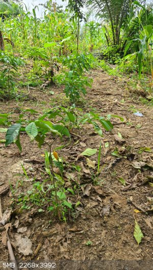
This is an iboga farm I visited today on the outskirts of Accra, Ghana. It wasn't known until a few years ago, as far as I know, that iboga could be
cultivated in Ghana, since it is usually found in Gabon and Cameroon. This farm is relevant to this thread because it is the alkaloids from the bark
of these shrubs, and related Voacanga africana trees, that are to be analyzed with the proposed system.
|
|
|
Jenks
Hazard to Others
Posts: 150
Registered: 1-12-2019
Member Is Offline
|
|
I've made a little progress in the last four days.
The Arduino IDE was installed on the Ubuntu 24.04 workstation simply by installing the "arduino" package from the command line:
sudo aptitude install arduino
Right off I couldn't find it among the serial ports. This turned out to be due to a conflict with a braille e-reader, as explained in this StackExchange post, and was removed with the command:
sudo apt remove brltty
At this point, what I have done is to connect two of the analog inputs of the Arduino Uno to two of the UV photodiodes which will measure the UV
passing through the finished quartz flow cell from a 250 nm LED and a 270 nm LED. The power for the LEDs is controlled by two of four relays on a relay module, which itself is controlled by two of the digital outputs on the Arduino. A digital input on the Arduino is connected to a pushbutton
switch which is connected between a 100k and 1M resistor so that if that digital input should fail to be configured as an output, the output won't
draw enough current to burn it out.
The power supply for the UV LEDs was a challenge. I didn't realize that the two kinds of small voltage converters I bought only step voltage down, not
up, so that the five volts from the Arduino can't drive the LEDs. I built the IC 555 Voltage Doubler Circuit with High Current Output described as
project #6 here, but although it converted five volts to 7-8 volts without any load, with the load of the UV LEDs the voltage dropped to five volts. I had to
substitute S8080 and S8550 transistors for the BD139 and BD140 transistors proposed in the design.
Since that didn't work, and the shipping time to order any electronics exceeds the time left for the project, I was glad to be offered a broken TV to
cannibalize for its main circuit board, which apparently includes a regulated 12 volt power supply. That was attached to a power converter I have, which I adjusted to get 6.63 volt output:
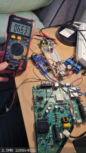
When I turn on the LEDs using the aforementioned button, the voltage only drops to 6.53 volts:
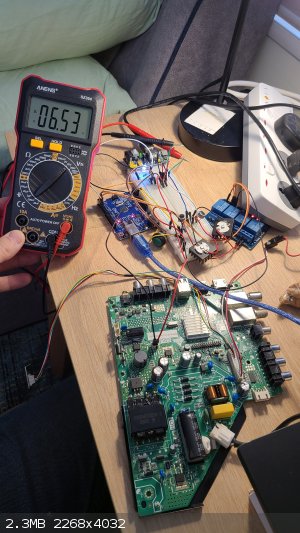
A couple nasty things about this TV board are that the big capacitor there charges to 330 volts to run the switching power supply, but retains its
charge when the unit is unplugged. I soldered a 1M resistor across the capacitor so that the voltage drops about 2 volts/second after unplugging. I
also discovered with only a minor shock that the 12 volt plug on this board is apparently not isolated from the mains, and that the ground pin on the
power plug is made of plastic. The voltage step-down module also doesn't isolate input from output. So I have to be careful, and hopefully find a nice
wall-wart to use instead in the final design.
So it looks like this system is ready to put in a box. I know it is minimal, but I have to get this thing working and people trained to use it before
I can make it any nicer.
[Edited on 24-7-2024 by Jenks]
|
|
|
bnull
Hazard to Others
Posts: 280
Registered: 15-1-2024
Location: Between the Atlantic and the Pacific Ocean
Member Is Offline
Mood: Sleepy (again)
|
|
Try a pair of old PC speakers. Their power supply gives 9 V (or 12 V, depending on the model), and you can even use the enclosures to house your
system: Arduino inside the one with the PSU, and the rest of the system inside the other.
Quod scripsi, scripsi.
B. N. Ull
P.S.: Did you know that we have a Library?
|
|
|
Jenks
Hazard to Others
Posts: 150
Registered: 1-12-2019
Member Is Offline
|
|
Thanks for the suggestion. I will look for that. I recently happened to scour a few Goodwill stores near my Sacramento, California area home for
computer speakers and their power supplies to help a few high school students in my wife's physics classes with building Rubens tubes and a wine glass
shattering demo. Their power supplies tended to be 5-9 volts. My constraints here in Ghana are a much different retail selection, and a much more
significant hazard in making long trips by car.
I had hoped to import the completed chromatographic data, read in real time from the arduino by a PHP program and saved as a simple comma-separated
values (CSV) file, into OpenChrom, which seems to be the predominant open-source chromatography software recommended for Linux systems. I am stuck now
in figuring out how to simply find and open the .csv file from OpenChrom, as, despite its name, it seems to expect me to select one of a variety of
proprietary chromatography or mass spectrometer data formats to import from, none of which I can recognize as having a simple liquid chromatography
data format. If anyone has experience with this software and can help me, please post here or contact me through the messaging system. Thanks in
advance. The help I could find online was extremely limited.
[Edited on 25-7-2024 by Jenks]
|
|
|
Sulaiman
International Hazard
Posts: 3625
Registered: 8-2-2015
Location: 3rd rock from the sun
Member Is Offline
|
|
1) A usb supply + 'power bank' form a nice 5V dc ups for low power.
2) 12V dc at high power can be had from an automotive battery + charger
3) 19V at fairly high power can be obtained from a laptop charger
4) Many voltages at high power are available from desktop PC power supplies.
In order of safety, 3),1),4),2)
................
PS using solar/hydro/wind power may win some points as a 'green' agenda?
(B.S. but some folk fall for it 
[Edited on 26-7-2024 by Sulaiman]
CAUTION : Hobby Chemist, not Professional or even Amateur
|
|
|
|