Admagistr
Hazard to Others
  
Posts: 373
Registered: 4-11-2021
Location: Central Europe
Member Is Offline
Mood: The dreaming alchemist
|
|
Very cheap 400KV,DC HV generator
I discovered this Chinese high voltage DC step up module 400KV on the market,you just need to connect it to a lithium battery and it is really
very,very cheap! I have tried it and it produces very bright sparks with a very strong sound effect.Almost everywhere it says that it generates
400KV,but I found out that this value is exaggerated and the real value of the voltage it generates is only about 8.2KV. It is commonly sold but also
the one where the manufacturer states the value of 1000KV.It is possible at least theoretically to connect in parallel or in series more such modules
together! I have seen a successful implementation of an alpha particle detector, on YouTube by Ludic Science, in which the source is one of these
weaker HV step up modules! Has anyone tried to build something interesting out of it,like an X-ray tube,cathode ray tube...?I was thinking that it
could be used to make a linear accelerator,if more modules were connected in series,to power an atmospheric-nitrogen laser,a Co2 laser,but I'm not an
expert in electrical engineering,so I don't know how realistic my ideas are.I'll be glad if you write what could be done with it;-)
https://www.amazon.com/400000V-Step-up-Module-High-Voltage-G...
|
|
|
Fery
International Hazard
    
Posts: 1026
Registered: 27-8-2019
Location: Czechoslovakia
Member Is Offline
|
|
I'm not expert in electricity but from the picture with such wires so close together and such poorly insulated I don't believe it would withstand 0,4
or even 1 MV. Piezoelectric igniter gives 10+ kV and the spark jumps over few mm distance in air like a charm.
|
|
|
wxyz
Harmless

Posts: 20
Registered: 13-4-2010
Member Is Offline
Mood: No Mood
|
|
I note that the description of the device now says "400KV 400000V" so it could be anywhere in that range. There are actually many such devices on
amazon, I have been tracking then on and off for a fee years now. The better ones can reliably produce 5KV from a battery for a similar price (about
5-10$). I was thinking of buying maybe 20, maybe even 100 some day, and connecting them in series. This is only possible because they are battery
powered, so there are no other electrical connections between each module than the one series wire. There are many other HV considerations as well,
like they would need to placed on a dry non-conducting surface, sort in a large semi circle. But in theroy the voltage produced is only limited by the
number of them.
OH, there one big problem that needs to be solved with the about scheme: you need a wireless or light activated way to turn them all on or off at
once. For me light activated is easient: put in the batteries with the lights out, at night, then tun on the lights and let her rip. But yeah, you
need 20 or 100 such light controled modules, one for each mini HV supply.
|
|
|
Admagistr
Hazard to Others
  
Posts: 373
Registered: 4-11-2021
Location: Central Europe
Member Is Offline
Mood: The dreaming alchemist
|
|
Is this unit Cocroft-Walton generator with transistor?
https://www.youtube.com/watch?v=_Zs8nox4QoA&t=3s
https://www.youtube.com/watch?v=j8HPp016GOo
https://www.youtube.com/watch?v=XI2p6SeXneE
[Edited on 20-12-2022 by Admagistr]
[Edited on 20-12-2022 by Admagistr]
|
|
|
violet sin
International Hazard
    
Posts: 1482
Registered: 2-9-2012
Location: Daydreaming of uraninite...
Member Is Offline
Mood: Good
|
|
I built the cheapest one I could find 2.72$ off wish, 3$ S/H .. 6.16$ total so it was only cheap in theory. Stated to be 15KV.
https://www.wish.com/product/5ad42d20da00373253947d3b
It makes a decent spark off usb 5v cord power. But if the sparking contacts are too far apart, it starts trying to arc over on the transformer leads
at the PCB, and the directions are absolute garbage. Lining up winding direction to board holes is hit or miss for some. There were a number of
videos from people who figured it out. Still cheap and works.
Was going to implement a HV trigger start to a dumb stick welder. Classic transformer guy, sturdy and capable. I'm not that good at all yet, lot of
dirty starts. The HV source looks to be fun for small scale play, prob needs some large capacitor to charge to do real work, and definitely needs to
be submerged in oil. ( The one you linked looks sealed). Not sure how it would do across a vacuum tube, my understanding of the effects says there
may be some x-ray emissions but 15KV is pretty low so IDK.
I have an ignition transformer for an oil burning furnace, is far more fun to play with for bigger projects. Years ago It made a quart jar brown
pretty quick with platinum electrodes and it's 8-10KV. voltage tripler and rectify it was some fun experience. Few magnets to see how effective you
could spread/shape the arc. Pretty dangerous way to play, be safe of course. Sure illustrates forces at work, made for good sketches and notes.
Here's a 6KV DC build vid I found couple days back. I bet it would do just fine with pumping other stages for really High Voltage. I've never needed
that kind of tension though. Sounds much less safe for casual play. Stay focused.
https://m.youtube.com/watch?v=OBQTBgFjFsQ
|
|
|
Sulaiman
International Hazard
    
Posts: 3722
Registered: 8-2-2015
Location: 3rd rock from the sun
Member Is Offline
|
|
Microwave oven transformers scare me.
I've multiple experiences with high voltages,
both professionally and hobby
(Tesla coils, voltage multipliers, Marx generators, neon and oil ignition transformers etc.)
Electronics wise, the only thing that scares me more than microwave oven transformers is high voltage capacitor banks.
So
unless you really need a potentially lethal power supply,
Please stick to low power supplies.
CAUTION : Hobby Chemist, not Professional or even Amateur
|
|
|
Kidsysticks
Harmless

Posts: 1
Registered: 18-11-2022
Location: western EU
Member Is Offline
Mood: good, I think
|
|
I've built a nitrogen/air laser with one of those for a schoolproject, and that worked decently enough.
I don't think these a powerful enough to drive a whole X-ray tube though, since the voltage output isn't really constant. Maybe one of those neon sign
tranformers might be a better choice, as they are relatively cheap and produce a more stable voltage.
|
|
|
Sir_Gawain
Hazard to Others
  
Posts: 457
Registered: 12-10-2022
Location: [REDACTED]
Member Is Offline
Mood: Stable
|
|
I used one of these things in my EBW setup. With a 1 microfarad microwave capacitor that has a 10 megaohm bleed resistor, the voltage stabilizes at 4
kv. It works great.
As far as the circuitry of the hv modules, they contain a simple transistor driven flyback like this; https://www.ebay.com/itm/223441591883?chn=ps&mkevt=1&...
and a voltage doubler.
“Alchemy is trying to turn things yellow; chemistry is trying to avoid things turning yellow.” -Tom deP.
|
|
|
Admagistr
Hazard to Others
  
Posts: 373
Registered: 4-11-2021
Location: Central Europe
Member Is Offline
Mood: The dreaming alchemist
|
|
That sounds great,I've always wanted to try this method,is it difficult to build such a device?Do you have any YouTube videos or instructions;-)?
|
|
|
yobbo II
National Hazard
   
Posts: 764
Registered: 28-3-2016
Member Is Offline
Mood: No Mood
|
|
They are like a flyback transformer from an old (tube type) TV set.
Yob
|
|
|
Admagistr
Hazard to Others
  
Posts: 373
Registered: 4-11-2021
Location: Central Europe
Member Is Offline
Mood: The dreaming alchemist
|
|
I found this very interesting site,describing the design of a TEA atmospheric nitrogen laser,where the HV source is our discussed step up HV-DC module
"400KV."
https://jarrodkinsey.org/011321/
|
|
|
Mateo_swe
National Hazard
   
Posts: 548
Registered: 24-8-2019
Location: Within EU
Member Is Offline
|
|
Im sorry to inform you that those cheap 400kV HV modules never produce anything near those voltages specified.
You will never get more than maybe 40kV at very maximum, probably less, and its very small current.
If you want more than 20-30kV you can get a flyback transformer (from an old monitor or TV, thick kind) and thake that 20-30kV output and make a
HV-multiplier using HV-capacitors and HV diodes.
Search on net, lots of info about it.
If you want more than 50kV you need to put the HV multiplier submerged in oil or encase it in expoxy, othewise the HV will jump across the capacitors
and you will not get the desired HV.
Old car ignition coils are good for maybe 50kV.
Neon sign transformers are good for HV also.
Dont try microvawe transformers, they are leathal.
|
|
|
Sir_Gawain
Hazard to Others
  
Posts: 457
Registered: 12-10-2022
Location: [REDACTED]
Member Is Offline
Mood: Stable
|
|
Admagistr:
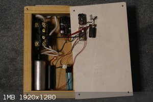
The EBW setup

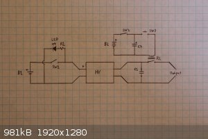
Circuit diagram

B1 is a 3.7 v 18650 battery that powers the hv module.
SW1 is the CHARGE switch.
The LED is to show it's charging, R1 is a 200? ohm resistor.
C1 is the microwave capacitor. It has a built-in 10 mega ohm resistor, and with one 18650 powering the hv module the voltage reaches about 4kv before
the resistor bleeds it away faster than it can charge.
B2 is two 9v in series to trigger the relay (RL). Two 9v weren't quite enough to fire the relay, so I added some electrolytic capacitors(C2).
SW2 is the firing mechanism arming switch. If you connect the capacitors (C2) directly to the batteries they will eventually drain them.
RL is a heavy-duty relay from a HVAC unit. I originally used a trigatron I built, but it was unreliable. The relay takes a lot of damage, so I'll
probably have to replace it someday.
SW3 is the FIRE button.
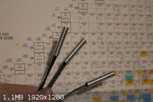
Here are the detonators:

They contain 0.5g ETN melt-cast, 0.25g pressed, and 0.25g very low-density, fluffy ETN.
The tubes are 1.5in x 9/32in OD. The inner diameter is just over 1/4 in. The bridgewire head is a 1/4 in section of 1/4 in acrylic rod. Two small
holes are drilled through it and wires fed through and glued in place. A piece of 40 awg copper wire is soldered across the two wires.
One end of the tubes is plugged with about 1/16 in of pressed aluminum foil and 0.5g ETN is pressed on top. The ETN is melted by lowering the
detonators into hot water, then letting them cool. Once the ETN is cooled, 0.25g powdered ETN is pressed on top. Then 0.25g of low density ETN is
poured in and the bridgewire assembly is inserted, leaving about 1/4 in space to fill with epoxy.
These caps are extremely powerful, and I've never had any fail. Also, they only cost about 25 cents each!
When I make more detonators soon I can post pictures if you're interested.
This guy has a similar setup:https://www.youtube.com/@freepatentsonline/videos
“Alchemy is trying to turn things yellow; chemistry is trying to avoid things turning yellow.” -Tom deP.
|
|
|
Sulaiman
International Hazard
    
Posts: 3722
Registered: 8-2-2015
Location: 3rd rock from the sun
Member Is Offline
|
|
Some good high voltage information
https://www.stevehv.4hv.org/
CAUTION : Hobby Chemist, not Professional or even Amateur
|
|
|
Admagistr
Hazard to Others
  
Posts: 373
Registered: 4-11-2021
Location: Central Europe
Member Is Offline
Mood: The dreaming alchemist
|
|
Quote: Originally posted by Sir_Gawain  | Admagistr:
The EBW setup
Circuit diagram
B1 is a 3.7 v 18650 battery that powers the hv module.
SW1 is the CHARGE switch.
The LED is to show it's charging, R1 is a 200? ohm resistor.
C1 is the microwave capacitor. It has a built-in 10 mega ohm resistor, and with one 18650 powering the hv module the voltage reaches about 4kv before
the resistor bleeds it away faster than it can charge.
B2 is two 9v in series to trigger the relay (RL). Two 9v weren't quite enough to fire the relay, so I added some electrolytic capacitors(C2).
SW2 is the firing mechanism arming switch. If you connect the capacitors (C2) directly to the batteries they will eventually drain them.
RL is a heavy-duty relay from a HVAC unit. I originally used a trigatron I built, but it was unreliable. The relay takes a lot of damage, so I'll
probably have to replace it someday.
SW3 is the FIRE button.
Here are the detonators:
They contain 0.5g ETN melt-cast, 0.25g pressed, and 0.25g very low-density, fluffy ETN.
The tubes are 1.5in x 9/32in OD. The inner diameter is just over 1/4 in. The bridgewire head is a 1/4 in section of 1/4 in acrylic rod. Two small
holes are drilled through it and wires fed through and glued in place. A piece of 40 awg copper wire is soldered across the two wires.
One end of the tubes is plugged with about 1/16 in of pressed aluminum foil and 0.5g ETN is pressed on top. The ETN is melted by lowering the
detonators into hot water, then letting them cool. Once the ETN is cooled, 0.25g powdered ETN is pressed on top. Then 0.25g of low density ETN is
poured in and the bridgewire assembly is inserted, leaving about 1/4 in space to fill with epoxy.
These caps are extremely powerful, and I've never had any fail. Also, they only cost about 25 cents each!
When I make more detonators soon I can post pictures if you're interested.
This guy has a similar setup:https://www.youtube.com/@freepatentsonline/videos |
Hi,I thought you were interesting into electron beam welding,but this is also very interesting and something new for me,I will be glad,when you send
some photos,at least I will learn something new,thanks a lot!
|
|
|
Admagistr
Hazard to Others
  
Posts: 373
Registered: 4-11-2021
Location: Central Europe
Member Is Offline
Mood: The dreaming alchemist
|
|
Great! Thanks!
|
|
|
Admagistr
Hazard to Others
  
Posts: 373
Registered: 4-11-2021
Location: Central Europe
Member Is Offline
Mood: The dreaming alchemist
|
|
Speaking of strong HV sources, I have a question for the experts, could a Marx generator be powered by two Van de Graaff generators that would supply
the same amount of charge of opposite polarity? Or is the problem that the VDGs supply a tiny current and it would not work?Thanks!
|
|
|
Sulaiman
International Hazard
    
Posts: 3722
Registered: 8-2-2015
Location: 3rd rock from the sun
Member Is Offline
|
|
I'm not an expert but I think that the leakage of the capacitors plus corona leakage would be greater than the VDG current,
unless you make the VDG and Marx generator of dimensions so large and well insulated that you'd need an Amazon warehouse filled with SF6 or
similar.
Two VDG of opposite polarity would have the bottom end of the Marx generator floating,
so one VDG would be better.
In general, potting hv generators in epoxy, silicone etc. is good for commercial products but has two main drawbacks ;
Poor thermal conductivity and
the inability to repair / replace damaged components.
Oil is messy but allows repair / modifications.
CAUTION : Hobby Chemist, not Professional or even Amateur
|
|
|
Brightthermite
Hazard to Others
  
Posts: 133
Registered: 26-6-2019
Member Is Offline
|
|
Quote: Originally posted by Sir_Gawain  | Admagistr:
The EBW setup
Circuit diagram
B1 is a 3.7 v 18650 battery that powers the hv module.
SW1 is the CHARGE switch.
The LED is to show it's charging, R1 is a 200? ohm resistor.
C1 is the microwave capacitor. It has a built-in 10 mega ohm resistor, and with one 18650 powering the hv module the voltage reaches about 4kv before
the resistor bleeds it away faster than it can charge.
B2 is two 9v in series to trigger the relay (RL). Two 9v weren't quite enough to fire the relay, so I added some electrolytic capacitors(C2).
SW2 is the firing mechanism arming switch. If you connect the capacitors (C2) directly to the batteries they will eventually drain them.
RL is a heavy-duty relay from a HVAC unit. I originally used a trigatron I built, but it was unreliable. The relay takes a lot of damage, so I'll
probably have to replace it someday.
SW3 is the FIRE button.
This guy has a similar setup:https://www.youtube.com/@freepatentsonline/videos |
How much current does your HV module draw? I have a similar one and it struggles to charge the same cap to 2kV. Output current of my module must be
low.
|
|
|
Morgan
International Hazard
    
Posts: 1705
Registered: 28-12-2010
Member Is Offline
Mood: No Mood
|
|
I bought 5 of those potted spark modules for 10 dollars and free shipping several years ago. They're pretty poppy but they don't have a long duty
cycle and can fry if run for very long. Some of the somewhat more expensive ones make a 5 cm spark. I had one of those too.
Buzz coils are good for some things. Here's one in wood and one cased in black plastic. I used them for starting my pulsejets and are quite happy to
buzz for long periods of time. The little EMCO spark unit (Danger High Voltage) runs on up to 15 volts and puts out 10,000 volts DC.
https://www.pulse-jets.com/phpbb3/download/file.php?id=12866...
And this 33 centimeter high voltage made by rubbing a paper towel over a length of pvc tubing.
https://www.pulse-jets.com/phpbb3/download/file.php?id=14229...
Cheap High Voltage
http://amasci.com/static/foster1.html
[Edited on 30-10-2023 by Morgan]
|
|
|