| Pages:
1
2
3 |
Aurium
Harmless

Posts: 46
Registered: 4-10-2015
Member Is Offline
Mood: Energetic
|
|
Spark Gap Detonators for ETN
SGD
Hi everyone,
I'm happy to be joining the forum for my first post.
I'v been making and experimenting with ETN during these summer vacations, working at my simple home lab as a hobbyist.
I came across the idea of detonating ETN with a EBW detonator (Exploding Bridge Wire), I decided to give a try to the concept after failing to ignite
my ETN with simple resistive pyro igniters.
Reading around the web and the forum on the look for a theory about the mechanism of an EBW, I developed my own theory, that the thin wire itself was
not the igniting mechanism, but instead it was the very hot and very conductive plasma gap created after the wire vaporizes that triggers the
explosive.
I then made a device, similar to the EBW, but with no thin wire, expecting a spark gap to generate between two electrodes and initiate the ETN.
##########################################
I was successful, here is my setup:
I bought a timer relay module on ebay *link*,
a High Voltage module *link*
and as capacitors I used first a microwave oven capacitor (MOC), 1uF rated 2200V, then regular electronics film pulse capacitors (3*0.33uF 850V in
series) .
The detonators were essentially a thin (~3mm) plasting tube cut to 2cm length.
First I inserted the two leads, electronics unifilliar wire cut 5mm bare at the tip, inserted at opposite sides of the tube and hot-glued to place.
Then I filled the inside with ETN, using not much pressure to stuff it in, and capped it with thigh duct tape. All done.
Each of these takes some 10min to make.
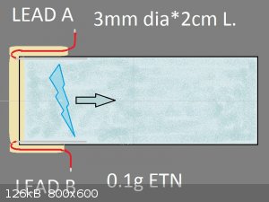
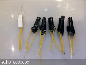
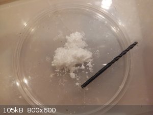
The detonators were filled with ETN that was recrystallized in Methanol, reducing its overall density over Acetone recrystallized ETN.
I do not know if these detonators work with Acetone ETN since I made no tests with it. This is something to test later.
The HV module is capable of delivering up to 15kV max,
Experiments showed the trigger voltage to be around the 5kV mark for my detonator. (I used two parallel plates to measure the HV since the currents
are too small to use a multimeter/R.divider.)
Wire length A links the HV module to the capacitor. I used about 20m in all my tests. My guess it that this length is not too important.
Wire length B links the capacitor to the detonator.
So power goes into the HV module, steps it up, charges the capacitor bank. When voltage is high enough it causes a discharge inside the ETN that makes
it explode.
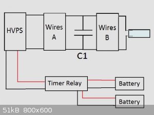
A summary of my tests:
- MOC (1uF) + 4m Wire B: 15/15. worked every time with 15 tested.
- Film capacitor bank (0.1uF rated 2500V) + 2m Wire B: worked, however only one test was made.
Also, I made some detonators differently so that the spark occurs a few millimeters above the ETN. All these tests failed. The spark occured but the
ETN did not detonate.
It is important that the discharge happens through the ETN crystals, not around it.
Despite the capacitors were only rated 2kV they were able to withstand the 5kV without problem.
Steve, from HV labs, tested MOCs to take up to 10kV before failing.
Be aware that the HV side of the circuit must the very well insulated. Any bare wire or connecting touching the earth, ground, and the current will
dissipate away and the capacitor wont charge enough.
I used those screw connectors made of plastic, common for mains power installations.
If you want to use the microwave oven capacitor make sure you open it up and remove the internal bleeder resistor, otherwise the voltage will not rise
enough to trigger a spark.
Always remember to discharge the capacitor after each run, bang or no bang, before you touch the HV side. And yes, touching just one
pole will shock your hearth out.
##########################################
About the HV Module.
They'r super fun and super scary to play with. Cheap and very easy to use. They consume 2Amps and will pull a 6V battery back down to 3.5V. Do keep an
eye on battery level as it drains quickly.
Capacitor charging time was about some 15 seconds for 1uF and under 2 sec for the 0.1uF bank.
Ebay Link
About the Timer Relay.
Cheap, easy and very usefull. There are various makers and models. This one I bought has 13 functions, one of which allows me to set T1, from turn on
to closing the relay and activating the HV module, stay on for T2 and then turn off the relay
Buy the 5 volt version as 12 volts is too much to ask from say a 9V battery. The battery will drain quickly and a 12V relay wont work with just 7V or
so. Better to have a 9V battery powering a 5V device.
Also use 2 batteries, one for the timer and another for the HV module.
Ebay Link
I'm quite sure that it is the spark discharge that initiates the ETN.
I do not yet know, however, how this happens exactly. High pressure, high temperature, shock wave, maybe a direct electrostatic phenomena?
I tried using no capacitor at all (only the small output capacitors from the HV module) and it did not work.
I do not know the limits of the system.
How small can the capacitor be and how long the wire B?
I find this system much simpler than an EBW and I now use it as a main explosive igniter.
My top so far was testing 0.4kg of ANFO boosted with 10g of ETN at the beach.
First time doing it. Proved to be way too much. The explosion was heard over 2km away, the ground trembled, a cloud of atomized sand persisted on the
site for an hour. The Seagulls bailed and didn't come back to this day. Some guy heard it and called the coast guard. They came, looked around and
left. Intense.
Cant way to do it again. 
There is allot to develop here. Unfortunately my summer vacations are over and I must go back to college.
I hope some of you will find this worthwhile to look into and continue to engineer this idea.
Looking forward for feedback!
Cheers.
|
|
|
Bert
Super Administrator
        
Posts: 2821
Registered: 12-3-2004
Member Is Offline
Mood: " I think we are all going to die. I think that love is an illusion. We are flawed, my darling".
|
|
I assume you used Copper wire for both the firing leads and the spark gap? What wire gauge/circular mils? What insulation type & Volt rating-
http://www.engineeringtoolbox.com/awg-wire-gauge-circular-mi...
Rapopart’s Rules for critical commentary:
1. Attempt to re-express your target’s position so clearly, vividly and fairly that your target says: “Thanks, I wish I’d thought of putting it
that way.”
2. List any points of agreement (especially if they are not matters of general or widespread agreement).
3. Mention anything you have learned from your target.
4. Only then are you permitted to say so much as a word of rebuttal or criticism.
Anatol Rapoport was a Russian-born American mathematical psychologist (1911-2007).
|
|
|
Aurium
Harmless

Posts: 46
Registered: 4-10-2015
Member Is Offline
Mood: Energetic
|
|
Thanks Bert, I forgot to mention the cables.
For the running cables, Wires A & B, I used speaker cable of about 17 AWG (1mm) dia. or so, I do not remember the exact gauge.
I found these cables to have no problem propagating the High Voltage, surprisingly.
The speaker wire cables come as if glued to each other, two wires in one strand, I kept them like this because two close parallel wires, with opposite
currents, will show less self-inductance than the same two wires at a distance from each other.
These cables were made of an copper and aluminum alloy.
For the spark gap leads I used that thin, single strand electronics jumper wires (forgive my english).
Like these, about 22 AWG.
Jumper wire
This is essentially a RLC circuit (capacitor, running cables, spark gap), and my goal is to maximize the power pulse to the spark gap.
Now, on my opinion, the resistance component of the circuit is very very low and negligible.
The plasma formed by the spark gap is indeed very conductive, film capacitors have low ERS, and the cables resistance is very low, certainly not the
current limiting factor.
I believe that it is the cable's inductance, Wires B, from the capacitor to the spark gap, that limits the current.
As a general approximation the cables used have about 300nH per meter.
A quick simulation on LTspice will show the importance of cable length on maximum power.
The same applies for an EBW.
Also I forgot to mention,
each of these detonators were filled with about 0.1g of ETN,
quite a loud bang, and enough to shatter plastic and dent metal.
And I did make another test,
1uF MOC + 15m Wire B, worked. Only one test.
[Edited on 5-10-2015 by Aurium]
|
|
|
careysub
International Hazard
    
Posts: 1339
Registered: 4-8-2014
Location: Coastal Sage Scrub Biome
Member Is Offline
Mood: Lowest quantum state
|
|
Quote: Originally posted by Aurium  | SGD
I came across the idea of detonating ETN with a EBW detonator (Exploding Bridge Wire), I decided to give a try to the concept after failing to ignite
my ETN with simple resistive pyro igniters.
Reading around the web and the forum on the look for a theory about the mechanism of an EBW, I developed my own theory, that the thin wire itself was
not the igniting mechanism, but instead it was the very hot and very conductive plasma gap created after the wire vaporizes that triggers the
explosive.
|
First off, I am unsure why you titled your post "spark gap detonator" when you do not discuss spark gap detonators at all (an EBW is not a spark gap
detonator which is a different beast).
The principles of EBW operation are very well understood, and you are correct in thinking that the post wire explosion plasma is important in a good
design.
Look at the current trace in this article:
http://iopscience.iop.org/article/10.1088/1742-6596/500/19/1...
You will see that the current dips as the wire vaporizes then rises again as the plasma bridge becomes established, achieving a new high in the
explosion energy.
I saw on-line earlier this year a nifty engineering handbook about exploding bridgewire detanators that set forth the established design pattern used
commercially (it has gotten dialed in to a very standard configuration for the firing set). It also discussed all aspects of its principles of
operation. Unfortunately in Googling I cannot now locate it. But perhaps someone else can find it again (I will keep trying).
|
|
|
Aurium
Harmless

Posts: 46
Registered: 4-10-2015
Member Is Offline
Mood: Energetic
|
|
Exactly. The plasma channel formed after the wire vaporizes is crucial for an EBW.
In my design however there is no thin wire at all connecting the two leads. Instead, the capacitor charges to a voltage high enough for a discharge to
jump across the leads. Hence the plasma channel is immediately formed and current rushes through it. A spark gap.
No energy is wasted vaporizing a thin wire, which allows for smaller capacitors. (Best so far was 0.1uF)
Nice article btw.
[Edited on 6-10-2015 by Aurium]
[Edited on 6-10-2015 by Aurium]
[Edited on 6-10-2015 by Aurium]
|
|
|
careysub
International Hazard
    
Posts: 1339
Registered: 4-8-2014
Location: Coastal Sage Scrub Biome
Member Is Offline
Mood: Lowest quantum state
|
|
Quote: Originally posted by Aurium  | Exactly. The plasma channel formed after the wire vaporizes is crucial for an EBW.
In my design however there is no thin wire at all connecting the two leads. Instead, the capacitor charges to a voltage high enough for a discharge to
jump across the leads. Hence the plasma channel is immediately formed and current rushes through it. A spark gap.
No energy is wasted vaporizing a thin wire, which allows for smaller capacitors. (Best so far was 0.1uF) |
My bad.
I did not read your design carefully enough - I thought the unifilliar wire was used as a bridge.
|
|
|
roXefeller
Hazard to Others
  
Posts: 463
Registered: 9-9-2013
Location: 13 Colonies
Member Is Offline
Mood: 220 221 whatever it takes
|
|
Excellent post. If only all first timer threads looked this well documented (mine wasn't). Have you given much thought to what other materials you
could try?
|
|
|
Aurium
Harmless

Posts: 46
Registered: 4-10-2015
Member Is Offline
Mood: Energetic
|
|
Thanks rox. Coming from a physics backgroud I can say I can write science  . .
I invented this detonator out of necessity so I could ignite more difficult explosives like rdx tnt anfo etc, without having to use dangerous
peroxides since I really don't have the chemicals to make safer primaries.
Out the back of my head I can imagine about trying this detonator filled with TNT or even RDX or an AN mixture. Who knows.
So I'll have 2 more days in the lab to make more experiments, from tomorrow. I don't have time to make rdx or tnt but I might try an AN mix. I should
try to get it as sensitive as possible first. What do you recommend?
For that big one I made I used 5% Mg powder and 5% methanol but maybe there's something better than that.
|
|
|
Bert
Super Administrator
        
Posts: 2821
Registered: 12-3-2004
Member Is Offline
Mood: " I think we are all going to die. I think that love is an illusion. We are flawed, my darling".
|
|
| Quote: |
For that big one I made I used 5% Mg powder and 5% methanol but maybe there's something better than that.
|
To what does "that big one" refer?
I would not store pure, uncoated Mg powder in contact with ANY oxidizer, it may very well self ignite- Especially with a hygroscopic, reactive
oxidizer such as ammonium nitrate.
In pyrotechnics, Mg powder is sometimes coated with boiled linseed oil and allowed to dry in a wide, flat, paper lined tray with frequent stirring.
The coating with polymerized oil is sufficient protection for some storage life with Potassium perchlorate, Barium or Strontium nitrates, but is
deemed insufficient for use with ammonium perchlorate.z
For use with ammonium perchlorate, Mg or Mg/Al alloy metal powders may be coated with dichromate as protection instead. See Takeo Shimizu, Fireworks:
The Art, Science and Technique for details.
http://www.scribd.com/mobile/doc/14654551/Fireworks-the-Art-...
Ammonium nitrate:Aluminum at about 90:10 is about as sensitive as is safely achieved without such things as the HE's you say you don't have time for-
But the critical diameter is MUCH larger than your low density PETN.
Rapopart’s Rules for critical commentary:
1. Attempt to re-express your target’s position so clearly, vividly and fairly that your target says: “Thanks, I wish I’d thought of putting it
that way.”
2. List any points of agreement (especially if they are not matters of general or widespread agreement).
3. Mention anything you have learned from your target.
4. Only then are you permitted to say so much as a word of rebuttal or criticism.
Anatol Rapoport was a Russian-born American mathematical psychologist (1911-2007).
|
|
|
Laboratory of Liptakov
International Hazard
    
Posts: 1415
Registered: 2-9-2014
Location: Technion Haifa
Member Is Offline
Mood: old jew
|
|
NPED
Quote: Originally posted by Aurium  |
I invented this detonator out of necessity so I could ignite more difficult explosives like rdx tnt anfo etc, without having to use dangerous
peroxides since I really don't have the chemicals to make safer primaries.
Out the back of my head I can imagine about trying this detonator filled with TNT or even RDX or an AN mixture. |
A nice piece of work. I mean no fun. Really good work. High voltage, ETN, everything is nice. But if need detonator without primary substance is this:
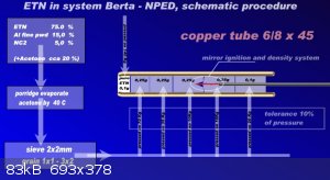
Or another suggestion: Use the same substance in a slim package. Without pressing. According to the scheme: ETN 75, aluminum 15, and nitrocellulose
(12,4N) 5%. The results will be even better. Lower voltage will suffice. In this system, is voltage 6V/1A, thus classic power supply.
Dr. Liptakov
|
|
|
Aurium
Harmless

Posts: 46
Registered: 4-10-2015
Member Is Offline
Mood: Energetic
|
|
Bert:
| Quote: |
To what does "that big one" refer?
|
I was referring to the 400g AN mixture I detonated at the beach a week ago. I write about near the end of my original post. But yes I guess "big" is
relative  . .
I had no idea Mg powder could react cold with AN. At the time I used it because I didn't have Al powder. I'll be sure to buy some Al powder and use
that instead, next time.
The article you posted is interesting and will sure be useful in the future.
I used to make small skyrockets back in my early days, sadly only a few ever made it upwards.
Liptakov
Thanks! I really appreciate it!
That's exactly what I was trying to achieve at first, using inexpensive pyro igniters to get the ETN going. I did even use Al powder but I ultimately
failed.
But yea I'll have that formulation with NC when I have some time in the lab. Looks quite complex to make though  . .
I went back home for the weekend and I took some photos (nothing new).
Here you can see,
6V battery for HV module, 9V battery for timer, HV module, timer relay, 0.1uF capacitor bank, the speaker cables connecting everything and the
detonator.
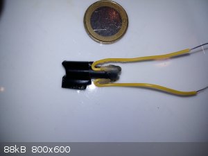 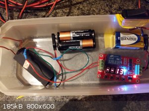 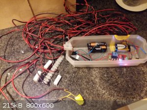 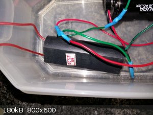 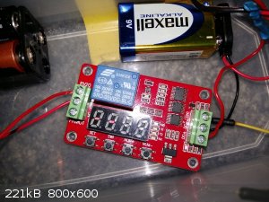
I also tested:
- 15m wire B, no capacitors at all (just the HV module's internal capacitor), Failed.
- 15m wire B, 0.1uF, Failed. It just popped and the ETN was shot out, even leaving the casing intact. Nothing like the full loud detonations I was
getting.
- 2m wire B, 0.1uF, OK. Again.
Any suggestions of more experiments with this setup? I have one more day at the lab.
|
|
|
Aurium
Harmless

Posts: 46
Registered: 4-10-2015
Member Is Offline
Mood: Energetic
|
|
Yea I'v been reading the thread about the NPED.
http://www.sciencemadness.org/talk/viewthread.php?tid=24817
I'd love to know more on your work on these NPED detonators Liptakov.
I doubt the SGD has any real value outside the world of hobbyists with whom I am happy to share my findings, but I'v read about pending patents in
that post, which boosts another level of interest.
Then again, a 0.1uF film capacitor rated a few kV would cost cents, and the HVPS is a few dollars, making the system sacrificial if there is no chance
to recover it. So... maybe?
EDITED
Nevermind. I found the patent for this idea and it dates back to the 1950's.
| Quote: |
Detonating apparatus
US 3955505 A
Link
|
It seems it was an idea for the detonators used in nuclear weapons but got replaced by EBW systems.
I was right on the money with the 0.1uF at 5kV eheh.
Anyways, despite not being novel, now these forums know about it.
[Edited on 10-10-2015 by Aurium]
|
|
|
roXefeller
Hazard to Others
  
Posts: 463
Registered: 9-9-2013
Location: 13 Colonies
Member Is Offline
Mood: 220 221 whatever it takes
|
|
With those firing wire lengths, you're just fighting physics. The common fixes are more potent discharges through the wire (reduced somewhat with
larger diameter wire), or local/sacrificial discharge capacitors that are charged/triggered through the firing wire. That's one of the benefits of
det cord, when your distance is too long for your wire diameter. Since you are avoiding primaries but are handy with equipment, maybe try a det cord
machine...
|
|
|
Bert
Super Administrator
        
Posts: 2821
Registered: 12-3-2004
Member Is Offline
Mood: " I think we are all going to die. I think that love is an illusion. We are flawed, my darling".
|
|
Set up the final output stage of electronics at a distance such that it is not guaranteed to be "sacrificial", then use an improvised signal cord to
transfer detonation to main charge?
http://www.sciencemadness.org/talk/viewthread.php?tid=33395
http://youtu.be/ZnMqOF28STM
Rapopart’s Rules for critical commentary:
1. Attempt to re-express your target’s position so clearly, vividly and fairly that your target says: “Thanks, I wish I’d thought of putting it
that way.”
2. List any points of agreement (especially if they are not matters of general or widespread agreement).
3. Mention anything you have learned from your target.
4. Only then are you permitted to say so much as a word of rebuttal or criticism.
Anatol Rapoport was a Russian-born American mathematical psychologist (1911-2007).
|
|
|
Laboratory of Liptakov
International Hazard
    
Posts: 1415
Registered: 2-9-2014
Location: Technion Haifa
Member Is Offline
Mood: old jew
|
|
ETN as non primary detonator
For Berta system is necessary to comply with these conditions: metal - 1 mm thick. Steel, or copper, 6 mm inner diameter. Initiation point
(resistance wire) if possible small size. This is seen in the video here: ....... https://www.youtube.com/watch?v=PZiQ9LCRzeg .....Further, it is necessary to keep the grain size. It is best to 2x2m. For quick burn. Like
gunpowder. Large clean grains, no fine dust. It is a general principle. For you, it is an important principle of performance. This is clearly visible
in the video. In the video used a different blend. After many tests it appeared that TeACP not needed. Only ETN75 -80, 15 -20 and aluminum NC 5 -10.
as a binder. Melting point of the mixture is not 60C, but 90C. When 90C (with 10% NC2) this mixture as a soft rubber. For this is a simple
explanation. Above 60C is ETN liquid, in other words, liquid nitro ester. Liquid nitro ester (or nitro compound) form mixed with NC gelatin. The
difference is that for the ETN / NC must work with an ambient temperature above 60C. But I digress from the issue. A detonator system Berta obviously
filled at room temperature. Important is that the internal grain structure is maintained at 60C. For example, in direct sunlight. The test results are
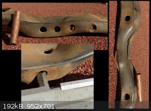
equally large holes in 2 mm steel plate, in diameter 7-8 mm.
In the video used mechanical pressing. This is not necessary. The output segment is clean ETN is pressed at 140 kg. It is not a condition. Suffice 70
kg. Furthermore, 70 kg, 35, 10 and so on according to the diagram. For these pressures sufficient scale to weigh people.
Dr. Liptakov
|
|
|
Metacelsus
International Hazard
    
Posts: 2539
Registered: 26-12-2012
Location: Boston, MA
Member Is Offline
Mood: Double, double, toil and trouble
|
|
For the problem of transmitting the electricity, you might need to take wavelike behavior into account for the longer wire lengths. Your voltage input
can be reasonably approximated by a step function. If 10 MHz is a rough estimate of the highest important frequency component (i.e, the capacitor
discharges in ~100 ns or less), then the wavelength will be around 30 m.
For two ideal wires 1 cm (rough estimate) apart (in air, dielectric constant 1) and 0.5 mm in radius, I calculate a characteristic impedance of 443
ohms, with an inductance of 148 pH/m and a capacitance of 0.7531 fF/m. The relevant thing here would be the step response of the transmission line.
But this is just an approximation. Do you have an oscilloscope that you can test with? (Obviously, don't put the explosives in when you do that.)
One other thing: It would be an interesting replacement for detcord to use the output of an explosively pumped flux compression generator to set off
more explosives.
|
|
|
Aurium
Harmless

Posts: 46
Registered: 4-10-2015
Member Is Offline
Mood: Energetic
|
|
Bert, Rox:
Sounds like a plan. I'v been trying to make detcord for a while but failed pathetically ahah. Next time available I might try again, following other
member's work. Looks like allot of fun.
To the tests I made at the beach I used 15m Wire A and 3m Wire B, I then enclosed the MOC in a Tupperware and buried in the sand close to the charge,
this was enough to protect it from 400g ANFO.
Liptakov:
I must say I really admire your commitment to the NPED! I wish I had came across your post earlier and I would have tried it this summer.
I wonder if it could be made to work with regular Visco fuse, reliably.
Cheese:
Indeed I did not consider any RF phenomena.
What I did was I first estimated the wires self-inductance using this app:
http://www.eeweb.com/toolbox/parallel-wire-inductance/
on Parallel Wires 1mm dia. 3mm distance, 100cm length and it farts 700nH/m.
Now I plug that into LTspice.
For a 1uF cap, 2meters of this wire, a 100mOhm resistor as a model for the spark gap, and I get an oscillating frequency of under 200kHz (5us). Very
different from the 10Mhz you estimate..
So how are you calculating wire inductance?
Nah I don't have an oscilloscope, but I do plan on getting one for myself next summer. I guess I can take it to college and ask my electronics teacher
to use the electronics lab. A tad suspicious eh. It should be fine though, people here don't panic over a clock  . .
Yeah I have my mind set on making a explosively pumped flux compression generator when I get the chance!
Explosives and High Voltage do ride together very well with interesting results  . .
|
|
|
Metacelsus
International Hazard
    
Posts: 2539
Registered: 26-12-2012
Location: Boston, MA
Member Is Offline
Mood: Double, double, toil and trouble
|
|
Quote: Originally posted by Aurium  | Parallel Wires 1mm dia. 3mm distance, 100cm length and it farts 700nH/m.
Now I plug that into LTspice.
For a 1uF cap, 2meters of this wire, a 100mOhm resistor as a model for the spark gap, and I get an oscillating frequency of under 200kHz (5us). Very
different from the 10Mhz you estimate..
So how are you calculating wire inductance?] |
First, I used different numbers (1 cm spacing), so I got different results for the inductance. For 3 mm spacing, I get 705 nH/m, which is close to
what you got.
The 10 MHz isn't a resonant frequency. Since the step function is not a sinusoid, it can be thought of as an infinite series of multiple different
frequencies (a Fourier transform, see https://en.wikipedia.org/wiki/Heaviside_step_function#Fourie...). What I was saying was that frequencies higher than 10 MHz probably aren't
important. I would have to know the precise characteristics of the capacitor (ESR, ESL, etc.) to give a precise analysis.
Also, I would model the spark gap as an open circuit. If the model gives a voltage greater than the breakdown voltage, then the device is reasonably
likely to work. However, if the problem you have is that the gap makes a spark, but not at high enough current, then modeling the spark gap as a
low-value resistive load makes sense.
[Edited on 10-10-2015 by Cheddite Cheese]
|
|
|
Bert
Super Administrator
        
Posts: 2821
Registered: 12-3-2004
Member Is Offline
Mood: " I think we are all going to die. I think that love is an illusion. We are flawed, my darling".
|
|
I do see some applications for this, not in demolition or quarry work, where the charges are large and the leads would need to be long- But for
special effects work in studios, miniatures & similar video work. The leads need not be long on a video set/green room, and I like the possibility
of tailoring small PETN charges for each specific application with no handling of primary explosives, no expensive commercial blasting caps and no
metal detonator caseings to fragment and potentially damage sets/equipment/crew.
Rapopart’s Rules for critical commentary:
1. Attempt to re-express your target’s position so clearly, vividly and fairly that your target says: “Thanks, I wish I’d thought of putting it
that way.”
2. List any points of agreement (especially if they are not matters of general or widespread agreement).
3. Mention anything you have learned from your target.
4. Only then are you permitted to say so much as a word of rebuttal or criticism.
Anatol Rapoport was a Russian-born American mathematical psychologist (1911-2007).
|
|
|
Aurium
Harmless

Posts: 46
Registered: 4-10-2015
Member Is Offline
Mood: Energetic
|
|
Bert
I'd though about special effects as well Bert. Yea these detonators can be made very very small. So far I'v used only 0.1g but one would guess it can
be made to work just as well with even just 10mg or so.
The smaller capacitors and low charging current = thinner or even invisible wires or smaller batteries, and it shouldn't be hard to make a radio or IR
controlled SGD.
Sadly, there isn't much of a movie industry here but I can try to ask around people connected to theater maybe to see I can pick up an interest.
Cheese
Now it makes sense.
You had mention 148 pH/m on your previous post, an order of magnitude less than my estimate. Maybe a typo or bad conversion to meters?
Still, I can't figure why it is of your belief that we have a step function here.
I use this model:
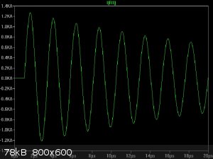 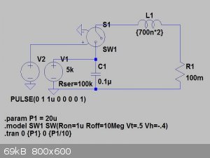
V1 charges the cap to the 5kV, then V2 goes high, which causes SW1 to connect. Like a spark gap, no current when no arc, ~100mOhm resistance when the
arc is formed.
But then again I really have no idea what value to use for the spark gap resistance.
|
|
|
Grantr
Hazard to Self
 
Posts: 57
Registered: 19-9-2015
Member Is Offline
Mood: No Mood
|
|
Aurium,
Thanks for giving me the link to your setup. Is the purpose of the timer so you can set it and get away before the charging begins? I am thinking of
using a radio remote control to fire my unit. I already have plenty of R/C airplane electronics.
How wide is the spark gap? It looks like it is just under 3mm by the drawing. The patent you referenced had a spark gap of less than 1mm and the HE
pressed to 100lbs of force. Your unit fires it self when the voltage is high enough correct?
Are you using any diodes to protect the HV supply?
|
|
|
Aurium
Harmless

Posts: 46
Registered: 4-10-2015
Member Is Offline
Mood: Energetic
|
|
No problem. Thanks for bringing it up.
Yea the timer is really simple to use, when the relay closes it activates the HV module which starts charging the capacitors, once the capacitor
voltage is high enough a discharge forms inside the detonator and caboom.
I used around 3 or 4mm spacing I don't think it matters too much. The firing voltage will change of course. I have to try with smaller gaps, see if I
can reduce the voltage required.
Like I said, I didn't compress my ETN at all, just pushed it in, low density.
And I didn't use diodes. These HV modules are surprisingly tough.
But hey report back if you use the airplane RC system! Sounds like a great idea if you can get good range.
Do mind safety, people have died due to false RF signals when setting up the charge. Then again this is up to you.
|
|
|
Grantr
Hazard to Self
 
Posts: 57
Registered: 19-9-2015
Member Is Offline
Mood: No Mood
|
|
Aurium,
I plan to use at least an 8 meter B line. I may use a rg6 coaxial for this and then use speaker and or lead wire for the spark gap.
I will use a servo to activate a push button switch to turn on the Hv supply.
2.4 ghz radio systems are resistant to false RF signals. Unlike the old 72mhz systems than used crystals and were prone to glitches from RF
interference from sparkplugs and other random RF interference.
|
|
|
Grantr
Hazard to Self
 
Posts: 57
Registered: 19-9-2015
Member Is Offline
Mood: No Mood
|
|
I just ordered this HV Power supply and four of these HV film Caps. I should get this in a few days i hope. I also have a .7uf 2100 volt MOC that I can add to these caps to have 7300 volts. I plan to
just use the 4 caps in series.
This should make a strong spark. A bit overkill I suppose.
|
|
|
Hennig Brand
International Hazard
    
Posts: 1284
Registered: 7-6-2009
Member Is Offline
Mood: No Mood
|
|
Found an interesting page with information on this topic:
http://nuclear-knowledge.com/detonators.php
I bolded the section on spark-gap detonators.
"
Detonators
Detonators are used to initiate explosives where it is necessary to create a shockwave.
Creating a symmetric implosion shockwave for a nuclear weapon needs close
synchronization when the detonators are fired. The tolerance for timing differences is very
low: of the order of 100 nanoseconds is necessary.
With a conventional detonator, a wire is electrically heated. This causes a small quantity of a
sensitive primary explosive to detonate (for example lead azide, mercury fulminate etc). The
primary explosive then initiates a secondary explosive (for example PETN or tetryl), which
then fires the main high explosive charge.
This process of electrically heating the wire, and then heat conduction to the primary
explosive until it reaches detonation temperature, needs several milliseconds - and there
may be large timing errors. This means that conventional detonators do not have the
necessary timing exactness to fire an implosion system in a nuclear weapon.
Exploding Bridgewire Detonators (EBW)
Nuclear weapon implosion systems need nanosecond accuracy for firing the detonators and
exploding bridgewire (EBW) detonators are often used. One method to reduce the duration
of action of the detonator is to send a sudden powerful surge of electric current through a
very thin wire of gold or platinum in a specially designed detonator. The current heats the
wire until the point of vaporization. This specially designed EBW technique was invented by
Luis Alvarez at Los Alamos during the Manhattan Project.
Current surge rise times of a fraction of a microsecond are possible, and a spread in
detonation times can be several nanoseconds. This is sufficiently exact for very low
tolerance applications such as firing explosive lenses in nuclear weapons.
EBW detonator
It is possible to employ an exploding bridgewire detonator to initiate a primary explosive
which is usually lead azide exactly like in a conventional detonator. However, if the surge of
electrical current is sufficiently powerful, the exploding bridgewire can directly initiate a less
sensitive booster explosive like PETN. One advantage of this method is that there is much
less risk of accidental activation by heat, stray currents, or static electricity than for a
conventional detonator. Very fast and powerful surges of electrical current are necessary to
fire the detonators and initiate a less sensitive explosive though. This type of exploding
bridgewire detonator is one of the safest types of detonators known to scientists.
The disadvantage is that a typical EBW needs very fast and powerful surges of 5,000 volts,
with a peak current which consists of at least 500-1000 amps. Several kiloamps is more
typical for most EBW detonators, however a multi-EBW system would probably try to
minimize the current needed. It is possible to get timing accuracies which are better than 10
nanoseconds with sufficient attention in detonator design and construction. EBWs were
used in the American Trinity "Gadget" device. The EBW and the slapper detonator are the
safest known types of detonator.
Slapper Detonators
There are a number of more recent detonator designs which are based on exploding foils
which have been developed. Exploding foil detonators use a different design concept from
EBWs: this is called a slapper detonator. This is also sometimes called an exploding foil
initiator (EFI).
This idea was developed in America and elsewhere in the world. It uses the expanding foil
plasma to drive another thin foil or plastic film "flyer" to high velocity across a gap, which
initiates the explosive by means of impacting the surface at high velocity.
Slapper detonators are quite efficient for the conversion of electrical energy into kinetic
energy in the flyer. It can be possible to achieve 25-30% energy transfer. This delivers the
energy needed to initiate a detonation of the explosive.
A typical slapper detonator consists of an explosive pellet which is pressed to a high density
in order to gain maximum strength. It is also possible to use polymer bonded explosives for
this. There is an insulation disk which has a hole in the center next to the explosive pellet
and the hole is set against the explosive pellet. An insulating flyer film (for example Kapton
or Mylar) with a metal foil etched to one side is placed against the disk. A narrowed section
of the etched foil serves as the bridgewire.
The large current firing pulse causes the narrowed section of the foil to become vaporized.
Then this breaks the insulated flyer which accelerates down the barrel of the disk and
impacts the explosive pellet. As a result this impact transmits a shock wave into the
explosive which causes it to detonate.
A slapper detonator has the advantage of the ability to initiate an area of the explosive
surface rather than a singular point. It is possible that this will make the design of compact
implosion systems easier.
This system has several advantages in comparison with the EBW detonator:
•The metal bridge becomes completely separated from the explosive by means of an
insulating film and an air gap (the bridgewire of an EBW detonator is in direct contact
with the explosive)
•It is possible to pack the explosive to a very high density
•The amount of energy which is needed to fire the detonator is less
•Very insensitive explosives can be detonated - this is extremely difficult with regard
to an EBW detonator
Typically the detonator bridgewire which is used in EBWs consists of highly pure gold or
platinum, is 20-50 microns wide and about 1 mm long. PETN is normally used as the
explosive, possibly with a tetryl booster charge. Slapper detonators use metal foils (usually
aluminum, but gold foil would work well also) which are put on a thin plastic film (this is
usually Kapton). A wider variety of primary explosives can be used. PETN or HMX may have
been used in slappers in earlier weapon systems, but weapons using insensitive high
explosives probably use the explosive HNS which is very stable to heat.
Spark-Gap Detonators
The spark-gap detonator is another type of very fast detonator. It employs a high voltage
(approximately 5,000 V) spark which is created across a narrow gap to initiate a primary
explosive. Using a very sensitive primary explosive (like lead azide or lead styphnate) the
amount of current necessary is relatively small; a small-sized capacitor can supply enough
power.
The main disadvantage for this type of detonator design is that it is quite unsafe. Static
charges or other induced currents can very easily fire a spark gap detonator by accident. For
this reason it is unlikely that they have been used in deployed nuclear weapons.
Spark-gap detonators use primary explosives like a normal (non-fast-acting) detonator. A
normal detonator uses a metal filament in contact with primary explosive. An electric
current heats the metal filament until it gets extremely hot (red) and heat transfers to the
near primary explosive by conduction. The explosive then detonates.
However, a spark-gap detonator has two electrodes with a gap between them, which is filled
with primary explosive. An electric spark is passed across this gap and this spark detonates
the explosive. It is extremely fast-acting and gives high timing exactness with a multi-
detonator system because it is not necessary to rely on thermal conduction of heat to
initiate the explosive.
Because primary explosives are used, it is not necessary for the spark to be particularly high
energy. Primary explosives can be detonated easily from a low energy input.
These types of detonators are used in the Russian RPG-7 HEAT ammunition. The
ammunition has a nose mounted piezoelectric part. When it strikes something hard it gives a
pulse of electricity. They are ideal for this type of application, because the ammunition is
needed to function immediately when it strikes the target.
Scientists examined the use of spark-gap detonators in the Manhattan Project and the Indian
Nuclear program, but they were replaced by EBWs, as a result of safety questions.
Power Sources
For these types of detonators special power sources are necessary to produce the large
current surges which are needed.
For a nuclear weapon, a quite compact and light high-speed pulse power supply is
necessary for the detonation system. A power source which is very powerful and able to discharge
extremely quickly is necessary to achieve accurate timing and a fast response. Fast, accurate
and reliable switching components are also needed, and it is also necessary to manage the
inductance of the whole system.
The usual method for providing the power for an EBW multi-detonator system is through the
discharge of a high capacitance, high voltage, low inductance capacitor through a suitable
switch and into the bridgewire. The voltage range which is necessary is on the order of
several kilovolts (5 KV is normal). Silicone oil filled capacitors with the use of Kraft paper,
polypropylene, or Mylar dielectrics are suitable, ceramic-type capacitors are also. Compact
power supplies for charging capacitors are easy to acquire.
The capacitor also needs a switch which can handle high voltages and currents. The switch
must also be able to transition from a safe, non-conducting state to a fully conducting state
very rapidly, and without adding unnecessary inductance to the circuit.
A variety of switch technologies is available: triggered spark gaps, krytrons, sprytrons,
thyratrons and explosive switches are some which can be used.
KN2 Kryton switch tube
Triggered spark gaps are sealed devices which are filled with high pressure air, argon, or SF6.
A non-conducting gap between electrodes becomes closed by means of applying a triggering
potential to a wire or grid in the gap. Typically, compact versions of these devices rate at 20-
100 KV, and 50-150 kiloamps, and the triggering potential is one-half to one-third the
maximum voltage. Switch current rise times last 10-100 nanoseconds.
Krytrons are a type of cold-cathode trigger discharge tubes which are filled with gas. The gas
is normally hydrogen, although it is possible to use krypton. Some of these contain a small
amount of Ni-63, which is a weak beta emitter which keeps the gas in a slightly ionized state.
Applying a trigger voltage causes an ionization cascade to close the switch. They are used as
an extremely high speed switch. These devices have maximum voltage ratings from 3 to 10
KV, and peak current rating of 300-3000 amps. This makes them unsuitable for directly firing
multiple EBW detonators. Krytrons are employed commercially in powerful xenon flash lamp
systems, and have other uses. They have faster response times than other types of trigger
discharge tubes.
The vacuum variant is called a vacuum krytron or sprytron. It is very similar and has a very
high radiation resistance. Sprytrons have faster switching times than krytrons. It is probably
the sprytron that is used in nuclear weapons.
Detonators in nuclear weapons are normally wired in parallel for reliability and to reduce
inductance. In the American "Fat Man" atomic bomb scientists wired the detonators in
parallel in triggered spark-gap circuits. There were four detonating circuits. Any two of these
circuits provided enough power for all 32 detonators. Each detonator was wired to two
different circuits in order that a failure of any one detonator circuit would not affect the
implosion. The whole system was fired by a spark-gap cascade. The triggered spark-gap
supplied a current surge to fire the four main circuits at the same time."
"A risk-free world is a very dull world, one from which we are apt to learn little of consequence." -Geerat Vermeij
|
|
|
| Pages:
1
2
3 |
|