| Pages:
1
..
5
6
7
8
9
..
11 |
Gargamel
Hazard to Others
  
Posts: 166
Registered: 9-3-2013
Member Is Offline
Mood: No Mood
|
|
| Quote: |
5 milliohms of ESR |
Rather 20 or more, most caps simply don't have the voltage rating needed, so one has to put several in series.
And capacitors with higher voltage rating than 1xxxV are much more expensive.
My feeling is that a lot of small capacitors with high voltage in parallel is better than a lot of big capacitors in series. But the price...
Did you ever think about some kind of regulation?
My worry would be that due to some uncertain factor like a battery a little stronger ect. the output voltage gets to high, destroying the expensive
capacitors.
edit:
concerning typical coax cables:
Any experience about how the behave after some rough handling "in the field"? Most of these are meant to be placed somewhere permanently, like in a
satellite TV installation ect. and not moved around hundreds of times.
edit2:
How about these paper/oil capacitors, like this one here:
http://www.ebay.co.uk/itm/HUGE-Russian-K41-1a-Paper-PIO-capa...
I've never found any ESR/ESR informations about these types...
Any idea how good they are compared to MKP or FKP types?
[Edited on 11-7-2015 by Gargamel]
[Edited on 11-7-2015 by Gargamel]
|
|
|
Hennig Brand
International Hazard
    
Posts: 1284
Registered: 7-6-2009
Member Is Offline
Mood: No Mood
|
|
I would spent a little money and get suitable capacitors with suitable voltage, ESR, ESL and current ratings. We are limited somewhat by capacitor
availability and price I guess. It is obviously much better to put the capacitors in parallel as much as possible, but we make do as best we can with
what is available. These are not single use items either and should be good for thousands of shots if not abused (I think). The capacitors I bought,
which Nuxy linked to a little earlier, are 2000V and 0.15uF with 5mohms of ESR, so for a 0.6uF bank made up of 16 (8 parallel strings of 2 in series)
the ESR would be about 1.25mohms (unless I messed up somewhere). The 16 capacitors I bought cost me about $130 Canadian (including delivery), so yeah
they are expensive but keep in mind there are cheaper albeit often less durable options available. I bought the type I did because they are greatly
favored by the Tesla coil enthusiasts and are supposed to be incredibly tough.
The big thing is to monitor capacitor voltage when charging and stay under the rated voltage for maximum life, probably even as much as 20% under for
best longevity and prevention of overcharging accidents would be wise. Yeah, some type of overcharge prevention circuitry could be employed. I was
thinking of using an op-amp used as a comparator to monitor the charge voltage via the voltage multiplier. A small circuit could be used to send small
pulses to simply maintain the level of charge once the capacitor was charged to the desired set point.
I have found RG-6 to be incredibly tough, at least so far. Why would anyone need to be excessively rough with the cable? I am careful not to pinch or
put hard bends or kinks in the cable, but other than that the cable doesn't seem to require any special treatment.
That capacitor you linked to would likely be better suited to starting or stopping someone's heart than a practical EBW system. It is a very scary
capacitor at 4000V and 160J !
[Edited on 12-7-2015 by Hennig Brand]
"A risk-free world is a very dull world, one from which we are apt to learn little of consequence." -Geerat Vermeij
|
|
|
Gargamel
Hazard to Others
  
Posts: 166
Registered: 9-3-2013
Member Is Offline
Mood: No Mood
|
|
I'm ignoring the inductance here, but imagining a setup with 2 strings a 5 of the 5µ/1300V caps would give 12,5mOhm for 2µF -> a time constant of
25ns. So the capacitors alone should have finished the bulk of their business in that time, if the rest of the circuit lets them.
The RG213 Cable has about 300mOhm DC Resistance, back and forth for 100feet. Even with shorter cables much more than the caps.
| Quote: |
The capacitors I bought, which Nuxy linked to a little earlier, are 2000V and 0.15uF with 5mohms of ESR, so for a 0.6uF bank made up of 16 (8 parallel
strings of 2 in series) the ESR would be about 1.25mohms (unless I messed up somewhere) |
One question:
My feeling is that it's easier the transmit the energy through a higher voltage. Why didn't you choose something like 3 in series and 5 strings
parallel?
After all the cable is the bottleneck...? Only to have a little less strain on the caps?
And also wonder:
These dV per time ans peak ampere reatios - arent't these rather ment for continous operations? Like every cycle of a switching PSU ect.
We only do single cycles every once in a while. As long as nothing is damaged in this few hundred µs it can cool down literally forever...?
-> so it's even pointless, to some extent...?
-> why not rather use 6000V or even 8000V? I would also assume the switch to be easier to set up at higher voltage.
| Quote: |
I have found RG-6 to be incredibly tough, at least so far. Why would anyone need to be excessively rough with the cable? I am careful not to pinch or
put hard bends or kinks in the cable, but other than that the cable doesn't seem to require any special treatment. |
The DVB-C Cables I know are some kind of stiff... I don't know, just some thought. The central conductor is not a flexible strand, but rather a rod.
If you roll this out hundreds of time I would assume it to break some time.
Since 1 M
| Quote: |
That capacitor you linked to would likely be better suited to starting or stopping someone's heart than a practical EBW system. It is a very scary
capacitor at 4000V and 160J ! |
I mentioned it as an example for the type. The large capacity of this one is overkill for our needs of course.
[Edited on 12-7-2015 by Gargamel]
|
|
|
markx
National Hazard
   
Posts: 649
Registered: 7-8-2003
Location: Northern kingdom
Member Is Offline
Mood: Very Jolly
|
|
The K-41 type are an ancient soviet oil/paper design....usually the smaller ones could be found in the phase shifting circuits of asynchronous
electric motors. A rather mediocre type of caps. I would be quite surprised if they held up to the ESR ESL standards of contemporary designs.
The one in the ebay picture is a deathtrap if stored like that...with unshorted leads that is. These huge bastards tend to gather charge all by
themselves if left in storage in an unshorted condition and can give you a really nasty surprise if you do not know the danger.
I still remember the hit a 720pF hv cap gave me when I was constructing a TIG welder arcstarter years ago. It's not an experience I intend to repeat

Exact science is a figment of imagination.......
|
|
|
nux vomica
Hazard to Others
  
Posts: 267
Registered: 18-7-2013
Member Is Offline
Mood: No Mood
|
|
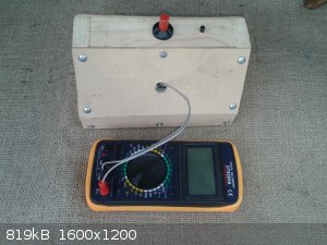
You dont want to be lugging around anything that is too big as well here is my setup in a temporary box .
|
|
|
dangerous amateur
Hazard to Others
  
Posts: 148
Registered: 8-7-2011
Member Is Offline
Mood: No Mood
|
|
Interesting stuff!
Say what kind of metal do you use on your spark gap switches? Bronze?
They must withstand enormous currents, wont they burn down after relativly few shots?
Won't the plastic tube surrounding the electrodes burn away too?
I'd also be afraid the HV finds a way into the piezo switch, and into the finger operating it 
[Edited on 13-7-2015 by dangerous amateur]
|
|
|
Hennig Brand
International Hazard
    
Posts: 1284
Registered: 7-6-2009
Member Is Offline
Mood: No Mood
|
|
Nice compact looking fireset you have there!
Since the trigger pulse is very low current and high voltage some resistance can be placed between the trigger electrode and the trigger pulse
generator without reducing the effectiveness of the trigger pulse significantly. I have about 150 ohms between the pulse transformer and the trigger
electrode IIRC, which helps ensure that the firing line and bridgewire present a much lower impedance load for the main discharge across the switch
(provides isolation). I think he is probably alright with the piezo igniter, but it doesn't hurt to be careful. An extra rubber insulator or cover
could be put on or over the piezo igniter button if more insulation/isolation between finger and high voltage switch was needed.
Quote: Originally posted by Gargamel  |
One question:
My feeling is that it's easier the transmit the energy through a higher voltage. Why didn't you choose something like 3 in series and 5 strings
parallel?
After all the cable is the bottleneck...? Only to have a little less strain on the caps?
|
Yes, higher voltage results in higher di/dt, but why is that necessarily better? My system already works great even through over 100ft of RG-6 when
charged to 3800V. It will cost more for capacitors to get the same amount of capacitance at higher voltage and the capacitor bank will be much
bulkier. The danger of and from an accidental shock will be greater. It will put more strain on the capacitors; the current through a series string of
capacitors is the same, while parallel strings share the current between them. As voltage increases all system components generally get bigger and
bulkier and more expensive. Once the system works well and is reliable, why increase the voltage, system size, expense and danger? There are some good
reasons why the commercial systems are normally 3000-4000V, and I am sure I have not thought of all of them.
[Edited on 13-7-2015 by Hennig Brand]
"A risk-free world is a very dull world, one from which we are apt to learn little of consequence." -Geerat Vermeij
|
|
|
dangerous amateur
Hazard to Others
  
Posts: 148
Registered: 8-7-2011
Member Is Offline
Mood: No Mood
|
|
Can somebody please write an opinion about my trigatron question?
Quote: Originally posted by Hennig Brand  | I spent the last few hours making a smaller trigatron. The tubing used is food grade vinyl I believe (it was part of a wine/beer brewing kit) and is
an excellent insulator. Not exactly sure how well the tubing is going to respond to high voltage discharges, but it should be fine I think especially
since it is only one discharge every now and then, not constant repetitive discharges. The tubing fits the electrodes like a glove, in fact it is a
little difficult to get them apart once together. Half inch brass rod was used as the starting point. Here are a few pictures.
|
How did this brass and the insulation survive the firing?
Did you experience erosion and how severe was it?
Do the electrodes have to be re-adjusted very often?
And will not the rapid expanding hot air around the plasma rip away the insulation hose?
I used to "play" with HV a few years ago and i built a trigatron simply with 3 Nails and a bugzapper. But that was before my interest in energetics...
I never had such high currents.
[Edited on 13-7-2015 by dangerous amateur]
|
|
|
Hennig Brand
International Hazard
    
Posts: 1284
Registered: 7-6-2009
Member Is Offline
Mood: No Mood
|
|
Sorry about that, I noticed your post earlier and then got side tracked by something else.
The brass should stand up quite well. Brass electrodes are commonly used by the Tesla coil enthusiasts which is a much higher demand application with
repetitive discharges whereas an EBW switch is only fired once per explosive blast normally. I have only fired my trigatron about 15-20 times now, but
I did just check and there doesn't appear to be any noticeable damage to the electrodes. The electrodes, if not too small and easily damaged,
shouldn't need adjustment very often in my opinion. I haven't used the trigatron in the plastic hose yet, but I think it will be fine. It is a very
rapid discharge and the resistance of the spark gap drops to quite a low value which should keep heat dissipation to a minimum (I don't know for sure
though). The thing I was worried about was arc over across the plastic tubing, which would simply mean that the switch capsule would need to be made
bigger, or change its shape or change material of construction, etc. Efficient spark gap switch electrodes are of a large enough size and are shaped
properly. The Tesla coil people normally use spherical or hemispherical electrodes (e.g. rounded end on a rod electrode).
BTW, a bug zapper is the heart of my trigger pulse generator at the moment too.
"A risk-free world is a very dull world, one from which we are apt to learn little of consequence." -Geerat Vermeij
|
|
|
nux vomica
Hazard to Others
  
Posts: 267
Registered: 18-7-2013
Member Is Offline
Mood: No Mood
|
|
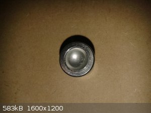
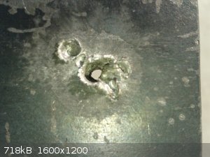
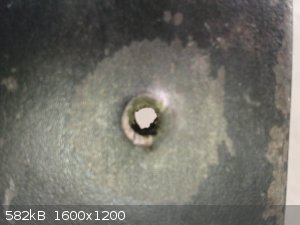
Thought I'd try something different today by useing 0.55 mm stainless steel as the liner, exactly same size as my copper one's in the rivnut setup ,
1.2 grm + 0.1 etn ebw voltage 3500 volts 40 mm standoff into a 10 mm plate
Penertrated through plate no probs with a little bit of spatter around hole but hole seems slightly bigger in dia.
There seemed to be more shrapnel damage to the support post as well and there was a burnt wood smell from the pine block underneath the plate as well
as more wood debries in the hole in the plate ,think I will split the pine to see what is inside.
cheers nuxy
|
|
|
retrofit
Harmless

Posts: 7
Registered: 12-7-2015
Member Is Offline
Mood: No Mood
|
|
nux vomica and Hennig, re: the voltage multiplier:
I tried using 10nF caps but the capacitance was so low that the voltage drop was excessive, to the point of being less than the input. Each subsequent
stage read less voltage than the one before it! Putting more capacitance in parallel helped somewhat, but not enough.
I put in 4.7uF capacitors and then it worked properly (in a single stage), but that makes for an excessively (physically) large multiplier, and your
pictures both showed those little 10nF, 3kV caps. I could drive it off a higher frequency (currently 60Hz), but I don't have the parts on hand to rig
up a high frequency inverter.
I've been relying on the equation Vdrop = (Iload/(fC))(2/3*n^3 + 1/2*n^2 - 1/6*n) where f is frequency, C is
capacitance, and n is the number of stages. Clearly, increasing my frequency would help quite a lot, but so does increasing the capacitance.
Large current draw (a milliamp and up) seem to suggest an excessively large voltage drop.
I'm planning on driving it off a 2kV transformer, so I shouldn't need more than a single stage, but that looks like I'll need to rig up a second
transformer as ballast (and the system is already quite heavy). nux vomica, are you using a high frequency inverter like Hennig or a HV transformer?
[Edited on 19-7-2015 by retrofit]
|
|
|
nux vomica
Hazard to Others
  
Posts: 267
Registered: 18-7-2013
Member Is Offline
Mood: No Mood
|
|
Quote: Originally posted by retrofit  | nux vomica and Hennig, re: the voltage multiplier:
I tried using 10nF caps but the capacitance was so low that the voltage drop was excessive, to the point of being less than the input. Each subsequent
stage read less voltage than the one before it! Putting more capacitance in parallel helped somewhat, but not enough.
I put in 4.7uF capacitors and then it worked properly (in a single stage), but that makes for an excessively (physically) large multiplier, and your
pictures both showed those little 10nF, 3kV caps. I could drive it off a higher frequency (currently 60Hz), but I don't have the parts on hand to rig
up a high frequency inverter.
I've been relying on the equation Vdrop = (Iload/(fC))(2/3*n^3 + 1/2*n^2 - 1/6*n) where f is frequency, C is
capacitance, and n is the number of stages. Clearly, increasing my frequency would help quite a lot, but so does increasing the capacitance.
Large current draw (a milliamp and up) seem to suggest an excessively large voltage drop.
I'm planning on driving it off a 2kV transformer, so I shouldn't need more than a single stage, but that looks like I'll need to rig up a second
transformer as ballast (and the system is already quite heavy). nux vomica, are you using a high frequency inverter like Hennig or a HV transformer?
[Edited on 19-7-2015 by retrofit] |
Retrofit I am useing this 12/220 inverter off fleabayhttp://www.ebay.com.au/itm/221596931989?_trksid=p2060353.m1438.l2649&ssPageName=STRK%3AMEBIDX%3AIT it supposably puts out 40 watts and I am
not sure of the frequency but I assume it would be 60 hertz.
I am measureing the voltage with a voltage divider reading 30 volts at 5000 volts, with a analog sanwa multimeter which has 20 k ohms per volt and I
max out at 3500 volts with four stages just to give you a idea . Cheers nuxy
[Edited on 20-7-2015 by nux vomica]
|
|
|
Hennig Brand
International Hazard
    
Posts: 1284
Registered: 7-6-2009
Member Is Offline
Mood: No Mood
|
|
Here is the product description with that Ebay add:
"
This product is the latest 2nd generation booster module, step-up transformer. Input 12V DC, 220V AC and the other end can be obtained. Frequency of
high-frequency, higher output power, can drive 40W energy-saving lamps.
•This paragraph Module Specifications: length 4.2, width 3.6, high 2.3
•Does not meet the requirements of the appliances should not be used:
•First; can not be used: the iron core of the transformer!
•On a non-electronic products; second; you can not use!
•Third: This baby is a high frequency, the multimeter is not accurate voltage measurement
"
From the description you can tell that it is not 60Hz, but is much higher frequency (this is a very good thing for our purposes). Also, since you are
only using four half wave multiplier stages and still getting 3500V the inverter is obviously putting out much more than 240V (something closer to
500V I would say). Since the inverter is very simple, and probably has essentially no regulation, at very low loads the voltage will float much higher
than what it would under a load closer to its rated output. The inverter putting out more than 240V is also a very good thing, since higher multiplier
input voltage means less multiplier stages. Voltage multipliers are quite inefficient and bulky especially if the number of stages is not kept to a
minimum. However, if the output current requirement is low and the frequency is kept high they work reasonably well and are simple and cheap to make.
At 240V I would not have seriously considered the above inverter (especially if it was only operating at 60Hz), but now that I know that it puts out
much more voltage than that at low load, and operates at high frequency, it is actually a fairly suitable power supply/inverter to feed a voltage
multiplier for our purposes. Seems like a simply and cheap power supply solution that should work quite well.
[Edited on 20-7-2015 by Hennig Brand]
"A risk-free world is a very dull world, one from which we are apt to learn little of consequence." -Geerat Vermeij
|
|
|
nux vomica
Hazard to Others
  
Posts: 267
Registered: 18-7-2013
Member Is Offline
Mood: No Mood
|
|
Quote: Originally posted by Hennig Brand  | Here is the product description with that Ebay add:
"
This product is the latest 2nd generation booster module, step-up transformer. Input 12V DC, 220V AC and the other end can be obtained. Frequency of
high-frequency, higher output power, can drive 40W energy-saving lamps.
•This paragraph Module Specifications: length 4.2, width 3.6, high 2.3
•Does not meet the requirements of the appliances should not be used:
•First; can not be used: the iron core of the transformer!
•On a non-electronic products; second; you can not use!
•Third: This baby is a high frequency, the multimeter is not accurate voltage measurement
"
From the description you can tell that it is not 60Hz, but is much higher frequency (this is a very good thing for our purposes). Also, since you are
only using four half wave multiplier stages and still getting 3500V the inverter is obviously putting out much more than 240V (something closer to
500V I would say). Since the inverter is very simple, and probably has essentially no regulation, at very low loads the voltage will float much higher
than what it would under a load closer to its rated output. The inverter putting out more than 240V is also a very good thing, since higher multiplier
input voltage means less multiplier stages. Voltage multipliers are quite inefficient and bulky especially if the number of stages is not kept to a
minimum. However, if the output current requirement is low and the frequency is kept high they work reasonably well and are simple and cheap to make.
At 240V I would not have seriously considered the above inverter (especially if it was only operating at 60Hz), but now that I know that it puts out
much more voltage than that at low load, and operates at high frequency, it is actually a fairly suitable power supply/inverter to feed a voltage
multiplier for our purposes. Seems like a simply and cheap power supply solution that should work quite well.
[Edited on 20-7-2015 by Hennig Brand] |
Hennig do Canadians use the expression "dumb luck" cause I think that nuxys nose has sniffed out a winner.
I know the canadians and our lot have the same pommy background but use different expressions but that one should be universal nuxy.
|
|
|
Hennig Brand
International Hazard
    
Posts: 1284
Registered: 7-6-2009
Member Is Offline
Mood: No Mood
|
|
Yes we use that expression. I think you had some idea of what you were looking for though, so it probably wasn't completely luck. I actually ordered a
couple of those maybe a week or two ago when you first told me about them. I don't really need them at the moment, but I will add them to my
collection of "toys" for possible later use. 
"A risk-free world is a very dull world, one from which we are apt to learn little of consequence." -Geerat Vermeij
|
|
|
nux vomica
Hazard to Others
  
Posts: 267
Registered: 18-7-2013
Member Is Offline
Mood: No Mood
|
|
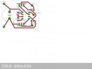
I did have a backup plan I drew the IR2153 schematic on eagle and was going to rout it out but a stepper driver board blew so waiting for a new one at
the moment.
All of the bits are organized got a fx2240 fp4 transformer pot core and bobbin + a 10x25 round ferrite rod to try and make a 4000v transformer I
pulled apart one of those ebay hv units and they are 20 primary 1800 secondary windings was a bit of a job counting the windings coming off the
former.
Cheers nuxy.
Edit. I looked at the 12/220 inverter transistor markings looks like they are a chinese copy of 2sb1274 transistor it is pnp ,20 watts, and 100mhz
frequency , I have also attached the data sheet . nuxy
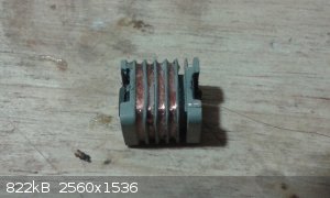 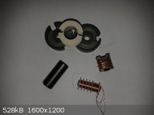
Attachment: datasheet.pdf (88kB)
This file has been downloaded 535 times
[Edited on 21-7-2015 by nux vomica]
|
|
|
nux vomica
Hazard to Others
  
Posts: 267
Registered: 18-7-2013
Member Is Offline
Mood: No Mood
|
|
Quote: Originally posted by Hennig Brand  | Yes we use that expression. I think you had some idea of what you were looking for though, so it probably wasn't completely luck. I actually ordered a
couple of those maybe a week or two ago when you first told me about them. I don't really need them at the moment, but I will add them to my
collection of "toys" for possible later use.  |
If you keep on doing a noah and collecting two of everything you will have a full ship soon. and don't they reckon were going to be flooded soon from
global warming melting the icecaps.
[Edited on 22-7-2015 by nux vomica]
|
|
|
markx
National Hazard
   
Posts: 649
Registered: 7-8-2003
Location: Northern kingdom
Member Is Offline
Mood: Very Jolly
|
|
Quote: Originally posted by nux vomica  | I did have a backup plan I drew the IR2153 schematic on eagle and was going to rout it out but a stepper driver board blew so waiting for a new one at
the moment.
All of the bits are organized got a fx2240 fp4 transformer pot core and bobbin + a 10x25 round ferrite rod to try and make a 4000v transformer I
pulled apart one of those ebay hv units and they are 20 primary 1800 secondary windings was a bit of a job counting the windings coming off the
former.
|
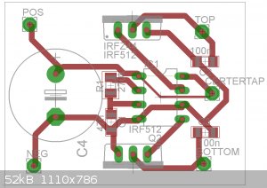
Looking at your pcb layout I see 2 problems :
a) pin 8 of the driver IC has to be connected to pin 1
b) pin 4 has to be connected to ground terminal (pin 6)
Also you might consider adding 10 ohm gate resistors to the fets. Also adding a 10k ohm resistor between gate and source of fets is a good idea. It
will pull the gates down and keep switches closed in case the IC decides to malfunction or you switch the circuit on without the IC. The IR2153 is a
pretty sensitive chip towards overloads and I have burnt a load of them before realizing that current limiting and keeping the gates from floating are
essential for longevity of the circuit.
Considering the 100n snubber caps it is advantageous to add a series resistor to them (2-5ohm) it will provide current limiting for the caps and keep
them from overheating. The snubbers will charge and discharge with every cycle of the switch and can easily overheat if there is only the esr of the
cap to dissipate the energy.
With homewound transformers the snubber circuits can rarely be avoided as usually the parasitics are strongly present and voltage overshoot is heavy
in push-pull topology. Especially if the windings have less than ideal coupling or the core has leakage flux. The overshoot can be expected around
tree to five times the input voltage. So with a 12V source around 60V of overshoot on a mediocre transformer design is quite common. This will be on
borderline avalanche mode for the IRF44 and is likely to kill the swithches quite soon. High frequency transformers are wound in some complicated ways
by interleaving the primaries and secondaries and paralleling them (litz wire style) for improved electromagnetic coupling. So be prepared for some
fried switches and driver ICs in near future  ! Keeping that in mind I would
suggest to use a dip socket for the IC and position the fets so that they can be easily desoldered for replacements. Also please add a fuse into the
incoming dc bus....it will do wonders to save everything from burning down like a merry hell when the fets blow and short the battery through the
transformer primary. Don't ask how I know this ! Keeping that in mind I would
suggest to use a dip socket for the IC and position the fets so that they can be easily desoldered for replacements. Also please add a fuse into the
incoming dc bus....it will do wonders to save everything from burning down like a merry hell when the fets blow and short the battery through the
transformer primary. Don't ask how I know this  
Exact science is a figment of imagination.......
|
|
|
nux vomica
Hazard to Others
  
Posts: 267
Registered: 18-7-2013
Member Is Offline
Mood: No Mood
|
|
Your quite right markx I missed 1/8 didn't rout and ive added the other earth wire, thanks I will look at the other suggestions nuxy
[Edit fixed points markx pointed out will work on other points.]
[Edited on 21-7-2015 by nux vomica]
|
|
|
markx
National Hazard
   
Posts: 649
Registered: 7-8-2003
Location: Northern kingdom
Member Is Offline
Mood: Very Jolly
|
|
Quote: Originally posted by nux vomica  | | Your quite right markx I missed 1/8 didn't rout and ive added the other earth wire, thanks I will look at the other suggestions nuxy
|
Glad I could be of help before you routed the board...although it would have been an easy fix even so  But it is always great when things work on the first attempt. But it is always great when things work on the first attempt.
I've been messing around with inverter designs quite a lot and know how easily they can blow up and how exponentially more complicated it all gets
when the output power rises and stability becomes an issue. Transformer design and snubbing of the switches are key elements if any significant power
output is needed. One can also choose more rugged switching elements with a higher voltage rating, but with mosfets this automatically means a higher
on state resistance and hence lower efficacy with way more overheating issues. IGBTs are also a robust option with the same driver circuitry, but
they tend to cost more than mosfets. And one has to keep track of the gate capacitance value as by using transistors with higher gate capacitance one
may overshoot the driver IC current rating and blow it all to hell again. In that case an additional high current driver chip is needed....like IR2110
e.g.
Exact science is a figment of imagination.......
|
|
|
Hennig Brand
International Hazard
    
Posts: 1284
Registered: 7-6-2009
Member Is Offline
Mood: No Mood
|
|
Quote: Originally posted by nux vomica  |
If you keep on doing a noah and collecting two of everything you will have a full ship soon. and don't they reckon were going to be flooded soon from
global warming melting the icecaps hennig what are you doing? control yourself.
|
I know what you mean, storage can be a problem. I really like to collect science and technology stuff. Any project I am working on, that works out
well, I immediately want to stock up on the associated components and materials. Being able to do things gives me a sense of power and accomplishment
I guess. Also, there are far worse things to spend one's time and money on.
Markx, thanks for the insights into homebrew inverters, I just learned a few things. So far that 555 based inverter I made is working fine, but the
current draw is fairly low. Also the 15kHz switching frequency is low enough that even amateur standard parallel, layer, wound transformers normally
work reasonably well (from what I have seen). Things do get tricky at much higher frequencies from what I have read and heard, as you have also
stated.
"A risk-free world is a very dull world, one from which we are apt to learn little of consequence." -Geerat Vermeij
|
|
|
nux vomica
Hazard to Others
  
Posts: 267
Registered: 18-7-2013
Member Is Offline
Mood: No Mood
|
|
Quote: Originally posted by Hennig Brand  | Quote: Originally posted by nux vomica  |
If you keep on doing a noah and collecting two of everything you will have a full ship soon. and don't they reckon were going to be flooded soon from
global warming melting the icecaps hennig what are you doing? control yourself.
|
I know what you mean, storage can be a problem. I really like to collect science and technology stuff. Any project I am working on, that works out
well, I immediately want to stock up on the associated components and materials. Being able to do things gives me a sense of power and accomplishment
I guess. Also, there are far worse things to spend one's time and money on.
|
Hennig if you have taken me the wrong way don't ,what you do with your life is your personal business so if I offended you I apologize and will keep
the wisecracks to myself . Nuxy
|
|
|
markx
National Hazard
   
Posts: 649
Registered: 7-8-2003
Location: Northern kingdom
Member Is Offline
Mood: Very Jolly
|
|
Quote: Originally posted by Hennig Brand  |
Markx, thanks for the insights into homebrew inverters, I just learned a few things. So far that 555 based inverter I made is working fine, but the
current draw is fairly low. Also the 15kHz switching frequency is low enough that even amateur standard parallel, layer, wound transformers normally
work reasonably well (from what I have seen). Things do get tricky at much higher frequencies from what I have read and heard, as you have also
stated. |
15kHz is way low for contemporary standards and really offers no advatages in terms of transformer or circuitry design. It only offers the
disadvantage of saturating your transformer core at a rather negligible power output and overheating/blowing the switching elements and driver
circuitry due to that. That is another point where the gate resistor can save a lot as a current limiter. If the junction blows and the IC is
connected to the switch without the resistor, you basically short out the output of the driver chip and 99% it means that the chip gives up the ghost.
If current limiting is provided then the driver circuitry has a good chance of living through it in my practical experience.
One can comfortably shoot for 40-50kHz of primary switching frequency without any further complications and gain a load of output power capacity from
the same size ferrite core. Going into the >100kHz primary switching is where the complications tend to arise (litz wire, paralleling of windings
and serious skin effect limitations), but there really is no need for such high frequencies. Most contemporary inverter designs do hover near the
50kHz primary switching speed....it tends to be the golden middle way between good efficacy, simple design and a broad range of affordable switching
elements. For example most generic IGBTs are not really good for anything upwards 50kHz....the charge carrier recombination in the junction limits the
turn on/off speed and you get high switching losses and cross conduction of the bridge by driving them too fast. Mosfets on the other hand do not
suffer from that particular shortcoming and can comfortably go up into hundreds of kHz range.
[Edited on 22-7-2015 by markx]
Exact science is a figment of imagination.......
|
|
|
retrofit
Harmless

Posts: 7
Registered: 12-7-2015
Member Is Offline
Mood: No Mood
|
|
Edit: The capacitance values given here are wrong. C3 is 711nF nominally, C1 and C2 are each 237nF nominal. That means (1/2) *
(711nF) * (3850 volts)^2 = 5.3 joules. 5.3 joules over 10uS is 530kW.
I finished putting together the voltage multiplier, constructing a trigatron (tube, electrodes, piezo igniter), and wiring all the pieces together. I
haven't yet tested a discharge of the full capacitor bank (will do tomorrow). I just wanted to see if anyone had any comments or suggestions about the
circuit.
The AC source is a small 12 VDC battery-powered inverter, putting out ~123 VAC at 60Hz (not ideal; as noted before, this requires a large capacitance
in the voltage multiplier). The microwave oven transformer (MOT) has roughly a 16.6x step-up. After the single stage, half-wave voltage multiplier,
the calculated voltage (extrapolated from lower voltage testing) is around 3850 VDC which charges up C3. R1 is a 50 ohm, 10 watt resistor (which, as I
look at my board again, is actually on the bottom, between C2/D2 and C3/L1, not up top there). All caps are arranged to be rated for 4kV; all diodes
are 12kV rated.
I didn't have a symbol in my parts library for the trigatron, so I just put a push button switch in the schematic. Not pictured is a 100 ohm, 10 watt
resistor in series with the piezo igniter to encourage the capacitor bank (C3) to discharge through the load and not myself. The gap is set at 3mm
(est. 9 kV breakdown voltage in air), and the piezo reliably sparks across the gap. I read that most trigatrons are operated within 80% or so of
breakdown voltage. Is that gap too large for fast switching? If I take 3850 V to be 80% of the gap's breakdown voltage (giving 4813 V), then I might
consider setting it to 1.6mm.
As an aside, I discovered that piezo igniter leads seem to be completely immune to my best attempts to solder to them. Improvisation of questionable
quality followed.
The load for tomorrow's dry run (no bridgewire) is just the primary of another MOT to provide some inductance and take a bit of stress off the caps.
In normal operation, that won't be present. I plan to use the primary because of the high surge current and thicker winding, but that will produce a
high voltage pulse at the secondary windings. which might arc over. Perhaps it would be better to use the secondary, creating a high current, lower
voltage pulse in the primary? All of this is irrelevant with a bridgewire in the system, because inductance appears to work against an EBW setup.
During normal operation, I was considering using that MOT to ballast the charging MOT--is it worth it?
As to energy/power output, 1/2 * 7.11uF * 3850 volts^2 ~= 52.69 joules. 52.69 joules over 10uS (pulled that out of thin air) should be 5.269 MW.
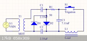
[Edited on 22-7-2015 by retrofit]
|
|
|
Hennig Brand
International Hazard
    
Posts: 1284
Registered: 7-6-2009
Member Is Offline
Mood: No Mood
|
|
Retrofit, I used an MOT and full wave multiplier earlier in this thread and it works but is very inefficient and big and heavy. Also your capacitor
has an awful lot of capacitance. Is it actually a pulse rated cap with low ESR and low ESL? Even with relatively low circuit resistance and inductance
most of the charge on that capacitor will not be transferred before bridgewire burst.
Quote: Originally posted by markx  |
15kHz is way low for contemporary standards and really offers no advatages in terms of transformer or circuitry design. It only offers the
disadvantage of saturating your transformer core at a rather negligible power output and overheating/blowing the switching elements and driver
circuitry due to that. That is another point where the gate resistor can save a lot as a current limiter. If the junction blows and the IC is
connected to the switch without the resistor, you basically short out the output of the driver chip and 99% it means that the chip gives up the ghost.
If current limiting is provided then the driver circuitry has a good chance of living through it in my practical experience.
One can comfortably shoot for 40-50kHz of primary switching frequency without any further complications and gain a load of output power capacity from
the same size ferrite core. Going into the >100kHz primary switching is where the complications tend to arise (litz wire, paralleling of windings
and serious skin effect limitations), but there really is no need for such high frequencies. Most contemporary inverter designs do hover near the
50kHz primary switching speed....it tends to be the golden middle way between good efficacy, simple design and a broad range of affordable switching
elements. For example most generic IGBTs are not really good for anything upwards 50kHz....the charge carrier recombination in the junction limits the
turn on/off speed and you get high switching losses and cross conduction of the bridge by driving them too fast. Mosfets on the other hand do not
suffer from that particular shortcoming and can comfortably go up into hundreds of kHz range.
|
No advantages? There are massive advantages going from 60Hz to 15kHz. Markx, check the Magnetics ferrite transformer design guide I posted here:
http://www.sciencemadness.org/talk/viewthread.php?tid=23466&...
With a 3019P pot core going from 20kHz to 50kHz increases the power handling capability from 48 Watts to 75 Watts. If the frequency is increased to
100kHz the power handling capability goes to 108W and at 250kHz, 210W. You are correct I could have used a higher frequency and reduced transformer
size and gained efficiency, but since I only need 5W or less and for only a very short duration how much practical difference does it make? Even going
with the relatively low frequency of 15kHz allows reasonably small capacitors to be used for the voltage multiplier and also reasonable efficiency at
the required current draw. I suppose battery life could be improved with higher frequency which is a consideration. If I was designing a 500W power
supply for continuous use I would be much more concerned with efficiency and keeping the component sizes as small as possible, but I am much less
concerned with a 5W power supply that is only run for 5-10 seconds every once in a while.
I am fairly new to inverter design and what I built is definitely not optimized, but it works and so far seems reliable.
[Edited on 22-7-2015 by Hennig Brand]
"A risk-free world is a very dull world, one from which we are apt to learn little of consequence." -Geerat Vermeij
|
|
|
| Pages:
1
..
5
6
7
8
9
..
11 |