| Pages:
1
2
3
4
..
11 |
Hennig Brand
International Hazard
    
Posts: 1284
Registered: 7-6-2009
Member Is Offline
Mood: No Mood
|
|
Simple Trigatron Trigger Pulse Generator From Bug Zapper Power Supply
Yeah, I knew you meant Cooper. Thanks for that compressed file, it has a lot of good stuff in it. I have been mulling the triggered switch thing over
for the last couple of days. Just about ready to give something a try.
I already linked to this page earlier, but after looking at the one-shot trigatron pulse generator on that page I got a couple of ideas.
http://hotstreamer.deanostoybox.com/ross/projects/Pulse/puls...
Here is an image of the one-shot pulse generator from that page:
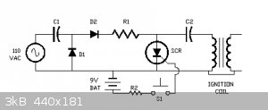
In order to keep things really simple the SCR was replaced with a static spark gap and the AC input and voltage doubler stage were replaced with the
ubiquitous bug zapper power supply. A single bug zapper supply, with proper adjustment, can easily charge a suitable capacitor to over a 1000 volts if
needed. The capacitor is charged through the primary winding of the transformer until the breakover voltage of the spark gap is reached which then
arcs over and dumps the stored charge through the transformer primary very rapidly which transfers the pulse by electromagnetic induction to the
transformer secondary and the trigatron trigger electrode.
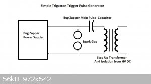
If more precise firing times are required replace the static spark gap with an SCR. Multiple circuits like this could be fired simultaneously using
SCRs. SCRs are sensitive to overvoltage, with ones I have commonly seen being rated for max 400V or sometimes 600V, so the capacitor and charging
circuit would need to be designed carefully so as not to create an over voltage situation unless very high voltage SCRs could be obtained. A pulse
capacitor charged to a lower voltage and a transformer with lower turns ratio (more voltage gain) would be needed.
I avoided winding a transformer by taking one from a switching supply, which seems to have a couple windings with a turns ratio (# turns in primary/#
turns in secondary) of 1/2-1/4 (estimated by spark gap length at secondary). This transformer is not designed to be used at several thousand volts,
but so far it seems to be holding up just fine. When I actually get it put together more properly I will post a picture or two.
BTW, a couple people have mentioned capacitor charging current limiting resistors. They are not needed when using the bug zapper supplies, since the
transformers themselves are made to be current limiting (or it just happened that way maybe).
I am pretty sure I can get by with just three bug zapper power supplies, as long as I go no higher than 3-4kV and a few uF of capacitance. Two in
series to charge the capacitor bank and one to fire the trigatron. If I was more clever, or motivated, I probably wouldn't even need the third one,
but they are only $3 each at the local dollar store anyway.
[Edited on 15-4-2015 by Hennig Brand]
"A risk-free world is a very dull world, one from which we are apt to learn little of consequence." -Geerat Vermeij
|
|
|
markx
National Hazard
   
Posts: 649
Registered: 7-8-2003
Location: Northern kingdom
Member Is Offline
Mood: Very Jolly
|
|
The last "single pulse" circuit with the spark gap will generate a very high frequency hv ac on the transformer secondary (the capacitor and primary
winding form a LC resonant circuit as the gap fires and shorts the cap through the inductance)....it is actually the most classic setup for spark
triggered tig welder arcstarters. The high frequency ac is transferred to the welder circuit by an air core transformer. In fact the resonant ac is
usually of such high frequency that it will flow by the semiconductor junctions (paracitic capacitance of the junction will conduct it) and will not
harm them. It will also not produce a classic electric shock in you body if you should touch the secondary while the gap fires. Actually one can
barely feel it due to the skin effect....it still can burn your skin if enough power is applied.
Exact science is a figment of imagination.......
|
|
|
Hennig Brand
International Hazard
    
Posts: 1284
Registered: 7-6-2009
Member Is Offline
Mood: No Mood
|
|
Interesting, it should work fine then. I have seen the same thing done with stunguns, which is where I got the idea. The stun gun I made this way sure
had one hell of a bite to it though. It is current not voltage that does the damage and the arc starter probably had very low current as well as high
frequency. From what I have seen, it takes very little current to trigger a trigatron as well. The above linked to website suggested using a 1uF,
400v, pulse cap before the automotive ignition coil, they were using, which would then boost the voltage up to as high as 30kV, so the current was
really very low and it sounded from the description that an even smaller capacitor could probably be used with good results. Those guys were playing
with some big capacitor banks and trigatrons too (coin shrinking, etc).
Thought I would mention that from what I have read so far voltages below the main electrode (capacitor(s)) voltage are normally used to fire the
trigatron and that using voltages well above are not needed and can actually cause problems.
[Edited on 16-4-2015 by Hennig Brand]
"A risk-free world is a very dull world, one from which we are apt to learn little of consequence." -Geerat Vermeij
|
|
|
aga
Forum Drunkard
    
Posts: 7030
Registered: 25-3-2014
Member Is Offline
|
|
Sorry if i have this backwards, but you guys just want a localised high voltage pulse no ?
Why is it necessary to waste all that energy along long wires ?
Why not incorporate some cpu power/battery nearer to the device you want to detonate, and put that in control of the detonation ?
The wire, or wireless part of the system would be standard comms stuff.
|
|
|
Hennig Brand
International Hazard
    
Posts: 1284
Registered: 7-6-2009
Member Is Offline
Mood: No Mood
|
|
Unless you are going to replace the capacitor bank and main high voltage & high current switch with every shot fired there needs to be at least
some distance between the main power module and the blast. Yes, the capacitor bank discharge (the switch) could be controlled remotely through small
gauge wire. That is how it is done by the professionals when they need to put more distance between them and the blast than is practical with the
heavy low loss lines from what I understand. There is a page in that compression file, posted by Jock88, which shows or describes a commercial
blasting box being controlled remotely by wire, but there still always needs to be at least some wire between the box and the blast unless you don't
mind losing it as I said (preferably low resistance, low inductance, HV wire for low losses).
A battery or regular power supply can't supply nearly a large enough di/dt. There needs to be a massive pulse of current with extremely fast rise time
to get a shock wave from the exploding wire capable of initiating a secondary explosive. I think you are thinking of regular low voltage resistive
type electric detonators. And in that case I would use/have used one or more long extension cords and a cordless drill battery. Even from a couple
hundred feet away or more it works perfectly since an amp or less is all that is needed to fire them properly. However, we are then back to using
primaries again.
1200V, 25A SCR
It seems higher voltage SCRs are not that hard to get and they can be quite affordable too. I think I will be replacing the spark gap in the trigatron
trigger pulse generator with one of these SCRs either set up as a one shot for precise firing times or set up for repetitive pulses triggered by a
DIAC.
http://www.ebay.com/itm/10-pcs-NEW-ST-TYN1225-SCR-25A-1200V-...
Constructing Bridgewire Heads
It can be a bit challenging attaching the bridgewires to the lead posts/wires when constructing a bridgewire head. One of the big problems I have
noticed was that solder will tend to flow out onto the copper bridge wire when soldering. I found a good webpage which describes methods to
effectively prevent solder from flowing where it is not wanted.
http://www.ganoksin.com/borisat/nenam/solder-flow-clb.htm
Here is a copy/paste from there:
"
While goldsmiths normally strive to have their solder flow easily, there are times you don't want it to flow, such as spilling over a decorated
surface, if it 'freezes' a mechanism, or if it threatens to open a gap in a seam soldered earlier in a construction.
The best way of not melting earlier seams is to learn heat control and use heat sinks creatively to suck heat from the immediate area where the
threatened join is. I use small blocks of steel for this purpose. Repair jewelers sometimes use stacks of copper pennies as heat sinks - but make sure
they are pre-1974 or so ( as later ones have zinc cores which can melt out suddenly with unfortunate consequences. A solder's melting temperature
rises every time it is heated so there is the (admittedly mostly mental) assistance of earlier seams melting at a higher temperature than the same
solder you are using again for a join.
Heat sinks won't work well with silver objects, as silver conducts heat so rapidly. Instead, for silver constructions and for especially delicate jobs
a solder flow retardant can be really useful. A paint-on solder flow retardant is easiest to use.
There are commercial solder flow retardants, but I've never needed to use them. Here are some of the ways that goldsmiths use to prevent solder
flowing.
Polishing Machine Rouge: Some people use a little rouge powder from the polishing machine dust mixed with a small amount of oil which works well. Jeff
Demand of Toronto likes to make a heat the rouge until it melts and then paint it on.
Pencil Lead: a graphite stick or soft pencil will leave a barrier that solder won't flow across. Pencil leads also work to line up tube sections when
constructing a hinge. Liquid graphite lubricant that can be found in for automotive supply stores can be used.
Scrap of Rubber: One can take a small piece of rubber (vulcanized mold chunk, a slice off a piece of an old torch hose etc) and, holding it in
tweezers, rub it on the metal part to be protected while it is hot. The rubber melts on with a truly nasty smell (use ventilation) and leaves a brown
slimy coat on the metal. This too works well.
Yellow Ochre: Old timers used yellow ochre with water. I find that it has a tendency to "bleed" into the flux and make the soldering problematic. It
is somewhat better mixed with a little oil instead of water but I find it difficult to remove from the piece and do not use it.
Maalox® and "White-Out": My favorite is Papermate© correction fluid. There are solvent based and solvent-free water based versions. In my experience
the water based version does not come off the metal after soldering as easily as the solvent based one. I like the solvent based one for this reason.
I wrote to the Papermate company listing all the metals, chemicals and temperatures that their product would come in contact with in standard use by
metalsmiths. In their return letter no mention of chemical interactions with the white pigment was made and they felt the main danger lay in the
solvent used: 1.1.1. trichloroethylene which is a mutagen and carcinogen. This leads me to think that the white material is something inert (chalk).
1.1.1. trichloroethylene breaks down when heated to form chlorine gas, hydrogen chloride and phosgene gas, all highly toxic. Their lab ran evaporation
rate tests and found that because it skins over the solvent does not evaporate as quickly as they had thought. About twenty minutes after application
the solvent will for all intents and purposes have evaporated. There is a safety problem here: it would be wise to use water rather than solvent based
materials. Ceramist's 'kiln wash' might work in the same way.
I have a suspicion that Papermate® and similar products are mostly calcium carbonate, what print makers call 'whiting;' and what the rest of us call
'chalk'. The cheapest source by volume for chalk in solution is probably Maalox® though I have not yet tried it as a solder flow retardant.
Robert Kaylor of Boise, Idaho uses China White, a standard graphic artists material made mostly of chalk as an effective solder flow retardant. It
comes as a liquid in a tube or in a dry cake which one uses like a water color cake with a brush and a little water. "
I think I will be using White-out to prevent the bridgewire from getting soldered in the middle and then removing it with solvent after soldering. I
solvent wash would be a good thing after soldering anyway I think.
[Edited on 16-4-2015 by Hennig Brand]
"A risk-free world is a very dull world, one from which we are apt to learn little of consequence." -Geerat Vermeij
|
|
|
nux vomica
Hazard to Others
  
Posts: 267
Registered: 18-7-2013
Member Is Offline
Mood: No Mood
|
|
pcb bridge wire
Hi everyone I might have an idea that I think will make fabricating the bridge wire part more easier and more consistent .
We make a small round circuit board with two pads to connect the wires to then have the bridgewire connecting between the pads the bridgewire can be
etched as small as needed and it can be gold plated and you can stencil resist over areas where you want to keep the solder if you make a double sided
board you can connect on one side of the board and the via will connect to the bridgewire side
Cheers nuxy
|
|
|
Hennig Brand
International Hazard
    
Posts: 1284
Registered: 7-6-2009
Member Is Offline
Mood: No Mood
|
|
I think the bridgewire should be up on posts with low density fine secondary explosive all around it. I was thinking along similar lines as you for a
while though. The other thing is that the bridge wire is normally 0.001 inch to 0.003 inch in diameter; 40 AWG is actually slightly bigger than 0.003
inch in diameter and that is tricky enough to deal with. Gold has less than half the tensile strength of copper, so it must need very special handling
equipment especially when it gets down to 0.001 inch.
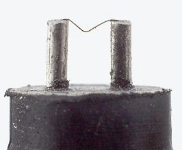
Then again maybe I am not right, here is a document showing the bridgewire positioned more or less right up against the plug.
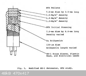
Attachment: High Temperature EBW Detonator.pdf (317kB)
This file has been downloaded 915 times
[Edited on 17-4-2015 by Hennig Brand]
"A risk-free world is a very dull world, one from which we are apt to learn little of consequence." -Geerat Vermeij
|
|
|
jock88
National Hazard
   
Posts: 505
Registered: 13-12-2012
Member Is Offline
Mood: No Mood
|
|
Quote: Originally posted by markx  | | The last "single pulse" circuit with the spark gap will generate a very high frequency hv ac on the transformer secondary (the capacitor and primary
winding form a LC resonant circuit as the gap fires and shorts the cap through the inductance)....it is actually the most classic setup for spark
triggered tig welder arcstarters. The high frequency ac is transferred to the welder circuit by an air core transformer. In fact the resonant ac is
usually of such high frequency that it will flow by the semiconductor junctions (paracitic capacitance of the junction will conduct it) and will not
harm them. It will also not produce a classic electric shock in you body if you should touch the secondary while the gap fires. Actually one can
barely feel it due to the skin effect....it still can burn your skin if enough power is applied. |
This would work OK so long a the 'ubiquitous bug zapper device' is dc (not ac). I don't know what they are?
As far as the 'best' wire to use, there was a patent put up on the board that had no bridge wire at all. The patent was restricted at the time because
it was when the bomb was being developed. It was filed in (about 44) and published in the seventies (about).
I'll have a look for if some time.
[Edited on 17-4-2015 by jock88]
|
|
|
Hennig Brand
International Hazard
    
Posts: 1284
Registered: 7-6-2009
Member Is Offline
Mood: No Mood
|
|
The bug zappers have a tiny flyback transformer in them, which produces AC, but the output is rectified to DC with HV diodes (the diode(s) also come
with the zappers). It has to be DC because the energy is stored in a capacitor like a coiled spring waiting for the unsuspecting bug to get between
the conductive mesh contacts and then to ride the lightning. 
"A risk-free world is a very dull world, one from which we are apt to learn little of consequence." -Geerat Vermeij
|
|
|
Hennig Brand
International Hazard
    
Posts: 1284
Registered: 7-6-2009
Member Is Offline
Mood: No Mood
|
|
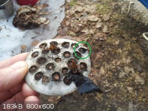
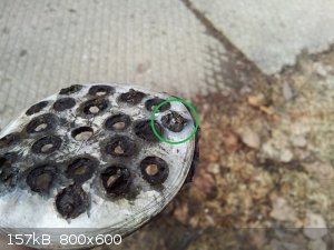
0.3g of ETN Initiated With 40 Gauge Copper EBW
EBW Head:
A half inch or so of hot melt glue stick was sliced off on a cutting board, drilled once and then drilled a second time, for lead wires, using a
previously made jig/spacer made from a piece of circuit board to give precise hole spacing. The bridge wire was ca. 40AWG copper of about 2 to 2.5mm
length. The white-out solder flow retardant worked beautifully preventing any solder from flowing out onto the middle of the bridgewire. It could also
be easily removed with acetone which made it very soft so that it could be gently wiped away. A fine cotton swab soaked in acetone would likely be
effective and gentle. Once a few tricks are learned EBW head construction is not that difficult. The EBW head was pressed into the fluffy ETN with
light finger pressure only.
Charge:
0.3g of ETN pressed in three increments into a 7.6mm Al casing; 0.1g at about 30lbs, 0.1g at about 15lbs and 0.1g with only finger pressure to remove
voids and settle the ETN. The ETN was very light and fluffy, the result of rapid precipitation from dilution of a well mixed solution in methanol with
water.
Transmission Line:
12ft of RG-6 coax (satellite/cable television coax) and 1ft of 18AWG speaker wire. Total 13ft of transmission line.
Capacitor Bank:
6X 1uF, 1000V connected to give 0.67uF and 3000V. The bank was charged to only 2300V for this test. The voltage divider allows a much lower and very
safe proportional voltage to be monitored with a regular multimeter/volt meter and from a distance with a fine sensing wire if desired. The voltage
divider also doubles as a bleeder resistor ensuring that the capacitor bank is fairly quickly discharged after use.
Switching:
Switching was accomplished by the very crude and inefficient method of touching the center conductor of the coax to the speaker wire connected to the
capacitor bank.
Target:
Ca. 2.6mm steel plate.
Results:
It was a very loud boom, which I could tell clearly even though I was wearing earmuffs (I was only 10ft away of course). The result, in terms of steel
penetration & shattering, would have been better if the bottom increment(s) of ETN had been pressed to much higher density with a press and of
course if more ETN had been used. This test was simply proof of concept.
Very large capacitors are not needed at all. The most important thing is to have low impedance cable that isn't too long, good low inductance &
resistance connections and high voltage. I have 100ft of RG-213 ordered which I will have soon, as well as enough new pulse capacitors to make a low
ERS capacitor bank of 1.2uF and 4000V. I don't think I will have any trouble initiating these homemade EBW detonators through 100ft of RG-213 since it
is a very low loss cable.
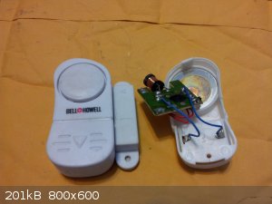
BTW, a good source of ca. 40AWG copper magnet wire is the little door and window alarms which are often available at dollar stores and hardware
stores, etc. Don’t let the small size fool you, the inductor that is in them holds a lot of magnet wire. About ten years ago I decided to make a
2-3V relay from a reed switch and the magnet wire on one of those inductors. It seemed like I was winding for hours though I guess it couldn’t have
been; it was really surprising how long the wire was that makes up those windings. The insulation can be easily burned off with a low flame of a small
butane torch. Even a mini butane torch can melt the fine copper wire if care is not used.
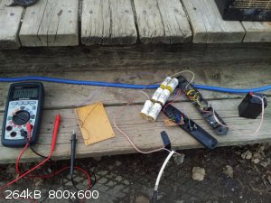 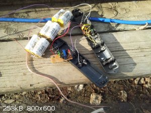  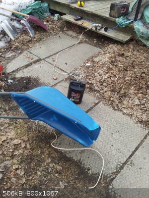 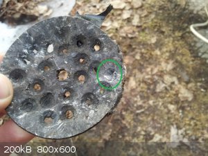   
[Edited on 18-4-2015 by Hennig Brand]
"A risk-free world is a very dull world, one from which we are apt to learn little of consequence." -Geerat Vermeij
|
|
|
nux vomica
Hazard to Others
  
Posts: 267
Registered: 18-7-2013
Member Is Offline
Mood: No Mood
|
|
Hi I've drawn up a drawing of how I see the bridgewire head made from a fiberglass pcb cheers nuxy

|
|
|
Hennig Brand
International Hazard
    
Posts: 1284
Registered: 7-6-2009
Member Is Offline
Mood: No Mood
|
|
Interesting ideas. I can see the third one working, but I think it would be very difficult for most amateurs to accurately and precisely make
0.001-0.003inch diameter strips in comparison to just obtaining some fine gauge wire with consistent diameter.
"A risk-free world is a very dull world, one from which we are apt to learn little of consequence." -Geerat Vermeij
|
|
|
nux vomica
Hazard to Others
  
Posts: 267
Registered: 18-7-2013
Member Is Offline
Mood: No Mood
|
|
I realise that most people would be put off making there own pcb,s but I have made them at home that had all smt components on them I made the uv
resist transparency's and the solder paste stencils myself.
Also there is a lot of free programs online (eagle cad is one) for free that you can draw up your board then send it off to a pcb manufacture in
china and get it fabricated very cheaply nowadays.
I've got a cnc router at home so I can mill the board, I've got some carbide bits that are .5mm in dia , but I admit the stencil for the green resist
coat is a bit more challenging to fabricate.
cheers nuxy.
|
|
|
jock88
National Hazard
   
Posts: 505
Registered: 13-12-2012
Member Is Offline
Mood: No Mood
|
|
You can purchase very fine Nichrome wire. It may the more resistant to corrosion for a more long term device. Copper is somewhat reactive with a very
thin wire(or is it?).
The extra resistance of the tiny piece of Nichrome would be irrelevant.
|
|
|
Hennig Brand
International Hazard
    
Posts: 1284
Registered: 7-6-2009
Member Is Offline
Mood: No Mood
|
|
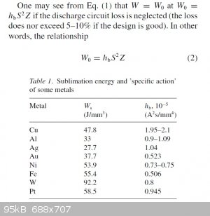
Energy Injected to the Wire During the First Current Pulse
The following snip-it and table were taken from, "Electric Explosion of Wires as a Method for Preparation of Nanopowders" by Yu A. Kotov. The article
is attached below as well.
"
The energy W injected to the wire during the first current pulse was found to be
W = (hb * W0 * S^2 * Z)^0.5
where W0 = 1/2CVo^2 is the stored energy, J; Vo is the capacitor charging voltage, kV; Z = (L/C)^0.5 is the circuit characteristic impedance, Ohm; L is the discharge circuit
inductance, μH; C is the capacitance, μF; S = 1/4 * pi * D^2 is the wire cross-sectional area, mm2 (D being the wire diameter, mm); hb has the dimensionality of A^2 * s / mm4 and represents the pre-explosion specific ‘action’ or thermal toughness
of the material heated with a current pulse (Anderson&Neilson, 1959; Cnare & Neilson, 1959; Cnare, 1961). This notion was used earlier
(Rudenberg, 1950) for calculation of safety fuses. The obtained hb values (Anderson & Neilson, 1959;
Cnare&Neilson, 1959; Tucker&Neilson, 1959; Cnare, 1961; Kotov et al., 1990) are given in Table 1."
Attachment: Electric Explosions of Wires as a Method of Preparation of Nanopowders.pdf (208kB)
This file has been downloaded 1212 times
hb(Copper) / hb(Gold) = ca. 4
All other things being equal, it seems as though it takes roughly four times the energy to explode a copper bridgewire than it takes for a gold one.
Of course, all other things being equal, a change in the diameter of the bridge wire by a factor of two would change the burst energy by a factor of
sixteen.
Quote: Originally posted by jock88  |
You can purchase very fine Nichrome wire. It may the more resistant to corrosion for a more long term device. Copper is somewhat reactive with a very
thin wire(or is it?).
The extra resistance of the tiny piece of Nichrome would be irrelevant. |
Nichrome is much more corrosion resistant, but is not very suitable other than that from the few things I have read (very high resistivity for one).
Copper is quite suitable, except for the corrosion issue and its much lower density than gold as well.
[Edited on 19-4-2015 by Hennig Brand]
"A risk-free world is a very dull world, one from which we are apt to learn little of consequence." -Geerat Vermeij
|
|
|
jock88
National Hazard
   
Posts: 505
Registered: 13-12-2012
Member Is Offline
Mood: No Mood
|
|
"All other things being equal, it seems as though it takes roughly four times the energy to explode a copper bridgewire than it takes for a gold one."
Since nickle has a value closer to gold (and assuming chromium's figure is not too bad) then nichrome should not be too bad?
Patent of spark gap detonator (no wire 'ebw') attached.
The filed and publication dates are very different.
Attachment: US3955505.pdf (188kB)
This file has been downloaded 851 times
[Edited on 18-4-2015 by jock88]
|
|
|
Hennig Brand
International Hazard
    
Posts: 1284
Registered: 7-6-2009
Member Is Offline
Mood: No Mood
|
|
40 gauge nichrome wire resistance at 20C = ca. 70 ohms/ft
40 gauge gold wire resistance at 20C = ca. 1.49 ohms/ft
40 gauge copper wire resistance at 20C = ca. 1.05 ohms/ft
I = V / R
Initial current flow = voltage of capacitor(s) / resistance of system
Using nichrome resistance wire would add a lot of unwanted resistance to the system which would greatly decrease current flow for a given voltage.
Even a 2mm long nichrome bridge wire (40 gauge) would add about 0.46 ohms of resistance to the system, while 100ft of RG-213 cable only adds about 0.3
ohms of resistance. The tiny 2mm long nichrome wire could easily have more resistance than the whole rest of the system!
Attachment: Initiation of Exposives by Exploding Wires I (Effect of Circuit Inductance).pdf (1.7MB)
This file has been downloaded 953 times
Attachment: Initiation of Explosives by Exploding Wires II (Effect of Circuit Resistance).pdf (1.1MB)
This file has been downloaded 897 times
Attachment: Initiation of Explosives by Exploding Wires III (Effect of Wire Diameter).pdf (1.1MB)
This file has been downloaded 858 times
Attachment: Initiation of Explosives by Exploding Wires IV (Effect of Wire Length).pdf (755kB)
This file has been downloaded 794 times
Attachment: Initiation of Explosives by Exploding Wires V (Effect of Wire Material).pdf (1.3MB)
This file has been downloaded 960 times
Attachment: Initiation of Explosives by Exploding Wires VI (Further Effects of Wire Material).pdf (1.2MB)
This file has been downloaded 816 times
Attachment: Initiation of Explosives by Exploding Wires VII (Effect of Energy Termination).pdf (1.2MB)
This file has been downloaded 878 times
Attachment: Initiation of Explosives by Exploding Wires VIII (Effect of Moderate Voltage Levels).pdf (865kB)
This file has been downloaded 894 times
[Edited on 19-4-2015 by Hennig Brand]
"A risk-free world is a very dull world, one from which we are apt to learn little of consequence." -Geerat Vermeij
|
|
|
Hennig Brand
International Hazard
    
Posts: 1284
Registered: 7-6-2009
Member Is Offline
Mood: No Mood
|
|
This has some useful information in it, though quite general.
Attachment: High Voltage Surge Generators - HV Engineering Chapter 8.pdf (207kB)
This file has been downloaded 1597 times
From "Military Explosives" page 8-17, regarding compatibility of PETN and copper.
"
At temperatures up to about 50°C, dry PETN does not react with copper, brass, aluminum, magnesium, magnesium-aluminum alloys, stainless steel, mild
steel, mild steel coated with acid proof black paint, and mild steel plated with copper, cadmium, nickel or zinc. Wet PETN does not react with
stainless steel, and aluminum is affected only slightly after long periods of storage. However copper, brass, magnesium, magnesium-aluminum alloys,
mild steel, mild steel coated with acid-proof black paint, and mild steel plated with cadmium, copper, nickel or zinc are affected. PETN is used in
the explosive core of industrial detonating fuses, in the charge of commercial blasting caps, and as the entire explosive charge in exploding bridge
wire detonators."
[Edited on 19-4-2015 by Hennig Brand]
"A risk-free world is a very dull world, one from which we are apt to learn little of consequence." -Geerat Vermeij
|
|
|
markx
National Hazard
   
Posts: 649
Registered: 7-8-2003
Location: Northern kingdom
Member Is Offline
Mood: Very Jolly
|
|
I see you still refuse to show mercy to this mangled corpse of a witness plate....hasn't the poor bastard suffered enough already?   
Cool capacitor bank btw...
Exact science is a figment of imagination.......
|
|
|
jock88
National Hazard
   
Posts: 505
Registered: 13-12-2012
Member Is Offline
Mood: No Mood
|
|
It's a very holy plate.
|
|
|
Hennig Brand
International Hazard
    
Posts: 1284
Registered: 7-6-2009
Member Is Offline
Mood: No Mood
|
|
I am going to use it for a strainer when I am done. 
No, seriously, it seems when I go looking for a witness plate that one keeps turning up. Just like a bad penny! 
Here are a couple snip-its which show how even relatively small increases in explosive density make initiation of secondary explosives by EBW much
more difficult. The first snip-it is from Cooper and the second is from "Exploding Wires Vol 4".
 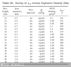
[Edited on 21-4-2015 by Hennig Brand]
"A risk-free world is a very dull world, one from which we are apt to learn little of consequence." -Geerat Vermeij
|
|
|
aga
Forum Drunkard
    
Posts: 7030
Registered: 25-3-2014
Member Is Offline
|
|
Sorry if this sounds dense.
To detonate [whatever] are you just looking for a hot wire, or a Very hot wire that gets very hot very fast, or an Extremely hot wire that gets hot
extremely fast ?
I know nothing about explosives, but do know about wires getting hot.
[Edited on 20-4-2015 by aga]
|
|
|
Hennig Brand
International Hazard
    
Posts: 1284
Registered: 7-6-2009
Member Is Offline
Mood: No Mood
|
|
The following are the first ten pages from one of the RISI technical sections from their site. Read page three for a good basic description of the
difference between regular low power electrical igniters and exploding bridge wire secondary explosive initiators.
Attachment: page1.pdf (28kB)
This file has been downloaded 858 times
Attachment: page2.pdf (33kB)
This file has been downloaded 928 times
Attachment: page3.pdf (32kB)
This file has been downloaded 994 times
Attachment: page4.pdf (40kB)
This file has been downloaded 1081 times
Attachment: page5.pdf (33kB)
This file has been downloaded 741 times
Attachment: page6.pdf (35kB)
This file has been downloaded 939 times
Attachment: page7.pdf (33kB)
This file has been downloaded 902 times
Attachment: page8.pdf (30kB)
This file has been downloaded 1055 times
Attachment: page9.pdf (29kB)
This file has been downloaded 887 times
Attachment: page10.pdf (159kB)
This file has been downloaded 799 times
"A risk-free world is a very dull world, one from which we are apt to learn little of consequence." -Geerat Vermeij
|
|
|
aga
Forum Drunkard
    
Posts: 7030
Registered: 25-3-2014
Member Is Offline
|
|
WOW.
Thanks for the references.
|
|
|
Hennig Brand
International Hazard
    
Posts: 1284
Registered: 7-6-2009
Member Is Offline
Mood: No Mood
|
|
You are welcome.
"A risk-free world is a very dull world, one from which we are apt to learn little of consequence." -Geerat Vermeij
|
|
|
| Pages:
1
2
3
4
..
11 |