| Pages:
1
2
3
..
11 |
Forumdude
Harmless

Posts: 43
Registered: 6-2-2013
Member Is Offline
Mood: No Mood
|
|
Has anyone made a EBW setup.
I have looked around and there isnt much information on how to make one of these or how many volts and joules ect and what kinds of wire will work for
the actual EBW and the wires leading from it.
|
|
|
Phantom
Harmless

Posts: 43
Registered: 26-4-2011
Member Is Offline
Mood: AUDENDUM EST,FORTES AUDIUVAT IPSE DEUS
|
|
http://www.sciencemadness.org/talk/viewthread.php?tid=15317
https://www.sciencemadness.org/whisper/viewthread.php?tid=12...
Adrenaline filled experimentalism.
|
|
|
Forumdude
Harmless

Posts: 43
Registered: 6-2-2013
Member Is Offline
Mood: No Mood
|
|
Thank you so much! I searched EBW on here and those pages didnt come up.
|
|
|
Forumdude
Harmless

Posts: 43
Registered: 6-2-2013
Member Is Offline
Mood: No Mood
|
|
Thing is though I have no electrical experience and I have no clue as to what they are discussing
|
|
|
Ral123
National Hazard
   
Posts: 735
Registered: 31-12-2011
Member Is Offline
Mood: No Mood
|
|
I like your sense of humour 
|
|
|
hissingnoise
International Hazard
    
Posts: 3940
Registered: 26-12-2002
Member Is Offline
Mood: Pulverulescent!
|
|
Yeah, that is funny . . .
|
|
|
Fuse
Harmless

Posts: 16
Registered: 25-2-2013
Member Is Offline
Mood: No Mood
|
|
I've built one, some videos posted on youtube with "Freepatentsonline" nick.
|
|
|
franklyn
International Hazard
    
Posts: 3026
Registered: 30-5-2006
Location: Da Big Apple
Member Is Offline
Mood: No Mood
|
|
Seems you need to read a lot more on this topic.
A Guide to Explosives Firing
www.dtic.mil/dtic/tr/fulltext/u2/a322055.pdf
If you want a second opinion _
www.amateurpyro.com/forums/topic/414-ebws-capacitor-discharg...
_______________________________________________________
While on the topic I thought this an interesting development , it's a device that
amplifies the power from a normal blasting machine producing a pulse to fire EBW's.
Blasting Machine Power Multipliers for EBW's
www.teledynerisi.com/1techtopics/pdf/0295.pdf
www.teledynerisi.com/products/0products_2fs_page43.asp
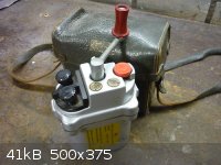
The above would be used for example with a blasting machine like this_
http://cgi.ebay.com/ws/eBayISAPI.dll?ViewItem&item=26117...
.
|
|
|
Fuse
Harmless

Posts: 16
Registered: 25-2-2013
Member Is Offline
Mood: No Mood
|
|
http://www.youtube.com/watch?v=IXMDltOiNpU
With this I detonate ETN directly 
|
|
|
Ral123
National Hazard
   
Posts: 735
Registered: 31-12-2011
Member Is Offline
Mood: No Mood
|
|
Are these things reliable? In a way you use electrical energy in the battery to do the job of the primary. How many joules you put in each shot? Did
you make experiments with other secondaries?
|
|
|
Fuse
Harmless

Posts: 16
Registered: 25-2-2013
Member Is Offline
Mood: No Mood
|
|
The energy stored in the capacitor is 8J, from that you can transfer about 0,5-1J into exploding wire
(see http://www.dtic.mil/dtic/tr/fulltext/u2/609449.pdf).
Reliability is 100% for me; at the moment more than 50 test never failed.
Unfotunately I never tried with others primary.
In the future I will try to detonate a very insensitive material like AN-AL.
(see patent US 3,156,186)
If it works I can remove every type of primary 
|
|
|
Ral123
National Hazard
   
Posts: 735
Registered: 31-12-2011
Member Is Offline
Mood: No Mood
|
|
Nice, I'd use azide with the wire for critical applications to be sure. Interesting, 1J makes that thing explode, and with enough force to initiate
the ETN. I wonder how will it perform in winter at -20, specially if the ETN has previously been a little melted from the heat of the sun near a
window 
|
|
|
Forumdude
Harmless

Posts: 43
Registered: 6-2-2013
Member Is Offline
Mood: No Mood
|
|
Sorry I've been away but this is great information haha and and Fuse I have stumbled apoun your videos in the past ! Great stuff!
|
|
|
Hennig Brand
International Hazard
    
Posts: 1284
Registered: 7-6-2009
Member Is Offline
Mood: No Mood
|
|
EBW HV Power Supply from Handheld Bug Zapper Rackets
I have two hand held bug zappers that were given to me which had mechanical problems of some sort but the power supplies still work fine (is it a bad
sign that people keep giving me their old junk?). I also have 6 X 1000V, 1uF film capacitors which I removed from a large burned out VFD (variable
frequency drive) for large induction motor speed control found at a scrap yard years ago. I discovered that once the ca. 400V capacitors were removed
from these bug zapper power supplies that they could easily charge a several uF capacitor up to 1000V and that two of these in series could easily
charge up to 2000V. I haven't tried going much higher except by accident the 3X2 capacitor bank of 6X1000V, 1uF capacitors (total 2000V, 1.5uF) was
charged up to about 2200V once. Another 1000v, 1A diode (1N4007), was added in series with each of the two rectifier diodes present on each PS output.
So far I only have 40 gauge copper to make bridge wires and only RG6 coax (cable/satellite television cable) and/or speaker wire for transmission.
Charged up to 2000V the 1.5uF capacitor bank can easily detonate ETN through 1ft of 18 gauge speaker wire, however, attempting the same thing with
12ft of RG6 coaxial cable resulted in failures.
I am just getting my feet wet with this, but decided to post since I think it is interesting.
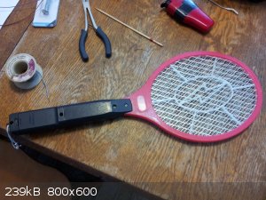 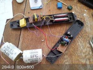 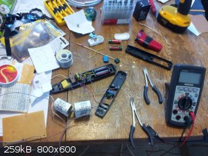
I know I should have bypass resistors in parallel with the two sets of series connected capacitors and on the rectifier diodes to ensure even
distribution of charge/voltage. I ordered some high voltage, high ohmic value, bleeder resistors today but they will be a while getting to me.
Ideally 4 or even 6kV would be much better than 2kV and if the bridge wire was closer to 50 gauge the power requirements would be much less than they
are now using a 40 gauge bridge wire. I think I have some heavy coaxial stored in a shed that was used by someone for Ham radio, which could be a big
improvement in the transmission department.
Another couple of bug zapper rackets and I am good to go for 4kV. 
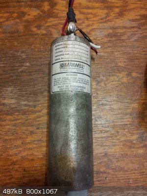
Does anyone know exactly what type of capacitor this is? The warning on it is a bit ominous and for good reason I guess. A couple of these in series
would be 12uF and could be charged to about 4kV. Now that is one hell of a jolt! I came into possession quite a few years ago of a lot of used 1970s
electronics and electrical equipment from personnel carriers, etc, when they were being refurbished; a certain piece, of which I had a few dozen I
think, had one of these big HV capacitors buried deep inside.
[Edited on 9-4-2015 by Hennig Brand]
"A risk-free world is a very dull world, one from which we are apt to learn little of consequence." -Geerat Vermeij
|
|
|
Hennig Brand
International Hazard
    
Posts: 1284
Registered: 7-6-2009
Member Is Offline
Mood: No Mood
|
|
24uF Capacitor Charged To 1600V Discharged Through 12ft RG6 Coax Into 40 Gauge Copper Bridgewire Initiates ETN
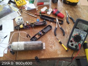
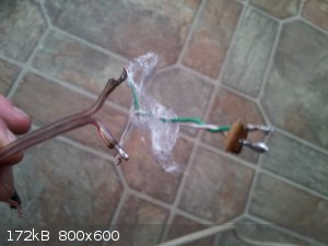
I hooked up the big 2kV, 24uF capacitor this morning to the bug zapper HV power supply. A 40 gauge copper bridge wire, about 1.5-2mm long was
connected at the other end of 12ft of RG6 coaxial cable. Wrapped around the bridge wire in a bit of plastic wrap was about 50mg of loose, crystalline,
ETN. The 24uF capacitor was only charged to 1600V because the bug zapper power supply took almost a full minute to even charge it up that much
(batteries are old, so replacing them could make a big difference). There was a huge bang when the wire was touched to the charged capacitor and on
inspection the plastic wrap was seen to be blown away and the bit of circuit board/spacer which held the bridge wire was broken away from the solder
joints.
Capacitor Energy = 1/2CV^2
Energy = 1/2*0.000024F*1600V^2
Energy = 30.7 Joules
If two were hooked in series and charged to 4000V:
Energy = 1/2*0.000012F*4000V^2
Energy = 96 Joules !!!
I am still just learning, but this amount of capacitance is likely way overkill even with a 40 gauge bridge wire, also, at least 4000V would be much
better than 2000V for long cable runs. It should be no problem initiating ETN through 100ft of cable with the right capacitor(s) and cable. I used a
half to a full foot of 18 gauge speaker wire on either end of the RG6 coaxial for this test, so a section of consumable wire of some sort could be
made as part of each EBW cap assembly with the idea that it would be consumed/destroyed in the blast.
I suppose three of these capacitors hooked in series, with appropriate bypass resistors, would have 8uF of capacitance and could be charged as high as
6000V which would be about right probably.
Energy = 1/2CV^2
Energy = 144J !!!
Remote Control of EBW Power Supply Charging and Firing
The big limitation to these systems is the transmission cable, which must be kept as short as possible for practical purposes. I see no reason why
heavy cables need to be run all the way back to the operator/shot firer. The power supply, capacitor(s) and firing switch/mechanism could all be
fairly close to the blast in a tough enclosure or even buried. Small signal, light gauge, wiring could be run to the distant operator/shot firer so
that charging and firing could be controlled as well as voltage/charge monitoring all from a distance. In fact if desired all that needs to be
relatively close to the blast is the capacitor(s) and the firing mechanism, the power supply could charge the capacitors through a fairly light copper
pair from a distance.
[Edited on 9-4-2015 by Hennig Brand]
"A risk-free world is a very dull world, one from which we are apt to learn little of consequence." -Geerat Vermeij
|
|
|
markx
National Hazard
   
Posts: 649
Registered: 7-8-2003
Location: Northern kingdom
Member Is Offline
Mood: Very Jolly
|
|
You need a beefier power supply for the cap. Using this bug zapper is like trying to fill a pool with a bucket 
E.g. a topology like this one:
http://www.hvlabs.hu/inverter/fcsinverter.gif
The IR2153 or 21531 are selfresonating drivers that can be tuned in on the sweet spot of the transformer and operated in halfbridge or push pull mode.
They are cheap and quite reliable, requiring very limited amount of external parts, but one has to limit the current through the chip Vcc leg to max
5mA. This can be done via a resistor of appropriate size if the supply voltage is fairly constant. With a battery though, I would suggest a sepic
converter for that job. It is very annoying when the circuit draws big amps from the battery dropping the voltage below the UVLO treshold of the
driver chip (9,5-10V) and the circuit starts to softswitch itself on and off. Then one tries to decrease the limiting resistor value and the chip
gives off the ghost when a fresh battery with higher voltage is connected...
A sepic converter will feed a stable voltage of appropriate value to power the chip independent of the input voltage from the battery and eliminates
the overcurrent problem very efficiently.
The output of the transformer can be driven through a simple voltage multiplier to get the required kV.
Exact science is a figment of imagination.......
|
|
|
Hennig Brand
International Hazard
    
Posts: 1284
Registered: 7-6-2009
Member Is Offline
Mood: No Mood
|
|
Thanks, not a bad idea. You know though, the two series connected bug zappers have no problem charging up 1.5uF to 2000V, from just a couple of 1.5V
AA cells, in well under 10 seconds. The last capacitor used really is a beast at 24uF and 2000V. Would be pretty funny to have an EBW power supply
made with eight or ten series/parallel connected bug zapper power supplies.  They are only $3-4 dollars each new IIRC and the first two were given to me broken so they were free. Pretty sure the transformers in them could
handle more current so I could probably crank them up some.
Here is a power supply I have used in the past that works great and is not picky at all about component choice (pretty much any transistors that can
handle the voltage and current within reason). I built a stun gun eight years ago or so and used the front half of one of these circuits when I built
it (up to and including T1). It made a simple and tough little HV supply.
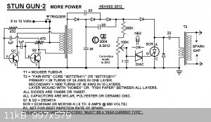
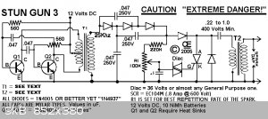
The circuits were taken from the following website which also has some assembly instructions.
http://chemelec.com/Projects/Stun-Gun-1/Stun-Gun.htm
I think it was probably the second one I used, but like I said before component choice is flexible. I wound my own transformers, or rewound I should
say T1 from a salvaged switching supply transformer. Some voltage multiplier stages after T1 and you have everything you need. What you suggested
could be a better solution, but it doesn't have to be too sophisticated and I kind of like working with garden variety discrete components such as
transistors, capacitors, resistors, etc.
[Edited on 9-4-2015 by Hennig Brand]
"A risk-free world is a very dull world, one from which we are apt to learn little of consequence." -Geerat Vermeij
|
|
|
markx
National Hazard
   
Posts: 649
Registered: 7-8-2003
Location: Northern kingdom
Member Is Offline
Mood: Very Jolly
|
|
I'm sure both options will work just fine....and usually whichever one is simpler will do a better job.
And then there are the days when simple stuff gets kinda out of hands   : :
![WP_20141112_005[1].jpg - 1.4MB](https://www.sciencemadness.org/whisper/files.php?pid=400492&aid=38877)
![WP_20141112_012[1].jpg - 1.3MB](https://www.sciencemadness.org/whisper/files.php?pid=400492&aid=38879) ![WP_20141112_007[1].jpg - 1.2MB](https://www.sciencemadness.org/whisper/files.php?pid=400492&aid=38881)
![WP_20141102_001[1].jpg - 1.4MB](https://www.sciencemadness.org/whisper/files.php?pid=400492&aid=38883)
Exact science is a figment of imagination.......
|
|
|
Hennig Brand
International Hazard
    
Posts: 1284
Registered: 7-6-2009
Member Is Offline
Mood: No Mood
|
|
Looks very nice. Is that an EBW power supply?
Also, forgot to mention that there were high ohmic value bleeder resistors across the original HV storage capacitors on the bug zappers' outputs.
These resistors as well as the original ca. 400V capacitors were removed so that the zapper supplies could be used to charge 1000V capacitors.
As was mentioned already, with two AA, 1.5 volt cells, the two series connected bug zapper power supplies took about a minute to charge the 24uF
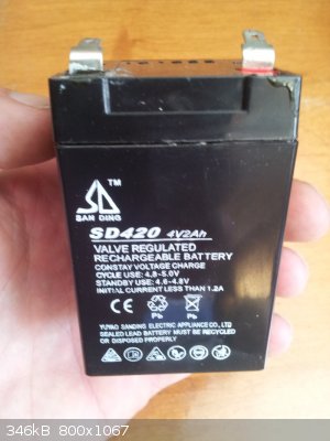
capacitor up to 1600V. The two AA batteries (3V total) were replaced with a small sealed lead acid battery (4V) which enabled the bug zapper supplies
to charge the 24uF capacitor up to the full 2000V in 30-40 seconds. I was just going to add more AA batteries in series/parallel to get higher
voltage/current capability, but this lead acid battery was sitting right on the table looking at me already. Components (transistors and transformers)
were monitored for excessive heating during charging and were found to get only slightly warm if at all. These bug zapper supplies could probably be
run from even higher supply voltages.
Almost like my brother knew what I needed when he dropped off the battery a couple of days ago which he said came out of a junked handheld spotlight
(like the ones used for jacking deer).
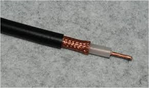
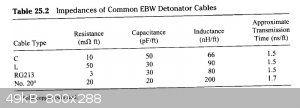
I have some RG-213 stored in a shed, but will have to dig it out to know for sure how much. It can be bought for $1/foot or less sometimes if you can
make a deal with some of the Ham radio nuts (have heard of it being sold sometimes for as little as 50 cents per foot). Here is a picture of RG-213.
It is a very heavy coaxial with 12.5 gauge center conductor I believe and very heavy braided shielding. According to the literature RG-213 is very
suitable for use as EBW transmission line. The table was taken from "Explosives Engineering", by Cooper.
[Edited on 10-4-2015 by Hennig Brand]
"A risk-free world is a very dull world, one from which we are apt to learn little of consequence." -Geerat Vermeij
|
|
|
Hennig Brand
International Hazard
    
Posts: 1284
Registered: 7-6-2009
Member Is Offline
Mood: No Mood
|
|
High Voltage/High Current Relay
This relay which I built in the last hour or two is extremely crude, but something much more refined could be easily built. Other than the foot long
piece of 1/2" brass rod purchased for $5 everything else was from the junk pile. The idea is that the capacitor(s) can be charged through the low
current normally closed contact (brass wood screw) and then once charged the solenoid could be activated which would dump the high current pulse
through the 1/2" brass contact and into the transmission line and bridge wire thereby initiating the cap. Of course the relay could also connect the
capacitor(s) to some other more efficient switching mechanism which could then dump the stored charge into the transmission line and bridge wire. The
relay can be operated remotely using a length of light gauge wire.
Here is a picture of the crude high voltage/ high current relay and also a tiny video of it in operation.
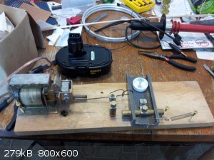
Attachment: Relay in Action.mp4 (9.2MB)
This file has been downloaded 1389 times
The solenoid is much bigger than it needs to be. It is rated for 120V and when kept mostly retracted it generates lots of force even when powered by
only an 18V cordless drill battery pack (as was done in the video). Also from reading some of the Tesla coil sites, it seems that contacts with large,
smooth surfaces with the right curvature can really reduce inductance and losses at a spark gap. I tried for 1" brass rod for contacts, but all I
could locate yesterday was 1/2".
The pivot screw has been replaced with a pivot bolt which looks a little less foolish and will work better and for longer too. The spring was also
positioned so that a little more tension was put on the contacts in the normally closed position. Picture below.
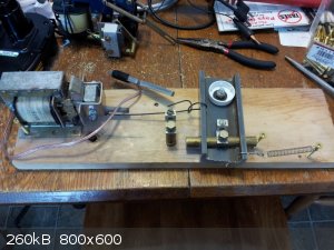
[Edited on 11-4-2015 by Hennig Brand]
"A risk-free world is a very dull world, one from which we are apt to learn little of consequence." -Geerat Vermeij
|
|
|
Hennig Brand
International Hazard
    
Posts: 1284
Registered: 7-6-2009
Member Is Offline
Mood: No Mood
|
|
Triggered Spark Gap Switch
From the little bit I have learned about it so far, trigatrons appears to be much more controllable, more reliable, faster and more efficient than
passive spark gaps (non-triggered spark gaps).
Here is a snip-it from the Wiki page on trigatrons:
"
A trigatron is a type of triggerable spark gap switch designed for high current and high voltage, (usually 10-100 kV and 20-100 kA,
though devices in the mega-ampere range exist as well). It has very simple construction and in many cases is the lowest cost high energy switching
option. It may operate in open air, it may be sealed, or it may be filled with a dielectric gas other than air or a liquid dielectric. The dielectric
gas may be pressurized, or a liquid dielectric (e.g. mineral oil) may be substituted to further extend the operating voltage. Trigatrons may be rated
for repeated use (over 10,000 switching cycles), or they may be single-shot, destroyed in a single use.
A trigatron has three electrodes. The heavy main electrodes are for the high current switching path, and a smaller third electrode serves as the
trigger. During normal operation, the voltage between the main electrodes is somewhat lower than the breakdown voltage corresponding to their distance
and the dielectric between them (usually air, argon-oxygen, nitrogen, hydrogen, or sulfur hexafluoride). To switch the device, a high voltage pulse is
delivered to the triggering electrode. This ionizes the medium between it and one of the main electrodes, creating a spark which shortens the
thickness of non-ionized medium between the electrodes. The triggering spark also generates ultraviolet light and free electrons in the main gap.
These lead to the rapid electrical breakdown of the main gap, culminating in a low resistance electric arc between the main electrodes. The arc will
continue to conduct until current flow drops sufficiently to extinguish it.
The triggering electrode is most often mounted through a hole in the center of the positive main electrode. The undrilled main electrode is the
negative electrode. When switching high currents, the electrodes undergo considerable heat stress, as they are directly involved in the electric arc.
This causes the surfaces to undergo gradual vaporization, so some designs incorporate methods to easily adjust the distance between the electrodes or
to actually replace the electrodes. The main electrodes are typically fabricated from brass, or alloys of copper and tungsten for longer electrode
life."
Found a good website with lots of technical data sheets for triggered spark gaps. Attached are a couple of related ones from the site.
http://www.reb3.com/
Attachment: Specifications for Spark-Gap Switches.pdf (951kB)
This file has been downloaded 2148 times
Attachment: Application Information for Spark-Gap Switches.pdf (326kB)
This file has been downloaded 2957 times
Here is a good DIY HV page with some simple firing circuits for trigatrons and where I found the link to the above commercial site:
http://hotstreamer.deanostoybox.com/ross/projects/Pulse/puls...
Here is a good electrical engineering journal article on trigatrons:
Attachment: Triggering in trigatron spark gaps - A fundamental study.pdf (1.8MB)
This file has been downloaded 1092 times
Threaded Switch Doesn't Bounce
The reason attention is being put on designing a triggered spark gap is because normal switches and relays have a variety of problems, such as switch
bounce, which can cause erratic behavior especially with such high currents and short pulse durations where perfect switching is vital to performance.
With the exception of not having timing as precise as with a trigatron, I think I may have a fairly simple solution for spark gap switching. One of
the electrodes could be fixed and the other could be set into an electrically insulated track and moved towards the other electrode until arc over
occurred firing the EBW. Timing would be awful compared to a trigatron, but how much does 1 or 2 seconds delay matter for general purpose blasting?
Unlike a true static spark gap, where firing voltage/charge is somewhat uncertain, the capacitor(s) could be charged up to the desired level with the
electrodes far enough apart to not result in premature firing and then when desired the movable electrode could be threaded into firing position.
[Edited on 13-4-2015 by Hennig Brand]
"A risk-free world is a very dull world, one from which we are apt to learn little of consequence." -Geerat Vermeij
|
|
|
nux vomica
Hazard to Others
  
Posts: 267
Registered: 18-7-2013
Member Is Offline
Mood: No Mood
|
|
Here's a link to a US co that manufactures ebw switches don't think you could buy off them but they have data sheets on line cheers nuxy.
http://www.highenergydevices.com/products/three-electrode%20...
|
|
|
jock88
National Hazard
   
Posts: 505
Registered: 13-12-2012
Member Is Offline
Mood: No Mood
|
|
Get Cooks book as it has lots of info.
Some reading on EBW's attached.
Attachment: ebw.rar (1.8MB)
This file has been downloaded 1071 times
|
|
|
Hennig Brand
International Hazard
    
Posts: 1284
Registered: 7-6-2009
Member Is Offline
Mood: No Mood
|
|
Screw Triggered Spark Gap
Thanks, that site looks interesting. There are also at least a few sites online with peoples' descriptions of how they have built their own. They
aren't terribly complicated and I probably will eventually build one.
Here are a couple pictures of the "Screw Gap". It works, but I have not tested it yet with proper transmission cable, proper EBW and explosives in a
cap.
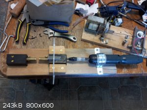 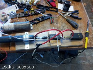
Thanks for the reading material Jock88.
edit:
Static Gap
A plain old static gap with a threaded adjustment for width would be the simplest thing, however, at these relatively low voltages the spark gap is
very narrow especially with large curved electrodes which are used because they are much more efficient than fine point contacts. A very narrow gap
and slight changes in the surface of the contacts (any kind of roughness or buildup) could make the gap fire early and wear or other changes could
cause the gap to fail to fire. Since energy is proportional to the capacitor(s) voltage squared the gap would need to be very carefully adjusted in
order to get good results.
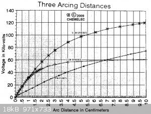
I used the calculator from the following site, which is apparently based on empirical data, to get data points for the attached graph which was made
in Excel. The other graph, showing higher voltages, came from the site linked to above regarding stun gun HV PS circuits.
https://www.cirris.com/learning-center/calculators/50-high-v...
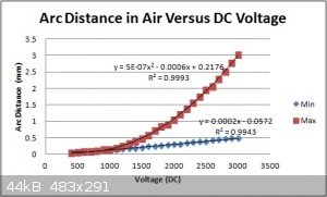 
Here is the same graph as above, but this time with extrapolated values from 3000-6000V.
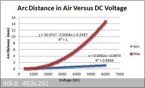
Ok, I just found the following appendix from the article, "Electrostatic Discharge: Understand, Simulate, and Fix ESD Problems, Third Edition
Published Online: 22 SEP 2009", which has tables giving break over voltages for spherical and pointed contacts. This looks like a decent reference.
Attachment: Spark Over Voltages (Wiley).pdf (429kB)
This file has been downloaded 1099 times
[Edited on 14-4-2015 by Hennig Brand]
"A risk-free world is a very dull world, one from which we are apt to learn little of consequence." -Geerat Vermeij
|
|
|
jock88
National Hazard
   
Posts: 505
Registered: 13-12-2012
Member Is Offline
Mood: No Mood
|
|
I wrongly give a book name above in my last post as Cook. That should be Cooper. There is a very useful chapter on EBW's.
Also the compressed .rar file in my last post needs to be decompressed and the starting point for reading the whole 'web page' is the file called
EBW_INFO.HTML
The attached file is from 'Twospoons' from this thread:
http://www.sciencemadness.org/talk/viewthread.php?tid=10874
May help in spark gap firing.
Jock88
Attachment: swinging cascade.pdf (59kB)
This file has been downloaded 791 times
[Edited on 14-4-2015 by jock88]
|
|
|
| Pages:
1
2
3
..
11 |