RogueRose
International Hazard

Posts: 1590
Registered: 16-6-2014
Member Is Offline
|
|
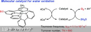
"New" catalyst splits CO2 & H2O with little energy.. What is this catalyst?
I came across this article and many references to it but the thing is I can't understand or decipher what the catalyst is, what it is made
of/composes it, etc. At the end of the article the "materials used" is listed and they seem "common" enough, but when it talks about the catalyst, I
don't understand how it is written:
[(tpy)(Mebim-py)RuII(S)]2+ (tpy = 2,2′ : 6′,2′′-terpyridine; Mebim-py = 3-methyl-1-pyridylbenzimidazol-2-ylidene; S = solvent)
CO2 & H2O catalyst
Here is what the article says:
Rising energy prices, diminishing reserves of petroleum, and environmental concerns are driving new thinking about our energy future. Given its
availability, with approximately 10,000 times the daily energy input required to meet current energy consumption, solar energy could be the ultimate
answer. However, solar energy is diffuse, spread over the earth’s surface, and requires vast collection areas for large-scale applications (1). A
more difficult challenge is the intermittency of the sun as an energy source. Meeting the challenge of providing power at night will require energy
storage on massive scales at levels exceeding the ability of existing or foreseeable energy storage technologies (2, 3). The only realistic
alternative is energy storage in chemical bonds and the increasingly popular concept of “solar fuels.” Solar fuels mimic natural photosynthesis in
using solar energy and artificial photosynthesis to convert readily available sources, water and carbon dioxide, into high-energy fuels. Target
reactions include water splitting into hydrogen and oxygen and reduction of carbon dioxide to carbon monoxide, other oxygenates, or hydrocarbons (Eqs.
1–3), as follows: Formula[1]Formula[2]Formula[3]
Carrying out these reactions presents a major challenge in chemical reactivity given their multiphoton, multielectron, multiatom character. It is
reassuring that similar hurdles have been overcome in natural photosynthesis, in which light-driven reduction of CO2 to carbohydrates by water occurs
(Eq. 4). However, photosynthesis in green plants took 2–3 billion years to evolve and utilizes a complex architecture that utilizes thousands and
thousands of atoms and multiple integrated assemblies (4, 5).Formula[4]
A simplifying factor, suggesting a mechanistic approach, comes with recognition that the target energy storage reactions can be split into constituent
“half reactions” which are shown for CO2 splitting in Eqs. 5 and 6. Photosynthesis in green plants occurs in the thylakoid membrane and uses
physically separated molecular assemblies for light-driven water oxidation (Photosystem II) and CO2 reduction (Photosystem I and the Calvin cycle) (6,
7). Electron/proton equilibration occurs by intra- or transmembrane electron/proton transfer channels driven by free energy gradients.
Application of a “half-reaction” strategy in artificial photosynthesis poses similar challenges. In both water oxidation and CO2 reduction,
mechanisms involving one-electron reactions are energetically untenable. They result in •OH on oxidation or Graphic on reduction at potentials too
high to be of interest in solar fuels half-reaction with E° = 2.72 V vs. NHE (E° is the standard electrode potential) for the •OH + H+ + e- →
H2O couple and E° = -1.90 V for the Graphic couple. By comparison, E° = 1.23 V for water oxidation to oxygen in Eq. 5 and E° = -0.12 V for CO2
reduction to CO in Eq. 6. The energy available in a 500-nm photon in the visible region of the solar spectrum is 2.48 eV. For the reaction, Graphic,
E° = -4.62 V (ΔG° = +4.62 eV) and, for the CO2 splitting reaction in Eq. 7, E° = -1.35 V (ΔG° = +2.70 eV). The CO product in Eq. 7 is of
interest as a component of syngas, a hydrogen/CO mixture for methanol synthesis (8, 9). Formula[5]Formula[6]Formula[7]
In order to carry out these reactions at or near the thermodynamic potentials for the separate half reactions requires catalysis and utilization of
multielectron, multiproton transfer catalysis. This, in turn, requires the accumulation of multiple redox equivalents at single chemical sites or
clusters and mechanistic pathways that avoid high-energy, 1e- intermediates. A key element in both is proton coupled electron transfer (PCET) and use
of half reactions in which both protons and electrons are lost or gained to avoid charge buildup. A second is electron-proton transfer (EPT), in which
concerted electron-proton transfer occurs to avoid high-energy intermediates (10⇓–12).
Impressive advances have been made in catalytic water oxidation by transition metal complexes at single-site catalysts
(13⇓⇓⇓⇓⇓⇓⇓⇓⇓⇓⇓–25). Progress has also been made on catalytic reduction of CO2 to CO (26⇓⇓⇓⇓⇓⇓⇓⇓⇓–36). Both
present a formidable challenge in chemical reactivity. Nonetheless, we report here that a single metal complex catalyst suffices for both half
reactions and apply it for electrocatalytic CO2 splitting.
Among the family of single-site Ru complex catalysts for water oxidation, [(tpy)(Mebim-py)RuII(S)]2+ 1 (tpy = 2,2′ : 6′,2′′-terpyridine;
Mebim-py = 3-methyl-1-pyridylbenzimidazol-2-ylidene; S = solvent. As [(tpy)(Mebim-py)RuII(OH2)]2+ in water) is a robust example. It undergoes water
oxidation by the mechanism shown in Scheme 1A (21, 25). In this mechanism, stepwise PCET oxidation and proton loss from Graphic provide access to RuV
= O3+. This high-oxidation state intermediate undergoes O-atom attack on water to give RuIII-OOH2+. Once formed, the peroxide intermediate undergoes
further oxidation and O2 loss and reenters the catalytic cycle as RuIII-OH2+. An important factor in the enhanced reactivity of the carbene complex
compared to related complexes comes from the favorable driving force for the O---O bond forming step (24, 25).
Scheme 1.
In this window
Download PPT
Scheme 1.
(A) Mechanism for electrocatalytic single-site water oxidation by 1 as [(tpy)(Mebim-py)RuII(OH2)]2+ in water (21, 25). (B) Mechanism for
electrocatalytic reduction of CO2 to CO by 1 as [(tpy)(Mebim-py)RuII(NCCH3)]2+ in CH3CN (36).
Electrocatalyzed reduction of CO2 by transition metal complexes, including polypyridyl complexes of Ru, is also well-known
(26⇓⇓⇓⇓⇓⇓⇓⇓⇓–36). Mechanistic insight has come from electrochemical and spectroscopic monitoring. A key element for polypyridyl
catalysts is initial polypyridyl-based reduction with the reduced ligands acting as electron reservoirs for subsequent CO2 reduction at the metal. For
example, in Scheme 1B (36), 1 (as [(tpy)(Mebim-py)RuII(NCCH3)]2+) is also a CO2 reduction catalyst in CH3CN. It undergoes two sequential 1e-
ligand-based reductions at Ep,c = -1.07 V and -1.33 V vs. NHE (Ep,c is the reductive peak potential) to give [(tpy-)(Mebim-py-)RuII(NCCH3)]0.
Ligand-based reduction is followed by rate limiting CO2 coordination, Graphic. Once the metallocarboxylate intermediate is formed, it undergoes
further reduction at the ligands to give CO and Graphic (Eq. 8) as final products (36). Formula[8]
Water oxidation and CO2 reduction by 1 in CH3CN-H2O mixtures were investigated. In the Ru(II) state, with 10% added CH3CN (vol/vol), in 0.1 M
NaH2PO4/Na2HPO4 buffer (pH 7.45), aqua substitution by acetonitrile, Graphic, occurs and was complete in 10 min. This was shown by spectrophotometric
monitoring, and the shift in λmax for the dominant metal-to-ligand charge transfer (MLCT) absorption from 456 nm to 420–440 nm (Fig. 1A). Cyclic
voltammetric (CV) measurements reinforce this observation. Addition of 10% CH3CN, in 0.1 M NaH2PO4/Na2HPO4 buffer (pH 7.45), causes the wave for
Graphic oxidation at Ep,a = 0.96 V vs. NHE (Ep,a is the oxidative peak potential) to diminish with appearance of a new wave at Ep,a = 1.30 V for
Graphic oxidation (Fig. 1B). The sense of the substitution is reversed upon oxidation. As shown in the Fig. 1B, Inset, in reverse scans, a distorted
wave for Graphic reduction appears at Ep,c = 0.80 V rather than a wave for Graphic reduction. The reactions that occur in this sequence are shown in
Eqs. 9–11. Re-aquation at Ru(III) allows the catalyst to enter the catalytic cycle in Scheme 1A as RuIII-OH2+ and water oxidation to proceed without
interference from substitution.
Fig. 1.
In this window
Download PPT
Fig. 1.
(A) UV–visible spectra of 50 μM 1 in 0.1 M NaH2PO4/Na2HPO4 buffer (pH 7.45) with increasing amounts of added CH3CN. (B) CVs of 1 mM 1 in 0.1 M
NaH2PO4/Na2HPO4 buffer (pH 7.45) with increasing amounts of added CH3CN. Electrode, glassy carbon (0.071 cm2); scan rate, 100 mV/s. (Inset) Comparison
of CVs with 0% (black) and 10% (magenta) added CH3CN with potential scan reversal before water oxidation wave. The reference electrode used was the
saturated calomel electrode (SCE) (0.244 V vs. NHE) with reported potentials converted to NHE. In A and B, the UV-visible and CV measurements were
conducted after addition of CH3CN for 10 min. (C) As in B, controlled potential electrolysis in the absence (red) or presence (blue) of 1 mM 1 with
10% added CH3CN. Electrode, BDD|Si (approximately 0.85 cm2); applied potential, 1.55 V vs. NHE. The solution was stirred during electrolysis. (D) As
in C, showing corresponding gas chromatograms (thermal-conductivity detector, TCD) in the absence (red) or presence (blue) of catalyst after
electrolysis. The black line represents the gas chromatogram before electrolysis. The chromatography response for O2 was normalized to O2/N2 in air.
In the cycle in Scheme 1A, water oxidation is triggered by oxidation of RuIV = O2+ to RuV = O3+ at an onset potential of approximately 1.4 V vs. NHE.
Fig. 1C shows the results of a controlled potential electrolysis experiment at 1.55 V with 10% added CH3CN at a polycrystalline silicon wafer coated
with boron-doped diamond (BDD|Si). Electrode choice is important in these experiments with competitive surface oxidation occurring at conventional
glassy carbon or other carbon electrodes. The catalytic current decreased initially, but was relatively stable over the 3 h electrolysis period. The
current decrease appears to be due to slow catalyst decomposition by oxidation of the carbene ligand.* Analysis of the head space in the electrolysis
cell by gas chromatography (Varian 450-GC) demonstrated oxygen production with a Faradaic efficiency of approximately 88% through approximately 5
catalyst turnovers (Fig. 1D). Formula[9]Formula[10]Formula[11]
Fig. 2A shows CVs of 1 atm CO2-saturated solutions containing 1 mM 1 in 0.1 M Graphic (Graphic) at a glassy carbon electrode with addition of
increasing amounts of water. Peak currents for electrocatalytic CO2 reduction decreased slightly with added water falling by 20% with 5% added water.
Fig. 2B shows the results of a controlled potential electrolysis experiment at -1.45 V vs. NHE at a glassy carbon in a CO2 saturated solution with 5%
added water. The catalytic current was sustained for at least 3 h with a slow current decrease due to catalyst precipitation on the electrode
surface.† The catalyst retained its activity as shown by CV measurements at fresh electrodes (Fig. 2C). Analysis of the head space in the
electrolysis cell by gas chromatography showed formation of CO with a Faradaic efficiency of approximately 85% with 3.5 catalyst turnovers (Fig. 2D).
A small amount of hydrogen was also detected in the head space with a Faradaic efficiency of < 2% (Fig. 2D, Inset). There was no evidence for
CH3OH, HC(O)H, or HC(O)O- in the liquid phase by gas chromatography (GC-2014, Shimadzu) and 1H NMR (Bruker Avance-400 MHz). The reaction stoichiometry
for the half reaction with added water is shown in Eq. 12 (36), as follows:Formula[12]
Fig. 2.
In this window
Download PPT
Fig. 2.
(A) CVs of 1 mM 1 in 0.1 M Graphic under CO2 with increasing amounts of added water. Electrode, glassy carbon (0.071 cm2); scan rate, 100 mV/s.
(Inset) As in the figure but under Ar. The reference electrode used was Ag/AgNO3 (0.55 V vs. NHE) with reported potentials converted to NHE. (B) As in
A, controlled potential electrolysis with 5% added water under Ar (red) and CO2 (blue). Electrode, glassy carbon (0.071 cm2); applied potential, -1.45
V vs. NHE. The solution was stirred during electrolysis. (C) As in B, CVs before (red) and after (blue) electrolysis under CO2 at freshly polished
glassy carbon electrodes. (D) As in B, showing corresponding gas chromatograms (pulsed discharge helium ionization detector, PDHID) in the absence
(red) or presence (blue) of catalyst after electrolysis. The black line represents the gas chromatogram before electrolysis.
The ability of the single-site Ru carbene complex to act as an electrocatalyst for both water oxidation and CO2 reduction provides a basis for the two
compartment electrolysis cell for CO2 splitting shown in Fig. 3. In the cell a Nafion cation exchange membrane cast on a glass frit (Nafion|Frit) was
used to separate the compartments (37).‡
Fig. 3.
In this window
Download PPT
Fig. 3.
Schematic diagram for the two-compartment, Nafion|Frit-separated electrochemical cell for CO2 splitting. A three-electrode potentiostat was used to
control the two-electrode cell with one electrode as the working electrode and the other acting as both counter and reference electrodes. The iR drop
across the Nafion|Frit was not compensated.
The i-E characteristics of the two-electrode electrochemical cell were examined by CV measurements (Fig. 4). In these experiments, the anode
compartment contained the aqueous NaH2PO4/Na2HPO4 buffer (pH 7.45) with 10% added CH3CN and the cathode 0.1 M Graphic in CO2-saturated CH3CN with 5%
added H2O. The potential applied at the working electrode was monitored by a second potentiostat (Figs. S1 and S2). Assignment of the
current-potential features in Fig. 4 are based on comparisons with profiles for the separate catalytic water oxidation and CO2 reduction
half-reactions described here and previously (25, 36).
Fig. 4.
In this window
Download PPT
Fig. 4.
Note and . Blue lines: CVs at glassy carbon electrodes (0.071 cm2) with 10% CH3CN and 5% H2O added in the anode and cathode compartments,
respectively: (A), anodic scan for water oxidation and (B), cathodic scan for CO2 reduction. The dashed blue lines are the background without
catalyst. Red lines: the applied potential (vs. NHE) at the working electrode during forward potential scans. As examples, the peak potentials for
peaks a1 and b1, as determined by the intersecting red dashed lines, are shown in the figure. Scan rate, 100 mV/s.
In the current-potential traces, i-E features appear from +2.2 to +3.25 V in Fig. 4A and from -2.2 to -3.25 V in Fig. 4B. The former are associated
with the metal-based oxidations which result in water oxidation in Scheme 1A, and the latter to the ligand-based reductions for electrocatalytic CO2
reduction in Scheme 1B. As dictated by the potentials for RuIV = O2+ → RuV = O3+ oxidation at approximately +1.55 V for peak a3 in Fig. 4A, which
triggers water oxidation to O2, and Graphic reduction at approximately -1.45 V for peak b3 in Fig. 4B, which triggers CO2 reduction to CO, CO2
splitting in Eq. 7, occurs at an applied cell potential of approximately 3.0 V [= +1.55 - (-1.45)], with an overpotential of approximately 1.65 V (=
3.0 - 1.35). The current densities of both anodic and cathodic scans in Fig. 4 are equivalent with overall cell performance limited by the rate of
water oxidation at the anode as was determined by the separate studies on the half reactions in Figs. 1 and 2.
Fig. 5 shows a current-time (i-t) profile obtained by controlled potential electrolysis (3.0 V) under the conditions in Fig. 3 with two BDD|Si
electrodes (approximately 0.85 cm2). The physically separated gaseous products were collected in the head spaces of the separate electrode
compartments for gas chromatographic analysis.
Fig. 5.
In this window
Download PPT
Fig. 5.
Blue line: As in Fig. 3, controlled potential electrolysis at 3.0 V at two BDD|Si electrodes (approximately 0.85 cm2). Red line: Background current
without added catalyst. The solution was unstirred during the electrolysis to minimize solution equilibration between cell compartments.
Based on the integrated i-t profiles in Fig. 5 and gas chromatographic analyses, coulombic efficiencies for formation of approximately 7.4 μmol of CO
(approximately 5 TONs), approximately 0.5 μmol of H2 (approximately 0.3 TONs), and approximately 2.9 μmol of O2 (approximately 2 TONs) for a 3 h
electrolysis period were approximately 76, 5, and 60%, respectively. CO and O2 have a ratio of 2.5∶1, close to the 2∶1 expected for CO2 splitting.
For comparison, electrolysis under identical conditions but without catalyst resulted in < 5% gaseous products.
The results described here illustrate the use of a single catalyst for CO2 splitting, but this is only a first step. Under our conditions,
electrocatalysis is limited by the rate of water oxidation at the anode. Long-term performance is further limited by slow carbene ligand oxidation at
the anode* and catalyst precipitation at the cathode.† More efficient designs, based on ligand variations and surface attachment, are currently
under investigation.
In its simplicity, the contrast with natural photosynthesis is striking. Photosynthesis in green plants involves thousands of atoms, five
membrane-bound integrated assemblies, and the Calvin cycle and evolved over billions of years to achieve CO2 splitting into oxygen and carbohydrates.
In the electrochemical/photoelectrochemical approach, single catalysts or pairs of catalysts are combined with semiconductors, electrodes, wires, and
membranes to connect the half reactions and exchange electrons and protons.
Previous Section
Next Section
Materials and Methods
Chemicals.
NaH2PO4 (≥99.5%), Na2HPO4 (≥99.5%), and tetrabutylammonium hexafluorophosphate (Graphic) was obtained from Fluka. CO2 gas was purchased from
Airgas National Welders (medical grade, 99.999%). All other reagents were ACS grade and used as received. All aqueous solutions were prepared with
Milli-Q ultrapure water (> 18 MΩ), and all nonaqueous solutions were prepared with acetonitrile (CH3CN) of HPLC grade unless stated otherwise.
Instrumentation.
Electrochemical measurements were performed with the model CHI660D electrochemical workstation. The three-electrode system for half-reaction study
consisted of a working electrode, a platinum wire counter electrode, and a saturated calomel electrode (SCE) reference electrode (approximately 0.244
V vs. NHE) in aqueous solution or an Ag/AgNO3 reference electrode (approximately 0.55 V vs. NHE) in nonaqueous solution. The two-electrode system for
CO2 splitting consisted of electrodes of the same materials, with one as the working electrode and the other acting as both counter and reference
electrodes. In the two-electrode system, a second potentiostat was integrated to monitor the real potential applied at the working electrode by
including an additional counter (Pt wire) and reference (SCE for aqueous solution or Ag/AgNO3 for nonaqueous solution) electrodes to constitute a
three-electrode system. Unless stated otherwise, all potentials were reported vs. NHE.
The gas product analysis in the headspace was conducted by gas chromatography (Varian 450-GC, molecular sieve column) with thermal-conductivity
detector (TCD) for the detection of O2 in the anode compartment and pulsed discharge helium ionization detector (PDHID) for the detection of CO and H2
in the cathode compartment. Calibration curves for O2, CO, and H2 were determined separately. HC(O)H or CH3OH as possible products in the liquid phase
were analyzed by gas chromatography with flame ionization detector (FID) (Shimadzu GC-2014, Agilent DB-Wax column) and HC(O)O- by 1H NMR (Bruker
Avance-400 MHz). For the latter, 30–50% CD3CN was added to the electrolyzed solution prior to NMR measurement. All experiments were performed at
room temperature 22 °C.
Synthesis.
Synthesis of catalyst 1 was reported elsewhere (38). Briefly, it was obtained by reaction of the monocationic carbene precursor ligand with Ru(tpy)Cl3
in ethylene glycol at 150 °C in the presence of NEt3. In this case, the aqua complex is the product rather than the chloro analog due to the
trans-labilizing effect of the carbene.
Other Procedures.
Prior to the experiments, the glassy carbon disk electrode (0.071 cm2) was polished with 0.05 μm Al2O3 slurry to obtain a mirror surface followed by
sonication in distilled water for 30 s to remove debris, and were thoroughly rinsed with Milli-Q ultrapure water.
The BDD|Si electrode (approximately 0.85 cm2) was fabricated by depositing boron-doped diamond films on polycrystalline silicon wafers by microwave
plasma-enhanced chemical vapor deposition (MPCVD). The MPCVD was performed in a 915 MHz plasma at a growth pressure of approximately 80 Torr. A 3%
methane/hydrogen source gas, doped with 100 ppm of diborane, was used during deposition at a temperature of approximately 800 °C. The films were
approximately 1.56 microns in thickness, with a sheet resistance of approximately 110 Ω/sq. The BDD|Si electrode was used for electrolysis without
further treatment.
The glass frit-supported Nafion film (Nafion|Frit) was prepared by carefully spreading 40 μL of 2 wt % Nafion perfluorinated ion-exchange resin
solution (diluted by methyl alcohol) onto the frit surface on the anode side (Fig. 3), followed by drying at room temperature.
|
|
|
violet sin
International Hazard
Posts: 1477
Registered: 2-9-2012
Location: Daydreaming of uraninite...
Member Is Offline
Mood: Good
|
|
Looks pretty straight forward, no offence meant. It surely looks like gibberish if you havent looked up one of these fancy new fangled substances in
a while. Interesting how they now use sooo much more info to get the catalysts just so. Size, electron distribution, shape, specific high/low charge
pockets around active part... What wild stuff these days. For the record, I know shite about these. Just that few papers lead me to similar
jumbles and I was dissapointed, way way way out of my ability.
[(tpy)(Mebim-py)RuII(S)]2+ (tpy = 2,2′ : 6′,2′′-terpyridine; Mebim-py = 3-methyl-1-pyridylbenzimidazol-2-ylidene; S = solvent)
Typ = 2,2' : 6',2" terpyridine
Mebin-py = 3-methyl-1-pyridylbenzimidazol-2-ylidene
S = solvent
Rn II = Ru(2+) pretty sure?
(Just strung together from above)
2,2'-terpyridine-3-methyl-1-pyridylbenzimidazol-2-ylidene with Ruthenium in 'er.
Then did a google search on the jumble, got something like this, but it wasn't a direct match.
[Edited on 30-12-2016 by violet sin]
[Edited on 30-12-2016 by violet sin]
|
|
|
RogueRose
International Hazard
Posts: 1590
Registered: 16-6-2014
Member Is Offline
|
|
Quote: Originally posted by violet sin  | Looks pretty straight forward, no offence meant. It surely looks like gibberish if you havent looked up one of these fancy new fangled substances in
a while. Interesting how they now use sooo much more info to get the catalysts just so. Size, electron distribution, shape, specific high/low charge
pockets around active part... What wild stuff these days. For the record, I know shite about these. Just that few papers lead me to similar
jumbles and I was dissapointed, way way way out of my ability.
[(tpy)(Mebim-py)RuII(S)]2+ (tpy = 2,2′ : 6′,2′′-terpyridine; Mebim-py = 3-methyl-1-pyridylbenzimidazol-2-ylidene; S = solvent)
Typ = 2,2' : 6',2" terpyridine
Mebin-py = 3-methyl-1-pyridylbenzimidazol-2-ylidene
S = solvent
Rn II = Ru(2+) pretty sure?
(Just strung together from above)
2,2'-terpyridine-3-methyl-1-pyridylbenzimidazol-2-ylidene with Ruthenium in 'er.
Then did a google search on the jumble, got something like this, but it wasn't a direct match.
[Edited on 30-12-2016 by violet sin]
[Edited on 30-12-2016 by violet sin] |
Thanks for clearing that up! I was looking at it in a different way, kinda dislexic like I guess, so it was really difficult for me to make heads or
tails of it.
I figured it was pretty far out of home chem range but I thought it was worth looking at.
|
|
|
DDTea
National Hazard
Posts: 940
Registered: 25-2-2003
Location: Freedomland
Member Is Offline
Mood: Degenerate
|
|
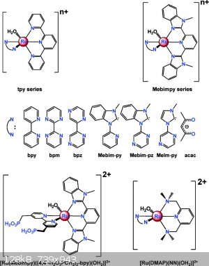
There is a lot of gobbledy-gook jargon here for the newcomer to the field. The catalyst and Mebim-py ligand are shown in the attached diagram (copied
from J.J. Concepcion, J.W. Jurss, M.R. Norris, Z.Chen, J.L. Templeton and T.J. Meyer* Inorg. Chem., 2010, 49 (4), pp 1277–1279 ) and also in Fig. 3
in the present paper.
| Quote: | | . Interesting how they now use sooo much more info to get the catalysts just so. Size, electron distribution, shape, specific high/low charge pockets
around active part... What wild stuff these days. |
Isn't it? I recall someone saying that physical organic chemistry is a dying field. Someone else corrected him: it isn't dying, it has become
commonplace. Researchers understand that they must keep the techniques of physical organic chemistry in the back of their minds if they ever hope to
optimize reactions or design catalysts on the basis of anything besides luck. But it isn't quite as precise as you may think. After all, it's rarely
possible to isolate and modulate a single variable at a time with organometallic complexes. At the same time, it's important to try to develop a
sense of how structure relates to reactivity (within certain limits). It can't be emphasized enough that, "two things that look different probably
are," and that the temptation to look for general rules is a trap.
[Edited on 1-3-17 by DDTea]
[Edited on 1-4-17 by DDTea]
"In the end the proud scientist or philosopher who cannot be bothered to make his thought accessible has no choice but to retire to the heights in
which dwell the Great Misunderstood and the Great Ignored, there to rail in Olympic superiority at the folly of mankind." - Reginald Kapp.
|
|
|
|