Sciencemadness Discussion Board

PC PSU to laboratory PSU

 Pages:  1    3

Organikum - 11-5-2005 at 04:51

Look here

Hey! Thats a good one isnĀ“t it?

/ORG

[Edited on 22-1-2007 by vulture]

Rosco Bodine - 12-12-2006 at 09:44

Good idea ........

However , it's only a start towards a true Lab Power Supply
since it doesn't allow for any incremental control of the
voltage or current .

I have been trying to find a way to provide those controls .
The attached circuit is what the effort at designing something
has produced . The design is the product of what has been my interpretation of the parameters in discussions with 12AX7 and Twospoons . It is only a theoretical model at
this point and has not been built or tested , so it remains
something of a work in progress , but hopefully near completion . The schematic I am attaching here because
this seems to be the most pertinent thread where any searches may locate it .

This schematic is like I said a work in progress and a
few changes will be made before it is complete .
A couple of errors have been found already , a typo
of sorts that I need to correct concerning the inputs
on U1 and U2 which are flipped , and should have the same orientation as the other four . And there are a couple of
other things I have caught proofreading the schematic .
So check back as there will be some minor changes ,
and corrections made as this design is completed .

The corrected schematic with regards to U1 and U2 is attached . A few other changes are planned yet .


[Edited on 14-12-2006 by Rosco Bodine]

Attachment: Converter for 550W ATX Computer Power Supply to 50A Laboratory Power Supply.pdf (52kB)
This file has been downloaded 1986 times


The_Davster - 12-12-2006 at 09:52

Yeah, that link is the design I based this:
https://sciencemadness.org/talk/viewthread.php?action=attach...
and more recently this:
https://sciencemadness.org/talk/viewthread.php?action=attach...
off of. Works great. Only reason I had to buid a new one is my older ones contact points rusted very badly. And I killed a few wires pulling >15A through only 2 16 or 18 gauge wires.

[Edited on 12-12-2006 by The_Davster]

Rosco Bodine - 12-12-2006 at 10:40

Yeah it has certainly been a motivator to make use
of a PC power supply if possible , once you check the
prices on manufactured power supplies having similar
current capability . Even if I had that kind of money
I would sure rather spend it on something else , if
an acceptable substitute could be improvised for
less than a tenth what the conventional model costs .
It can be fun to try to " beat the system " with a bit
of ingenuity and improvisation :D

Somebody please send that fellow who posted that other page a link to this thread and/or the attached schematic . People who are actively building and
prototyping will likely get to this a long time before
I do ....if I ever get to such things anymore . I'm
getting old and slower by the day sort of like an old
clock winding down . So any of you younger folks
that may have any use for any of this stuff , just
go ahead and make use of it .

jpsmith123 - 12-12-2006 at 18:16

Unless you want to do it as a hobby, why bother trying to build a variable, high-current lab power supply, when you can buy one, new, rather cheaply, on Ebay?

While the cost for most of the electronic parts may be relatively cheap, the hardware costs, e.g., case, panel meters, fan, heatsinks, etc. can add up fast.

I built one several years ago, and I ended up spending more money than I would have for a good used (and for certain brands, new) supply.

Then there's the factors of time and effort; by the time you come up with a design, and then etch, drill, and populate a board; prepare the case, wire it, debug it, etc. (and assuming your design is reasonable in the first place), you're probably talking about several days of labor.

On the other hand, you can get a new Mastech 30V 20A general purpose (switching type) lab power supply for $200.00 on ebay.

For a little more money, you can get 50V 20A or 30V 30A units.

I just got the HY3020E, and although it's no Hewlett Packard or Sorenson, so far it seems hard to beat at a price of $200.00.

Rosco Bodine - 12-12-2006 at 19:57

Quote:
Originally posted by jpsmith123
Unless you want to do it as a hobby, why bother trying to build a variable, high-current lab power supply, when you can buy one, new, rather cheaply, on Ebay?


Because you can build something having more than twice the
current at the lower voltage you need for a quarter to a third
the cost ......could be one reason .

Quote:

While the cost for most of the electronic parts may be relatively cheap, the hardware costs, e.g., case, panel meters, fan, heatsinks, etc. can add up fast.


Depends on what you can scrounge or what you may
have on hand .

Quote:

I built one several years ago, and I ended up spending more money than I would have for a good used (and for certain brands, new) supply.


What type of power supply was it , what current rating ,
and what sort of range and type of controls did it have ?

Quote:

Then there's the factors of time and effort; by the time you come up with a design, and then etch, drill, and populate a board; prepare the case, wire it, debug it, etc. (and assuming your design is reasonable in the first place), you're probably talking about several days of labor.


I wouldn't even bother to etch a board for something
like this . I'd stick the components on perfboard and
bend the excess lead wires into point to point traces
on the underside using bare wire to fill the gaps
and using jumpers of connection wire where needed there and also topside . Assembly time is more like
hours on something like this , not days .

Quote:

On the other hand, you can get a new Mastech 30V 20A general purpose (switching type) lab power supply for $200.00 on ebay.

For a little more money, you can get 50V 20A or 30V 30A units.

I just got the HY3020E, and although it's no Hewlett Packard or Sorenson, so far it seems hard to beat at a price of $200.00.


For anybody who wants to spend $200 on a 20 Amp supply , that's their privilege ....I won't . And when it gets to higher currents the price goes up substantially .

Actually I watched the auctions on eBay regularly for
awhile and sometimes there are what looked to be some decent bargains , although to me that isn't one of them .
It's like " where's the beef " :D What is the price for a
40 A unit ? Maybe send a copy of my file to Mastech
and ask 'em what they want for a 50 A unit . They really ought to love that .

One advantage of a converter is that the ATX power module can be replaced pretty cheaply if and when it expires . You can buy another one and just plug it in .

The current capacity is also there right where it is needed
in the lower voltages used for electrolysis .

And probably there is indeed the " hobby " factor
involved in something like this ....which if you build
it , you know what is in it and you make it the way you want it . It is sort of like a RC airplane I guess .....
you can pay somebody to build 'em for you I suppose ,
or you could just build it yourself .

Natures Natrium - 13-12-2006 at 13:04

Damn, those are some really cool designs you guys have come up with. Something like that is exactly what I need for my project, but when I opened up the schematic I sounded like a backwoods red-neck trying to read chinese. "Durr, whats all the funny squiggly lines for?"

Although I dont see myself attempting this anytime in the near future, I did have a question about it: How do you adjust the voltage/ampreage on the schematic posted?

-NN

Rosco Bodine - 13-12-2006 at 14:33

Quote:
Originally posted by Natures Natrium
Damn, those are some really cool designs you guys have come up with.


Thanks . I think they are pretty cool too . Even cooler if they work well in reality like they are supposed to work in theory and on paper . You don't really know for sure until you throw the switch:D Then comes the moment of truth .

Quote:

Something like that is exactly what I need for my project, but when I opened up the schematic I sounded like a backwoods red-neck trying to read chinese. "Durr, whats all the funny squiggly lines for?"


Those are symbols for resistors . They are little cylinders
of carbon mixed with various amounts of ceramic so that
they have measured value of resistance to electrical current ,
as if they were wire filaments of a certain length and diameter ....smaller giving greater resistance and larger giving lower resistance . They are something like tiny heating elements having different ratings . The small ones which
most of these are , are about the size of a single grain of rice having a wire about the size and length of a straight pin
coming out each end .

The triangle shaped symbols are amplifiers .

Quote:

Although I dont see myself attempting this anytime in the near future, I did have a question about it: How do you adjust the voltage/ampreage on the schematic posted?

-NN


Look down at the bottom left quadrant .

The two " front panel controls " are like volume knobs ,
you just rotate 'em clockwise to turn up the power
and watch the meters to set it where you want .

You see that little arrow that points against the resistor ,
is a sliding contact , or " wiper " in the control pot that
makes contact at different points along the length of
the resistor inside , and that gives a voltage that varies
accordingly , and changes the signal to the amplifiers ,
which then changes the output .

[Edited on 13-12-2006 by Rosco Bodine]

12AX7 - 13-12-2006 at 15:07

Quote:
Originally posted by Natures Natrium
Although I dont see myself attempting this anytime in the near future, I did have a question about it: How do you adjust the voltage/ampreage on the schematic posted?


Unfortunately, you can't. Rosco completely botched the feedback loop, so you aren't going to get a constant voltage output at the very least. If it doesn't explode or oscillate under a variety of conditions first.

Tim

Maya - 13-12-2006 at 15:14

New to this thread but what I basically pick up w/o reading everything is low variable voltage supply: why not go old school like I always made my supplies?

Variable Transformer + 4 diodes + some large capacitors? Inductors and resistors optional.....

Rosco Bodine - 13-12-2006 at 15:24

Quote:
Originally posted by 12AX7
Quote:
Originally posted by Natures Natrium
Although I dont see myself attempting this anytime in the near future, I did have a question about it: How do you adjust the voltage/ampreage on the schematic posted?


Unfortunately, you can't. Rosco completely botched the feedback loop, so you aren't going to get a constant voltage output at the very least. If it doesn't explode or oscillate under a variety of conditions first.

Tim


The component numbers and paths are right there for
your specificity in describing where *exactly* you see a problem . So which one of the feedback loops are you
seeing as a problem ....the output stage I presume ,
since all the others are textbook models ? Actually
I think the output stage is a textbook model too ,
it's just probably not in a book you have read yet .

You want to chug back on over to whimsy and sort it
out ....or right here would be fine too .

Natures Natrium - 13-12-2006 at 15:27

Well, honestly, I knew those were resistors. I was just trying to convey in a humorous way how I found the total diagram to be overwhelming on first sight. The only circuit I have ever built is the flyback driver (powerlabs design, for use in generating ozone). I did not know however that those triangles were amplifiers. I have heard of mosfets, and I recognize the two flat parallel lines as capicitors, but what does it mean when one of the lines is paranthesis shaped (ie "--|(--" )?

Hmm, either way I would not want to even attempt it until someone else had verified it as a working design, I know too little and it would take far too much time. I suppose for someone like me, spending the money on a commercial unit might makes sense. Even if I spent $200 on a PS, combined with my costs so far, it would still be half the price of a more expense unit and probably put out twice as much O3.

But, I digress from the topic.

-NN

PS Maya, do you have plans for this thing? I very much like simple, and I only need 24V @ ~5-8A.

Rosco Bodine - 13-12-2006 at 15:30

Quote:
Originally posted by Maya
New to this thread but what I basically pick up w/o reading everything is low variable voltage supply: why not go old school like I always made my supplies?

Variable Transformer + 4 diodes + some large capacitors? Inductors and resistors optional.....


Maya , that's perfectly fine for supplies that are maybe
30 Amps or less .....but we are looking at power supplies for
electrochemistry that are in the >30A range , where
straight linear supplies are very bulky and inefficient ,
as well as hugely expensive .

jpsmith123 - 13-12-2006 at 15:36

Quote:

Unless you want to do it as a hobby, why bother trying to build a variable, high-current lab power supply, when you can buy one, new, rather cheaply, on Ebay?


Quote:

Because you can build something having more than twice the
current at the lower voltage you need for a quarter to a third
the cost ......could be one reason .


I would say the relative "cost" is still debatable at this point.

In any case, from your earlier statements, you seemed to imply that you saw the project as a general purpose lab supply that others might be interested in building, accordingly. For what application do you anticipate needing such a high current, regulated, low voltage supply?

Quote:

While the cost for most of the electronic parts may be relatively cheap, the hardware costs, e.g., case, panel meters, fan, heatsinks, etc. can add up fast.


Quote:

Depends on what you can scrounge or what you may
have on hand .


Well, yes, and if you don't have it on hand, you're looking at spending some potentially serious money.

Quote:

I built one several years ago, and I ended up spending more money than I would have for a good used (and for certain brands, new) supply.


Quote:

What type of power supply was it , what current rating ,
and what sort of range and type of controls did it have ?


It was a 0 to 120 volt DC, 10 amp, switching supply with variable current limiting, in a nice anodized aluminum case, with fairly high quality analog panel meters, and fairly high quality 10 turn potentiometers.

Between the case, meters, heatsink, fan, switches, pots, and miscellaneous hardware, I had about $200.00 into it as I recall. I probably had at least another $100.00 invested in the electronic parts.

Quote:

Then there's the factors of time and effort; by the time you come up with a design, and then etch, drill, and populate a board; prepare the case, wire it, debug it, etc. (and assuming your design is reasonable in the first place), you're probably talking about several days of labor.


Quote:

I wouldn't even bother to etch a board for something
like this . I'd stick the components on perfboard and
bend the excess lead wires into point to point traces
on the underside using bare wire to fill the gaps
and using jumpers of connection wire where needed there and also topside . Assembly time is more like
hours on something like this , not days .


Trying to do that with a circuit like the one you've posted would be a sloppy mess and a major PITA, IMO. Especially if you end up having to fool around with it and make some component changes to get it working to your satisfaction.

In any case, even if your design is good as is, and your "circuit board" comes together the first time with no mistakes, just mounting heat sinks and fans, drilling and punching holes for meters, switches, LEDs, wiring, etc., generally takes much more than "hours". Hell, just figuring out the layout of the parts in the enclosure, or rummaging through online catalogs for necessary parts, can take hours.

I've built enough gadgets to know it almost never takes merely "a few hours".

Quote:

On the other hand, you can get a new Mastech 30V 20A general purpose (switching type) lab power supply for $200.00 on ebay.

For a little more money, you can get 50V 20A or 30V 30A units.

I just got the HY3020E, and although it's no Hewlett Packard or Sorenson, so far it seems hard to beat at a price of $200.00.


Quote:

For anybody who wants to spend $200 on a 20 Amp supply , that's their privilege ....I won't .


You almost certainly will, if your time has any value at all. In fact, how much time have you spent on it already? Don't tell me you haven't already spent a few hours.

Quote:

And when it gets to higher currents the price goes up substantially .


The price is generally more a function of power throughput than current. The 30 amp Mastech is capable of 0 to 30 volts, and you'll pay about $50.00 more for that extra 300 watts.

Quote:

Actually I watched the auctions on eBay regularly for
awhile and sometimes there are what looked to be some decent bargains , although to me that isn't one of them .
It's like " where's the beef " :D What is the price for a
40 A unit ? Maybe send a copy of my file to Mastech
and ask 'em what they want for a 50 A unit . They really ought to love that .


Well, look up the prices of some similarly rated U.S. made power supplies, if you don't think $200.00 is a bargain.

Quote:

One advantage of a converter is that the ATX power module can be replaced pretty cheaply if and when it expires . You can buy another one and just plug it in .


Perhaps; but IIRC, I've never seen one go bad during normal usage, so unless you abuse it, I can't see too much of an advantage there.

Quote:

The current capacity is also there right where it is needed
in the lower voltages used for electrolysis .


Electrolysis at 40 or 50 amps implies a big cell, and if you're trying to make chlorates or perchlorates using MMO or platinized anodes, a very costly cell. Regardless, why not just directly use the 5V output and adjust the electrodes for the current you want to run?

Quote:

And probably there is indeed the " hobby " factor
involved in something like this ....which if you build
it , you know what is in it and you make it the way you want it . It is sort of like a RC airplane I guess .....
you can pay somebody to build 'em for you I suppose ,
or you could just build it yourself .


Of course if you do it for a hobby, most of the issues I brought up will be moot; but if you need a robust, relatively high current general purpose DC power supply, and don't have much experience building something like this, don't have half the parts lying around, and don't want to spend a day or two or three working on it, you're far better off just buying one on ebay, IMO.

hinz - 13-12-2006 at 15:54

Anyone an idea whether these PS could be connected paralell, (voltage stays connstant,amperage adds up)? I thought about this several times before, because if you look at the prices at ebay http://search.ebay.com/pc-power-supply_W0QQssPageNameZWLRS, these things are that cheap, you could easily buy 10-20 (as much as your power line holds up to), if you choose those those for 7$ and buy all at the same guy. Then you have a supply with 200-400A @ 5V, perfectly to use in all kinds of electrolysis (purification of alloys like nickel from fake silver cutlery by electrolytic oxidation, chlorate and perchlorate cells etc.) without a long time to wait for the result. This would be far better than rewrap an welding transformer with thicker wire/rods to get a lower voltage furthermore you could replace a died supply cheaply.


[Edited on 13-12-2006 by hinz]

Natures Natrium - 13-12-2006 at 16:03

Hmm, I was just reading on a web page about how thier commerical supplies can be hooked up in series (not parallel) in order to increase the voltage which works as long as the max amps for either of the supplies by itself is not exceeded. I wonder, can the same be done with an ATX power supply, or is there too much regulating circuitry inside 'em to allow that to happen?

Rosco Bodine - 13-12-2006 at 16:27

IIRC , the common ATX supplies are *not* parallelable
for providing extra current .

There are some commercial supplies that have that capability and IIRC they are also very expensive .

The_Davster - 13-12-2006 at 16:32

If you two check out the powersupplies thread in Miscelaneous, around page 2 or so the hooking up of PC PSs in series and parallel was mentioned. The reasoning I forget and had no idea what it meant at the time, but the consensus was they could work in series, but not parallel..

Rosco Bodine - 13-12-2006 at 17:33

While you cannot directly parallel the naked ATX's ......

It is an idea that has been in the back of my mind ,
that there is however a way to parallel the outputs
of the circuit I have shown .....but it would require
an additional control stage , and frankly I haven't
really occupied myself with contemplation of how
best to go about it .

I can outline what I think would be required ,
but admittedly at this point I haven't studied this
possibility thoroughly .

The ground rails of the two stages would be tied together . The output current of the first unit would be voltage sensed at point A on R27 , and used as the reference for an error amplifier whose other input
would voltage sense the corresponding point A on
the slaves R27 , and the output of that error amplifier
would be amplified to drive the MOSFET array on the slave , to produce the identical current output as the master .

Or it might be better to do the current sensing on R19
on the master , and then compare it with the signal from
R19 on the slave array , and drive the slaves MOSFETS to
match current with the masters into their shared load .
I haven't given a lot of thought to how best to go about this and there are different ways it could be done .

Now the hitch .....the positive rails have to be connected
with nose to nose diodes , and the regulated negative
rails have be connected with back to back diodes ,
and the load connects to the nodes between the diodes ,
which results in an output voltage drop across those
diodes .....which would be unavoidable , unless
there is some other way of accomplishing the paralleling
of ATX's which I just don't see . By such a scheme
you could I believe parallel a bunch of ATX's and force
their current sharing .....but at the cost of two diodes
voltage drop right off the top .

However it probably would be about the cheapest way
anyone would ever find for daisychaining a bunch of
cheap PS's into a massive current capability array .

[Edited on 14-12-2006 by Rosco Bodine]

12AX7 - 13-12-2006 at 22:16

Ya the only way to parallel stuff is with a resistive or constant-current characteristic. If you parallel two voltage sources with low output impedance (approaching zero, as an ideal regulated supply is, individually), the voltage difference inevitably will not be zero (and can not be zeroed for all temperatures, loads, etc.), leading to one power supply powering the other. Since each supply has diodes, current won't backflow, but the higher voltage one will hog all the current.

You can add resistors to force current sharing, but you lose regulation in proportion to the current sharing you gain. The circuit I designed (and which Rosco has tried, I emphasize tried, to redraw) takes this to the extreme by paralleling current sources (or sinks, as the case may be) and controlling them with an error amplifier to stabilize the voltage. Both voltage and current can be set, so that at low loads (i.e. lower than set current/relatively high resistance), voltage equals the set value so long as current is lower than the limit. Conversely, at high loads (voltage pulled lower than setting/relatively low resistance load), current reaches a maximum of the set current, no matter what the voltage is pulled down to. What you get is a square operating point, if you graph V vs. I for all load values from 0 to infinity ohms.

Tim

Rosco Bodine - 13-12-2006 at 22:47

@12AX7 ,

Thanks for hollering about the feedback polarity ,
I have been staring at for two hours and realized
I have the inputs flipped on U1 and U2 .

I need to straighten that out . A negative regulator
works backwards , and I have to think backwards and upside down to keep it straight :D Compared with the
divider values on a positive regulator , the voltages
on the sensing divider between the regulated negative rail and the positive rail *rise* towards the fixed positive rail , as the regulated output voltage is *descreasing* , so the error amplifier is non-inverted instead of inverted as in the usual positive regulator .

I have the polarities on U1 and U2 right where they ought to be for a positive regulator , but upside down
for what they should be on this negative regulator :P

I'll flip 'em where they should be , and I probably have
the sense leads for U1 and U2 transposed also on R21,
I'll check this , and the LED's labeling also .

Also I was thinking about gain limiting U2 to something
from around 40 up to 100 ...to decrease its sensitivity .
I am not sure exactly what gain would be good , as
I have seen regulation values common anwhere from
plus or minus 5% , down to 0.01% .....and knowing the
switching bandwidth for the MOSFET will be limiting ,
I am not sure what sort of gain and accuracy on the regulation is even possible , but am guessing about
that gain for the error amplifier .

The corrected schematic with regards to the feedback loops
on U1 and U2 is substituted for the earlier file above .


The feedback and control loops look okay to me now ,
but the voltage reference selector needs to be configured differently , and range referenced with regards to zeroing the negative voltage output with respect to the positive rail .

The way I have it now is actually the way I had set it up earlier for a positive regulator , referenced to ground , a similar brain fart as was the reversed inputs on the error amps . It is like riding a bicycle backwards because of the referencing to the positive rail being exactly backwards to the usual perspective . Some of my old textbooks written
by British authors followed that convention and completely
designed circuits referencing everything to the positive rail ,
and it drove me up the wall then just like is occurring now .
These circuits which are inverted to the more common arrangement are difficult for me to follow , but this one is getting there .

The reference voltage select is connected wrong . The reference voltages are correct and the values are right ,
but the bottom of the control pot actually needs to connect to the cathode of the LMV431 and the top of the control pot
needs to connect to the positive ATX rail attached to R18 .

I'll check it out later , redo the connection points , and see if the referencing works out then for zero up adjustability like I was intending .


The moral of this story is not to work on schematics when you need sleep . I just was looking at what I was doing
earlier and I think the original problem is not only about the
inputs on U1 and U2 being flipped or perhaps the reference voltage selector being wrong , but the problem is the sensing
divider string R20 , R21 , R22 is between the wrong rails
and that is what is inverting the feedback signal , and causing the excursion above common mode input limits as
well , even after I flip the inputs on U1 and U2 to correct the signal polarity .

I am going to move the voltage sensing divider down
so that its top is at the regulated negative rail and its bottom is at actual ground and see if that helps .

Yeah .....that looks like it was the problem , had the sense divider between the wrong rails . I am still working on it
and need to check the feedback signal range against the common mode input limits on U1 and U2 , and recheck
the reference voltage selector ......it will take awhile .
I need to take a break from this and do some other things for awhile , get rested and come back to it to finish the
design . I see now why you weren't in any hurry to transpose and translate the positive regulator configuration
to the negative regulator configuration :D , it becomes
complicated to keep the inverted signals properly formatted ,
because of the "ass backwards" polarities and signal direction changes which are absolutely counter intuitive ,
or opposite to the more usual positive regulator circuits which
seem more straightforward because of familiarity . Looking at the configuration for a negative regulator , it is like
having to " retrain your brain " to see everything inverted
from the more familiar scenario .

I'll post a corrected schematic later that should make more sense . I'll rethink the feedback loop after I take a break ,
and put it right .


[Edited on 14-12-2006 by Rosco Bodine]

Eureka !

Rosco Bodine - 16-12-2006 at 01:55

Nothing like a couple of differential amplifiers for sorting out
the load sensing feedback from a rising and falling negative regulated rail , and referencing that feedback properly to the actual ground . Those differential amps are unity gain ground referencing amps which simply translate the absolute voltage measured across the sensing divider , and output the same voltage only referenced to actual ground , which is
an intelligent signal for the error amplifier . Presto we got load regulation from servo locked feedback , load regulation
whether the postive rail fluctuates , or the load fluctuates ....no matter which it is actively tracked and regulated .

That's what was the missing link to make this negative regulator , current sink scheme work .....so that everything
can be self powered from the +12V rail , and need no
separate power supply .

The attached schematic is the design which has distilled from all the back to drawing board scenarios which I think were
leading directly to this .


Anyway , I think this is the right combination of components
and in the right arrangement to do the job and have a
good chance of providing high performance at reasonable
cost .

If this is as good as I think it probably is , then it was worth the effort . And if this ATX converter was so very simple to implement , it would already be in an application note , or on a project page and we wouldn't have to be sweating the details of how to go about it . All we would needed to have done is google it and go right to the information . From what
little I have been able to find , if anyone has already designed and built a converter of this sort , then it is something not very well known. It just could be that
we are breaking new ground here on this one and it is one for the books .

Check this out ,
I think I have this ATX converter hack defined .
The numbers on it check out for me anyway .

And of course let me know if you spot anything I missed .

BTW from the +3.3 , +5 , and +12V supply there should be
full current available from 0V up to -0.15V of the respective
rails capability , half of that drop being from the current
sensing shunts . That is 0 to 3.15V , 0 to 4.85V , and
0 to 11.85V .

That is pretty damn low dropout voltage for a regulator :D

Update : I cleaned up a couple of things on the previous
schematic and this should be the final design attached now .
I appreciate everyones patience with these revisions that have occurred as the final details are pinned down , proofread and edited . This design is to a point now where I believe ( and sincerely hope:D ) it is complete ....unless
some specific required revisions are pointed out by others .
It never hurts to have more than one set of eyes on one
of these things .

[Edited on 18-12-2006 by Rosco Bodine]

Attachment: Converter for 550W ATX Power Supply to 50A Laboratory Power Supply.pdf (54kB)
This file has been downloaded 1432 times


Rosco Bodine - 21-12-2006 at 12:08

Upon reviewing the component selection I recognized that
a quad op amp could be conveniently used as the controller stage for this regulator , at a reduced cost for the construction and simplifying the connections . So an amended schematic is attached reflecting this change . The functional structure of the circuit and the way it works is unchanged , but the quad op amp is an improvement to the earlier specification . The TLV2374IN quad op amp also has a better headroom with its 16V operating voltage rating for this application .

Biasing currents have been increased to provide better signal
strength and noise immunity .

[Edited on 22-12-2006 by Rosco Bodine]

Attachment: Converter for 550W ATX Power Supply to 50A Laboratory Power Supply.pdf (58kB)
This file has been downloaded 2058 times


Misanthropy - 21-1-2007 at 17:40

So, I'm butchering a 100W ATX PS with a purple +5vSB line rated at 0.8 A.

Does anyone foresee any problems with me paralleling it with the regular +5v (10A) bus for a little extra umph?

vulture - 22-1-2007 at 10:07

I've changed the thread title to PSU instead of PS, as the last abbreviation usually stands for PolyStyrene in chemistry...;)

Rosco Bodine - 22-1-2007 at 10:28

Quote:
Originally posted by vulture
I've changed the thread title to PSU instead of PS, as the last abbreviation usually stands for PolyStyrene in chemistry...;)


Laboratory Power Supply from Computer Power Supply

or perhaps

Laboratory Power Supply from ATX Power Supply

( written out in words would probably get the most
google search hits )

We invent new stuff here often enough , that when I google stuff to learn more , often what I find from search hits , turns out to be links here to my own writings :D

If only I had a better teacher :P ,

then I might learn something :D

[Edited on 22-1-2007 by Rosco Bodine]

Misanthropy - 26-1-2007 at 13:20

Tried this the other night after I replaced the tempermental 100W thing I was hobbling along on with a 350W. No go. "When in doubt, check the wiring." Yes, but it's still dead. Guess it was just time to go. :P

HOWEVER! I've salvaged a 250W AT PS from an old server at work! It has an externally cabled DPDT switch to an auxilliary 110VAC output as well & -5VDC buss rated at 0.5W. :)

No 3.3V of course, so no concurrent labwork/cell phone charging slated for the future on this one. :D

[Edited on 26-1-2007 by Misanthropy]

[Edited on 26-1-2007 by Misanthropy]

[Edited on 26-1-2007 by Misanthropy]

Hilski - 26-1-2007 at 13:22

Quote:
We invent new stuff here often enough , that when I google stuff to learn more , often what I find from search hits , turns out to be links here to my own writings

It's funny how no one else seems to write more about what one is interested in than one's self, eh?

Rosco Bodine - 26-1-2007 at 15:43

I wasn't joking ....it happens annoyingly often with
somewhat obscure topics that I have written a blurb or two about , then get curious and start searching .....
only to get two or three google hits to what I just posted , ......and not much else :D

Anyway , the quick and dirty ghetto adaptation of
the computer power supply to get some stepwise
approximately half volt drops is to use some high
current schottky rectifiers on heatsinks , in series
as if they were power resistors . Or get a heating
element of appropriate dissipation , and clip on a
tap along its length to get the drop needed , using
a jumper with an alligator clip . No regulation of
course .....but it will roughly throttle the current
if you need something simple as a quick solution and it
doesn't have to be precise or sophisticated .

Bromine - 7-4-2007 at 13:06

Would it work if I conect two PSU from computer to get 24V? would it work or will i destroy both power supplys ? ( i have just basic electronic knowledge)

dann2 - 7-4-2007 at 16:33

Quote:
Originally posted by Bromine
Would it work if I conect two PSU from computer to get 24V? would it work or will i destroy both power supplys ? ( i have just basic electronic knowledge)


No, I do not think you could connect in series.
I asked a guy this and will come back to here.
You could connect in parallel using diodes to increase the current but you would probably need two identical supplies and even then the supplies might not share the current equally between themselves if you ran the system at the new max current allowable.

Cheers,
Dann2

tumadre - 7-4-2007 at 21:02

-yes you can run PSUs in series-

To do so you must do one or both of the following:

remove the circuit board from the metal case, or,
cut the ground on the AC input.
(the negative/common output is connected to the AC ground through the case.)

most PSUs have 2-3 transformers rated >2KV RMS primary/secondary and one or two optical isolators in the feedback with a minimum of 400 v RMS blocking ability

running in parallel:
first locate any SCRs that "crowbar" the output if it exceeds 3.4/5.1 or 12.9 volts.
next, locate the +/- pins for the two comparators on the 14 or 16 pin dip on the board.
-easiest method: destroy the feed back altogether and run it in a steady state of 46% duty cycle, and replace the 6/7.2/10 volt capacitors with 12/16/25 volt ones.
-don't even bother trying this on complex PSUs

Bromine - 8-4-2007 at 02:59

What if I isolate metal cases so they dont tuch each other and conect normaly with AC. Then i conect +12VDC of one suply to -12VDC of second.

tumadre - 8-4-2007 at 06:50

just cut the ground wire

on the AC input, the "green wire"

[Edited on 8-4-2007 by tumadre]

Bromine - 8-4-2007 at 08:38

ok thanks

12AX7 - 8-4-2007 at 16:32

Connect +12V to GND of the other, NOT -12V. The -12V supply will only produce maybe an ampere, if that. Read the label.

Tim

tupence_hapeny - 25-5-2007 at 05:17

For the australian members, please just check out Tandy(some)/DSE(all), they sell Lab PSU's for around $150-200 - they also sell a lot of other handy gadgets (IR Temp Guns - very useful for MW chemistry = ~ $70, thermocouples, some nichrome wire and electrical connectors, also look at the PC fans, magnets, connectors, dimmer switch kits & aluminium boxes to put it all in). Shit, with what they have a DIY heat-mantle with stirrer, and with LCD heat display & maybe even stirrer speed should be possible.

As to lab power supplies but, buy it - way simpler & easier and less bloody dangerous - in OZ you are looking at 240V in, not something I like taking chances on - if you want to tinker do so where the voltage is considerably less (particularly if the end application may be used near solvents, etc.).

tup

Rosco Bodine - 25-5-2007 at 13:15

Quote:
Originally posted by tupence_hapeny
For the australian members, please just check out Tandy(some)/DSE(all), they sell Lab PSU's for around $150-200 -


And what ampere rating do you get for that price ?
Not all lab supplies have enough muscle for any serious
electrolysis production rates .

Quote:

they also sell a lot of other handy gadgets (IR Temp Guns - very useful for MW chemistry = ~ $70, thermocouples, some nichrome wire and electrical connectors, also look at the PC fans, magnets, connectors, dimmer switch kits & aluminium boxes to put it all in). Shit, with what they have a DIY heat-mantle with stirrer, and with LCD heat display & maybe even stirrer speed should be possible.


Making a good stirring mantle , or a stirring anything really ,
requires some very carefully selected and matched components and is not as easy as it may seem , especially for the low speed performance it is actually very difficult to
find the right combination .

Quote:

As to lab power supplies but, buy it - way simpler & easier and less bloody dangerous - in OZ you are looking at 240V in, not something I like taking chances on - if you want to tinker do so where the voltage is considerably less (particularly if the end application may be used near solvents, etc.).

tup


Yes , if you are not comfortable with building experimental electrical equipment , then absolutely do buy a commercial unit if you have the money or find a bargain . I have no particular prejudice against any quality commercially built lab power supplies , and in fact I own a couple of them which were scavenged at auctions of surplus military equipment . All I was trying to do in developing this as yet untested and therefore entirely theoretical and experimental design :D is to illustrate a possible " converter box " which might be used to provide an "off label use " for a computer power supply . When I have time myself , I will probably get around to building and testing it simply out of curiosity , but certainly not out of necessity .

I am lucky enough to to already have a mil spec 50A continuous duty laboratory power supply which covers the 1.5 to 7 volts range . It is a linear supply which weighs about fifty pounds , has a transformer core 6"X4"X 2 1/4" , and *twelve* 12 parallel TO-3 output transistors mounted on a square foot of 3/16" solid copper plate bristling with 2" convoluted cooling fins , and a C-frame motor with a 5" fan blowing air across the array , three filter capacitors the size of pint jars , two circuit boards about the size of cigar boxes babysitting the whole shebang , and of course mechanical thermal and short circuit and overcurrent breakers redundant to the electronics ....about a $2,000 power supply for which I paid about one hundredth that figure ....not bad either since it is in mint condition:P and it cost me less than what would cost a computer power supply . But I am a pretty good scrounger and was lucky to find such a rare deal .

Now you can probably find a new switcher of similar capacity
for something over a thousand dollars .

And when these figures sink in ....then maybe you see why
for many experimenters who may have more technical saavy
than money , a converter that can be built to do the same job
at a tenth the cost , might be worth a shot .

[Edited on 25-5-2007 by Rosco Bodine]

dann2 - 18-10-2007 at 15:52

Hello,

Link to a project converting a computer PSU here:

http://www.fieldlines.com/story/2007/10/18/16953/116

May be useful, I dunno.

Dann2

Twospoons - 18-10-2007 at 19:07

It pays to keep an eye on the auction sites (like ebay). I just scored a 0-50V, 0-60A Hewlett Packard lab supply for NZ$ 300. These sorts of thing pop up from time to time, being sold by folks who have no idea of their worth.

FYI Rosco (just 'cos I thought it might interest you :) ) the HP supply uses an SCR phase-control pre-regulator, followed by a stepdown transformer, then a linear post-regulator. Weighs about 45kg, since the tranny is still a 50Hz tranny, transferring 2.5kW.

Xenoid - 18-10-2007 at 19:40

Quote:
Originally posted by Twospoons
I just scored a 0-50V, 0-60A Hewlett Packard lab supply for NZ$ 300.


Ahhh.. Twospoons, that was you was it! I had my eye on a constant current 60Amp HP supply on "Trade Me" but ummed and aaahed a little too long! I see they still have a 100Amp CC unit (1KW) available, ideal for electrolysis work! The freight is a bit of a killer though!

Regards, Xenoid

Rosco Bodine - 18-10-2007 at 23:38

Quote:
Originally posted by Twospoons
FYI Rosco (just 'cos I thought it might interest you :) ) the HP supply uses an SCR phase-control pre-regulator, followed by a stepdown transformer, then a linear post-regulator. Weighs about 45kg, since the tranny is still a 50Hz tranny, transferring 2.5kW.


Yeah for the nuts and bolts approach to a high efficiency linear I was first looking at using a variac to control the input to the primary on a large fixed transformer with rectification and huge capacitor filtering to follow , and then a linear post regulator ganged with the variac ....to keep the dissipation to a minimum for the linear regulator which would just clean up the last bit of ripple . Same idea with the SCR but probably a bit spikier using the SCR pre-reg instead of using a variac to keep the sine wave intact .

For about a month Der Alte and I were discussing in U2U's my proposed idea for a post regulator for an ATX supply
using two IRFP3703's as series elements in a negative regulator scheme . I modeled that VCCS module using LT Spice and never was satisfied with even the C-Load LT op amps capability to drive that capacitve load without peaking problems showing up in the spice simulation . I then used an active low pass filter as a buffer and an emitter follower
NPN 2222 as the mosfet driver , limiting the gate drive voltage in the 1.5 to 6 volt range for linear region operation and that works . All the DC analysis tracks perfectly with what I had figured , and it checks out fine , but the small signal AC analysis that LT Spice is generating is pure fiction ......showing impossible results , inverted signals and so much garbage that it is about like I had predicted and expected , the spice simulator isn't sophisticated enough to give it a fair rendering . No escaping actually building the circuit for testing and using a real life oscilloscope on this one .

Multisim might track it better with a large signal AC analysis , but LT Spice is full of shit on small signal AC analysis , simply by looking at the voltage scale and knowing that there isn't enough threshold on a mosfet to have any output , while LT Spice happily bullshits its way along with those small signal AC analysis figures .....like a mosfets gate threshold is at zero instead of 2-3 volts where it is in the real world .
Probes of node readings show voltage and power inversions
and differential voltages when you have the reference set for ground .....so the sim has gone nuts trying to track what it can't .
The spice models for linear region operation of mosfets are pure crap too so that may be part of the simulation problem .
Another simulation anomaly you'll see is in phase opposite voltages on op amps inputs in a closed loop which is another impossibility . What I am seeing with spice sims is it does pretty good with simple known templated stuff but totally lapses and loses it with AC analysis of complex circuits , and spits out "would you believe this?" kinds of results .....while I sit there saying no , not hardly :D

Anyway , what I have been contemplating doing is a known and published configuration with regards to the VCCS ...so I am not just way out in left field , it can be done , though the devil seems to be in the details


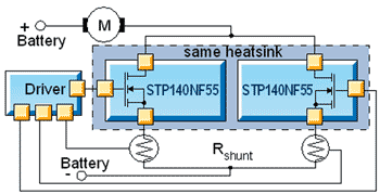
image from negative regulator linear application for power mosfets writeup on the following page

http://www.st.com/stonline/products/families/transistors/pow...

Hehehe .... Know 12AX7 has got to love this ......
okay Tim come get your spanking:P


[Edited on 19-10-2007 by Rosco Bodine]

5 volt @ 50A $12.79 free FedEx ground

Rosco Bodine - 21-10-2007 at 07:45

I ran across this ATX deal on pricewatch and thought I should share it :D

http://www.pcboost.com/store/viewitem.asp?idproduct=13811


This is the sort of deal which makes the idea
so appealing of adapting an ATX supply for use in electrolysis , as they are the cheapest efficient source of usable current level anyone is going to find .

DerAlte - 21-10-2007 at 08:40

There seems to be no excuse anymore for using that old battery charger!

With regard to electrolysis, I would be interested to hear what the electrolysis community here would consider the most important thing needed for a PS.

In some cases it seems that a strictly controlled voltage would be beneficial - to separate ions having differing SEP, e.g. In other cases, a controlled current might make more sense, allowing the cell to attain its natural potential; a case in point might be chlorate production, where the current density determines the product to some extent, and some of the energy is used to heat the electrolyte to encourage the side reaction of hypochlorite disproportionation, a purely chemical process. I know Rosco is trying to produce a flexible beast with both options .

@Rosco, had a look at your alternate NMOSFET choice. Much more Kosher, from the characteristics POV. I see you have come around to my view of SIMS! They have a place, but are only as good as the device models used. One has no idea what they are. They can be trusted for things like filters and passive circuits and even active opamp filters like the Sallen-Key type, provided you are far enough away from the unity gain frequency of the opamp.

@Rosco - I'll send a short U2U soon regarding something that occurred to me on reading this thread.

Regards,

Der Alte

Rosco Bodine - 21-10-2007 at 13:14

Quote:
Originally posted by DerAlte
There seems to be no excuse anymore for using that old battery charger!


YGTFR!:D Even without any fancy regulator , you could probably improvise a power resistor from a welding carbon , and a sliding clamp to roughly throttle the current from an ATX supply , or use a heating element as a power resistor and an alligator clip , like some have already done .

Quote:

@Rosco, had a look at your alternate NMOSFET choice. Much more Kosher, from the characteristics POV. I see you have come around to my view of SIMS! They have a place, but are only as good as the device models used. One has no idea what they are. They can be trusted for things like filters and passive circuits and even active opamp filters like the Sallen-Key type, provided you are far enough away from the unity gain frequency of the opamp.

Regards,

Der Alte


Yeah those folks at STMicroelectronics are talking my language on a couple of finer points regarding power mosfets . Especially with regards to ruggedness concerns , like putting a zener network bracketing the gate to provide ESD and inductive voltage spike protection , which would seem to be a no brainer for *all* mosfets to protect the fragile oxide layer from puncture . Yet so many manufacturers cut a corner there and just have one solitary zener which provides only a half-assed device protection in the actual cruel world power environment where transients
and static are there all the time . I never saw a mosfet
wearing its own antistatic wrist strap for the post assembly board residing time when its worries are a whole lot bigger than your body static and soldering iron during assembly :P
The folks at STM seem to understand that no brainer also :D
in having implemented their "SafeFET" architecture .


http://www.st.com/stonline/products/families/transistors/pow...

I am thinking that since the STM folks seem to have dedicated some development time and interest in linear power applications for mosfets , they may have worked out the models and modeling software for linear mosfet applications which will generate some intelligent simulations . Maybe I'll drop 'em an e-mail and see if they can be helpful .

[Edited on 21-10-2007 by Rosco Bodine]

12AX7 - 21-10-2007 at 17:40

Eww, why in God's green Earth would you want conduction from gate to drain!?

Tim

Rosco Bodine - 21-10-2007 at 18:15

There isn't any conduction there so long as the gate voltage is within the window values allowable by the zener voltages , which will be the case so long as gate drive voltage is normal polarity and allowable level .
The zener bracketing is invisible to any normal gate drive signal level voltage and normal polarity WRT drain or source .

But the zener from gate to drain will protect the gate oxide layer against the reverse breakdown potential possible to do the same sort of damage when voltage on the gate is higher than the drain as is provided in the more limited protection of a single zener from gate to source , which clamps normal polarity gate overvoltage .

The zener bracketing does a similar thing as what a varistor would accomplish in the way of clamping abnormal gate voltage without regard to polarity of the offending overvoltage . This will shunt any destructive gate voltage level of either forward or reverse polarity around the device .

On switching an inductive load this would be a very wise precaution .

Actually I have seen this same scheme used on the high impedance inputs of CMOS op amps which are unusually
vulnerable to being ruined by stray charges , and it is probably used to harden mil spec equipment against EMP as well .

It makes the mosfet bulletproof to stray or induced abnormal voltages . I see on the applications list they say this device is used in automotive anti-lock braking solenoid pulsing applications ...which makes sense .

[Edited on 21-10-2007 by Rosco Bodine]

12AX7 - 21-10-2007 at 20:30

Quote:
Actually I have seen this same scheme used on the high impedance inputs of CMOS


No, YOU HAVEN'T.

ICs are protected by clamp diodes which direct charge into the power supply rails. There is no gate-drain connection. Moreover, the rated power supply voltage on CMOS chips, by their very nature cannot cause gate breakdown, so a drain-gate zener would be useless.

If you connect a zener from drain to gate and supply breakdown voltage to that drain, the gate's voltage will zoom up towards the drain and BOOM, hole in the gate. You die, you lose, do not pass go, do not collect $200, but do please collect a large pile of exploded silicon, at your expense.

Every single switching MOSFET I have ever seen is rated for avalanche, so a zener protecting the drain is not only foolhardy and dangerous, but superfluous as well!

The argument ends here Rosco. Accept truth.

Tim

[Edited on 10-21-2007 by 12AX7]

Rosco Bodine - 22-10-2007 at 02:03

You aren't seeing the forest for the trees .

It is evident you aren't accounting for the fact that the usual gate to source zener would provide protection in the very scenario where you say the oxide would be holed by a drain voltage sufficent to cause avalanche .

What you are saying about avalanche operation of a mosfet is irrelevant to gate protection . You are describing a latchup scenario which doesn't involve gate destruction . Avalanche is recoverable if it is transient or limited ....it is gate destruction that is permanent .

For op-amps stray ESD and inductive voltages can be way above and beyond the rails with their own superimposed potentials that may even be quite opposite polarity to what the normal power supply arrangement is providing . The oxide layer between the metal gate and the mosfet body NPN structure is vulnerable to having that dielectric punctured , regardless of the polarity of the metal gate with respect to the body .


I have seen clamp diodes used different ways including to limiting the differential voltage between inputs , back to back zeners between the inputs and rails , and zeners combined with ordinary diodes too , and sometimes combinations of such diode arrangements across op amp inputs . But I'm not going to dig up every protection strategy example for protected CMOS inputs I can find just to prove it to you .

Well lookee here what I found

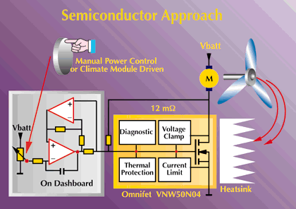
Rosco Bodine - 22-10-2007 at 11:18

Here's an STM scheme for infinite speed control of an automotive heater and air blower , which looks a whole lot like the negative regulator scheme which I have been proposing , not exactly , but very closely similar .


from the following page
http://www.st.com/stonline/press/magazine/prodnews/2ndedi00/...

The "On Dashboard Module" part of this regulator scheme doesn't seem to be fully disclosed in detail , and may be proprietary ....which goes precisely to what I was saying earlier about the devil being in the details :D

But the general idea of what I am trying to do is possible ,
as can be seen here .

[Edited on 22-10-2007 by Rosco Bodine]

12AX7 - 22-10-2007 at 16:01

Well as power supplies go,


Nuff said. You will not match the simplicity, parts count, performance and elegance of this design. Stop trying to think you can; you have shown time and time again that you cannot.

Twospoons - 22-10-2007 at 17:32

Quote:
Originally posted by Xenoid

Ahhh.. Twospoons, that was you was it! I had my eye on a constant current 60Amp HP supply on "Trade Me" but ummed and aaahed a little too long! ..


You snooze, you lose on Trademe. Buggered if I was going to let that one slip past!

@Rosco
Quote:

the spice simulator isn't sophisticated enough to give it a fair rendering


Or maybe you are not using it properly, or don't understand the results. You would be better with a transient analysis
- that will show up instabilites, and you can try things like line and load step responses


Quote:

The spice models for linear region operation of mosfets are pure crap too so that may be part of the simulation problem


Now thats just silly. SPICE only exists because modelling of fets, mosfets, bjts etc was needed by the semiconducter industry in order to design chips with thousands of devices. The device modelling is based on semiconductor physics, not a few textbook equations for gain. A complete BJT model has over 30 parameters IIRC.
If I get a screwy result from a simulator, my first assumption is that it is ME that's got something wrong. Garbage in - garbage out.

BTW that STM example of the fan controller looks like a PWM control at first glance (I haven't botherd to analyse it).

Rosco Bodine - 22-10-2007 at 21:27

Elegance ??? Hmmmm ......

Let's look at just a few of the things that are wrong with this design for now . Plenty of time later for all the other things :P

On the 12 volt range you have voltage control pot response from a minimum of 0 volts to a maximum of 6.2 volts.

On the 5 volt range you have a voltage control pot response from a minimum of 0 volts to a maximum of 6.2 volts.

On the 3.3 volt range you have a voltage control pot response from a minimum of 0 volts to a maximum of 6.2 volts .

I suppose the theory there was one size fits all or one size fits none at all , with the latter of those two possibilities being the design outcome . I fail to see
anything satisfactory about that scaling .

Maybe you could get around needing a switchable reference and get linear proportional full range response on your control pot ....but not like that .

Your op-amp supply ground in the Constant Current Modules needs to go to true ground or else you need to move your meter shunt to the other side of the array
so you don't create power rail noise rejection issues for your modules . Actually something better is to
use a local regulated supply at 10 volts gotten from the 12 volts , which provides a cleaner supply and noise immunity for the op amps and mosfet drivers .

What about having some status indicators for current and voltage mode ? Can't really watch for the voltmeter dip
since there isn't one .

As for performance , well that's an open question for your
one op amp per module solution , using that low of a low resistance current sensing shunt with one op amp .
There are stability concerns about the voltage controlled current sink configuration since the capacitive load of the Mosfet gate is a sort of worst case scenario load for an op amp . What is stable there with a 0.1 ohm shunt isn't necessarily stable with a 0.01 ohm shunt and which mosfet is being driven has a bearing there also .

IMO it is better in a VCCS module having a low loss , low resistance shunt to use a dedicated gain amp for monitoring the shunt voltage , another dedicated error amp , a unity gain buffer low pass filter driving an NPN source follower as a dedicated driver stage for the Mosfet . This arrangement seems to be what is required for the circuit to "hunt quietly" in a self dampening and rapid settling , stable servo lock fashion .

Be very clear on something , I am definitely not trying to match your work there nor have I been trying to think I can , nor do I even want to try ....why would I , or why would you even think that ? Is this supposed to be a farting contest or a legitimate technical discussion ?

Rosco Bodine - 22-10-2007 at 22:12

Quote:
Originally posted by Twospoons
@Rosco

Quote:
the spice simulator isn't sophisticated enough to give it a fair rendering


Or maybe you are not using it properly, or don't understand the results. You would be better with a transient analysis
- that will show up instabilites, and you can try things like line and load step responses


Been there , done that .......understand what I see .
You will sit for many long days setting and testing and noting results of different transient analysis scenarios , and still not catch the instability that an AC large signal , medium signal , signal sweep will turn up . Indeed you can NOT trust a Bode plot on small signal AC analysis when the voltages and results are contradictory , with phase being respected . I have spent many happy hours in front of real waveform analyzers and signal generators , and I know when a computer simulation is feeding me unbelievable bullshit as results . You can look at the voltage levels on the gate of a mosfet in a simulation and see when it is way below threshold , there should be no output . Just like you can look at signal levels on the inputs of an amplifier and tell
that something is wrong when the output is exactly the opposite of what it should be .

Quote:

Quote:

The spice models for linear region operation of mosfets are pure crap too so that may be part of the simulation problem


Now thats just silly. SPICE only exists because modelling of fets, mosfets, bjts etc was needed by the semiconducter industry in order to design chips with thousands of devices. The device modelling is based on semiconductor physics, not a few textbook equations for gain. A complete BJT model has over 30 parameters IIRC.
If I get a screwy result from a simulator, my first assumption is that it is ME that's got something wrong. Garbage in - garbage out.


I'll guarantee you the modeling was done for "normalized"
mosfet parameters pertinent to switchmode applications ....not linear region applications .

Here's one real life factor in linear region operation of mosfets ....*variable* transconductance , and its a hell of a lot lower than the fixed figure even perhaps 20% or less of what is stated as "minimum transconductance" , but the sims don't render linear region gate voltages accurately , not even spice 3 models cover it . What the sim generates looks nothing like the data sheets , but a great oversimplification with greatly flattened response , more than a volt to 2 volts away from what the manufacturers own data sheet says about threshold voltage and linear region in comparison with the same manufacturers spice model . The models are probably authored by some third party corner cutter or they would overlap perfectly with the data sheets :P

Quote:

BTW that STM example of the fan controller looks like a PWM control at first glance (I haven't botherd to analyse it).


Nope it's pure linear .

12AX7 - 22-10-2007 at 22:34

LOL, you didn't happen to realize that the gate threshold voltage varies by perhaps 4 to 6 volts in typical units, did you? Sounds to me like that model is just fine!

Re: my circuit;
I don't recall if more than 6V was even of interest. If so, then the 20k resistor can simply be removed. The control will then be linear from 0 to 12.4V (give or take actual zener voltage), so your voltage setting remains the same if you switch the jumper.

Indicators are external and any responsible scientist would have a proper precision voltmeter and ammeter on his experiment, regardless of the power supply in use. A light could be added to indicate constant current mode, with a comparator, trimpot, LED and resistor. This too is almost external. Performance will be excellent inside the bandwidth of this circuit, which should be at least 20kHz. (Any residual switching noise from the supply can be filtered with differential and common mode chokes and some capacitors.) None of your other points have any validity so I need not address them.

Tim

Rosco Bodine - 22-10-2007 at 23:47

Quote:
Originally posted by 12AX7
LOL, you didn't happen to realize that the gate threshold voltage varies by perhaps 4 to 6 volts in typical units, did you? Sounds to me like that model is just fine!


You don't really know too much about mosfets do ya?
1 volt variation maybe , 4 to 6 , you must be kidding .
And what about the transconductance value , it is definitely generally expressed as a saturation value plateau derived figure not even resembling the true much lower and slowly increasing figure for linear region operation .

Quote:

Re: my circuit;
I don't recall if more than 6V was even of interest. If so, then the 20k resistor can simply be removed. The control will then be linear from 0 to 12.4V (give or take actual zener voltage), so your voltage setting remains the same if you switch the jumper.

Indicators are external and any responsible scientist would have a proper precision voltmeter and ammeter on his experiment, regardless of the power supply in use. A light could be added to indicate constant current mode, with a comparator, trimpot, LED and resistor. This too is almost external. Performance will be excellent inside the bandwidth of this circuit, which should be at least 20kHz. (Any residual switching noise from the supply can be filtered with differential and common mode chokes and some capacitors.) None of your other points have any validity so I need not address them.

Tim


Excuses , excuses :P

I suppose it would be pointless also to note that bandwidth is a somewhat ambiguous concept with regards to this regulation scheme , so no bandwidth figure having any general meaning can actually be cited . You see the full power bandwidth is a function of where the current limit is set in relation to how much baseline current is flowing , and as the power is increased towards the level where current limit is approached , the bandwidth decreases to zero or unity as for DC .......however you wish to characterize that zero hertz bandwidth . So you have to characterize bandwidth as a function of percentage amplitude modulation (regulation) above and below any given voltage level , like plus or minus 1% @90% full current output for example .

Hey , I know ...you can just say it regulates good , or it regulates poorly ....and for bandwidth , well whatever :D

You will be lucky to get a stable sweep from zero to full current at rated voltage to even 1 kHz driving the power mosfet directly with an op-amp . But you might get it up to 2 or 3 kHz using the strategy I suggested ....but thats probably an outside figure , and half of that is more likely for either scenario . You won't see much bandwidth in linear operation for these power mosfets which have a lot of capacitance , because of the peaking / overshoot which appears as you try to drive them faster . They are sluggish unless hit with a hard and fast rising drive signal and then they overshoot the mark so you end up having to tradeoff speed for accuracy and stability for linear operation . Otherwise the mosfet will go into the porpoising routine of oscillation unless you slow it down . A ripple generator is easily achieved here , as in big ripples .

Thinking yours won't oscillate may be just so much wishful thinking .

12AX7 - 23-10-2007 at 09:13

Oops, worded misleadingly: should read "varies from perhaps 4 to 6 volts". Example: STW11NB80 Vgs(th) (Id = 250uA, Vds = Vgs) ranges from 3 to 5V, for a range of 2, or 4 +/- 1 V.

FETs are notorious for irregular Id and Gm parameters, both due to manufacture and variation with temperature.

Your further objections are again invalid and needn't be addressed.

Tim

Rosco Bodine - 23-10-2007 at 10:09

Yeah a range of 2 to 4 for threshold is more like it .
And it's not just that the Gm varies from unit to unit ,
but it varies in the same unit depending on the level of saturation .

You say my other objections have no validity , maybe you would expound on that and say exactly where .

Since there seems to be little agreement so far ,
how about this ....would you agree that in this particular
and peculiar sort of circuit configuration , that really no spice AC small signal simulation is trustworthy as any substitute for actual breadboarding and a real instrument analysis of the actual physical circuit ?

Otherwise we could talk about theory forever here and both be wrong . I have put some of these things through their paces in spice sims , and gotten good DC solutions , but garbage results for AC and transient response .

12AX7 - 23-10-2007 at 12:23

I don't even use SPICE.

Many people do use SPICE, and get excellent results from it. It's definetly the professional tool to explore things without a dusty old breadboard. Winfield Hill, author of Art Of Electronics, uses it, among other professionals I know. Others use it and get excellent results, only to discover that their circuits never work in reality. Still others never get any simulated results from a circuit which works just fine in reality. Legendary IC designer Bob Widlar has shaken a breadboard in one hand, yelling "according to SPICE, this circuit doesn't work!". You can talk to them yourself if you need hints and tips on SPICE.

I can analyze this circuit quite fine from here, anyway.

At worst, three phase shifts -- two op-amps and the 220 ohm gate resistor and the gate capacitance -- conspire to create a phase-shift oscillator, probably in the 50 to 200kHz range. Just where depends on the op-amps used. If the voltage error amp is fast, I can guarantee you this circuit will oscillate. That's your fault for irresponsibly using an op-amp too fast, or too undercompensated for the loop it's in.

A typical compensation scheme would be a output-to-(-)in capacitor at the op-amp, adding a series resistor to that input if its impedance isn't high enough (as in the CCM) or constant enough (as at the reference pot) to assure compensation. Another approach is to add loop NFB to the op-amp locally, via resistor, to limit the amount of NFB delivered by the external loop.

The error amp should be about 5 times slower than the CCM, so the CCM should use a reasonably fast op-amp with good drive capability and slew rate. Probably, a regular TL074 could be used, with an emitter follower to provide suitable gate drive. A more powerful op-amp with the same general specs would be more suitable, I just don't know any offhand. Full signal bandwidth can be expected from DC to 100kHz or so.

If the MOSFETs chosen are IRFZ44N, the "miller charge" is 23nC, or over 2 microseconds, a constant current of less than 15mA (since I == dQ/dt). At 10V, a typical gate resistor would then be about 10/0.01 = 1kohm or less, so I wrote 220 ohms, which will supply ample gate current to the MOSFET in less time than the op-amp will notice. Some compensation may still be needed, which as I've indicated is a simple adjustment.

With the CCMs in the 100kHz range, the error amp should have compensation down to the 10-20kHz range. A jellybean LM358 could be used, which is slow enough as-is that it will probably be stable with no changes.

Tim

Rosco Bodine - 23-10-2007 at 15:12

Quote:
Originally posted by 12AX7
I don't even use SPICE.

Many people do use SPICE, and get excellent results from it. It's definetly the professional tool to explore things without a dusty old breadboard. Winfield Hill, author of Art Of Electronics, uses it, among other professionals I know. Others use it and get excellent results, only to discover that their circuits never work in reality. Still others never get any simulated results from a circuit which works just fine in reality. Legendary IC designer Bob Widlar has shaken a breadboard in one hand, yelling "according to SPICE, this circuit doesn't work!". You can talk to them yourself if you need hints and tips on SPICE.


From what I have seen of it so far , spice is good for initial layout and component selection and confirming DC solutions for various selected conditions , like a snapshot of control loop instantaneous values ...but it is inept at simulations which are dynamic across time and frequency sweep changes ......unless it involves a particular templated circuit arrangement for which it has been specifically debugged and tested in advance . It gets lost easily and doesn't have any automatic self-check on the integrity of the lies it starts telling .

Quote:

I can analyze this circuit quite fine from here, anyway.

At worst, three phase shifts -- two op-amps and the 220 ohm gate resistor and the gate capacitance -- conspire to create a phase-shift oscillator, probably in the 50 to 200kHz range. Just where depends on the op-amps used. If the voltage error amp is fast, I can guarantee you this circuit will oscillate. That's your fault for irresponsibly using an op-amp too fast, or too undercompensated for the loop it's in.


Below a few kHz the phase shift is negligible for lightly loaded op-amps where the load is purely resistive , but you are right about the gate capacitance being a problem , and it is only one of several problems which aggravate the situation there with the mosfet . There is other capacitance about that mosfet and the way it responds is current dependent , so what compensation is worked out for one operating point isn't effective at a different operating point .

You have it exactly backwards with regards to the speed requirement for the voltage error amplifier as compared to the power element . The error amp needs to be fast so it can sample and correct on the fly several times while the power element is still in transition . Then a buffer stage having a low pass characteristic averages and derives a correction signal at speeds which can be followed by the power element . That buffer response then establishes your maximum bandwidth .
Quote:

A typical compensation scheme would be a output-to-(-)in capacitor at the op-amp, adding a series resistor to that input if its impedance isn't high enough (as in the CCM) or constant enough (as at the reference pot) to assure compensation.

Yeah that was a first approach tried for compensation ....but the problem there is you already have about the limit of a capacitive load on the op amp with the mosfet , and now you are going to add *more* capacitance for filtering ...which has
an effect that is quite different from what you may have wanted ......especially for different operating points .
That is precisely what leads to having to use as a buffer an active filter driving an NPN source follower for the gate drive of the mosfet . It is really very frustrating to see what works so perfectly for one load and voltage , go completely to hell for a different load and voltage because of the mosfet behavior changing beyond the capability of compensation
intended to tame it .

Quote:

Another approach is to add loop NFB to the op-amp locally, via resistor, to limit the amount of NFB delivered by the external loop.

It's more than just another approach , you probably have to do both that and the earlier compensation strategy as well .
That is partly why I added a gain stage , early on . But more to the point of what you are saying is perhaps setting a fixed
gain , high but fixed , perhaps 10,000 ? ....for the current error amplifier in the VCCS module ? Maybe .....I think I already looked at that as a limiter possibility , and left it undecided , unresolved . That could do some good .
Quote:

The error amp should be about 5 times slower than the CCM, so the CCM should use a reasonably fast op-amp with good drive capability and slew rate. Probably, a regular TL074 could be used, with an emitter follower to provide suitable gate drive. A more powerful op-amp with the same general specs would be more suitable, I just don't know any offhand. Full signal bandwidth can be expected from DC to 100kHz or so.


You need to give that some more thought :P The usual semantics for bandwidth simply do not apply to this circuit . Maybe if there was a 4 or 5 msec overcurrent delay before current limiting was invoked .......but not so long as it has hardwired instant current limiting .
Quote:

If the MOSFETs chosen are IRFZ44N, the "miller charge" is 23nC, or over 2 microseconds, a constant current of less than 15mA (since I == dQ/dt). At 10V, a typical gate resistor would then be about 10/0.01 = 1kohm or less, so I wrote 220 ohms, which will supply ample gate current to the MOSFET in less time than the op-amp will notice. Some compensation may still be needed, which as I've indicated is a simple adjustment.


Simple for one operating point yeah , but effective across the entire range of output capability .....not so simple .
Quote:

With the CCMs in the 100kHz range, the error amp should have compensation down to the 10-20kHz range. A jellybean LM358 could be used, which is slow enough as-is that it will probably be stable with no changes.

Tim


Yeah an inherently slow op amp could actually have appeal for the VCCS current error amplifier in regards to stability concerns . The slower it slews the less overshoot will
be caused on the mosfet . You don't cure the overshoot
by driving the gate harder and faster , but by driving it gentler and slower .....which gives you stability , but of course kills the bandwidth . See the dilemma ?

Stop thinking microseconds if you want to see a stable control loop .....think milliseconds , and many of those for settling times .

With a 1 ohm sense resistor you might get 100 kHz range ,
but not with a 10 milliohm .....nada no way no how not today :D

12AX7 - 23-10-2007 at 17:28

Rosco,

Most of your points are backwards. The loop around the error amp, for instance, must be faster, or else phase shift will approach 180 degrees at some frequency and there it will oscillate. Two op-amps of the same speed both phase shift by almost exactly 90 degrees for any frequency over, say, 20Hz (yes, 20Hz, I'm not kidding, read the datasheets some time), making a loop containing only two completely unstable without compensation. With the cutoffs staggered and gain and feedback limited, the phase shifts do not coincide and it can be stabilized without half-assed patching.

The "hand waving" way to demonstrate this is to note that a faster error amp will see the error, then seeing it growing, and see it not responding, and the feedback signal is therefore much larger than it should be (excessive derivative in the PID term). The slow amp eventually responds by passing this amount to the output, which overcompensates for the original error, causing overshoot and so forth. If you're lucky, it will ring down. If you aren't, it will ring up and oscillate.

Learn control loops some day. I have been playing with electronic loops for years. I have more experience than you.

Tim

Rosco Bodine - 23-10-2007 at 19:29

Quote:
Originally posted by 12AX7
Rosco,

Most of your points are backwards.

Ya think ?
Quote:

The loop around the error amp, for instance, must be faster, or else phase shift will approach 180 degrees at some frequency and there it will oscillate. Two op-amps of the same speed both phase shift by almost exactly 90 degrees for any frequency over, say, 20Hz (yes, 20Hz, I'm not kidding, read the datasheets some time), making a loop containing only two completely unstable without compensation.


Phase shift is not just some magic number like 90 degrees
"per op amp" , but it is related to gain , frequency , and the sort of load .

If you have sufficient phase shift in a number of series stages , then the phase shifted signal arrives on the feedback return path in matched phase with the input signal on the other op amp input . Common mode rejection
then excludes response to the like phase signal and amplifies the difference . So all the op amp effectively sees is two differing DC level inputs . And the stability of the loop holds ..... out to as high a frequency as the phase remains matched reasonably in sync .
Quote:

With the cutoffs staggered and gain and feedback limited, the phase shifts do not coincide and it can be stabilized without half-assed patching.

Making the phase shifts coincide at the error amp inputs is precisely what you want to do , it's having them go 135-180 degrees out that causes any problem . It's keeping them in sync across a 120:1 range of operating current that is the challenge and no small one .
Quote:

The "hand waving" way to demonstrate this is to note that a faster error amp will see the error, then seeing it growing, and see it not responding, and the feedback signal is therefore much larger than it should be (excessive derivative in the PID term). The slow amp eventually responds by passing this amount to the output, which overcompensates for the original error, causing overshoot and so forth. If you're lucky, it will ring down. If you aren't, it will ring up and oscillate.

Without a buffer , that's right . Think about the way a cruise control works . The driveshaft sensor and error amplifier are very fast . The vacuum solenoid throttle linkage buffer stage is much slower , and then the throttle acellerated vehicle itself is slower responding still . Works like a charm .
The response time hierarchy there is correct for stability .
A vactrol could serve a similar purpose as a sort of DC restorer buffer stage in this control loop , since it would isolate the stages and render phase moot due to the slow response and storage time of the CdS element in the vactrol optoisolator . For a millisecond or so it acts as a sort of "sample and hold" continuously refreshing signal reference .
Quote:

Learn control loops some day. I have been playing with electronic loops for years. I have more experience than you.

Tim


Hell , I'm trying to learn everything I can , but it's hard to teach an old dog new tricks :P

I have about four sample packages of PerkinElmer Vactrols
sitting in front of me , and they are probably older than you are . The ones I have used before came in very handy for
situations just like this where it became necessary to remedy phase and voltage incompatability issues in a control loop with a proven performer from way back .

I think they were originally developed as noise free potentiometers for use as volume control faders in tube audio theater sound systems . No static , no snap crackle pop . Smooooth :D

They probably even have an honest injun spice model for them ......unlike the situation for power mosfets :D

[Edited on 23-10-2007 by Rosco Bodine]

DerAlte - 23-10-2007 at 20:57

If any of you are seriously considering making a constant current or a constant voltage regulated supply, ignore all the ranting above and search for manufacturer's application notes on the web. Here's a starter (a modicum of electronic knowledge is needed):

http://www.national.com/appinfo/power/files/f4.pdf

I suggest the above posts between the two antagonists be put into Whimsy - pure whimsy. If you are going to design a feedback circuit please learn the fundamentals as explained in any Elecronics 100 course for engineers, who have to make things actually work. Stop wasting our time.

Regards,

Der Alte

12AX7 - 23-10-2007 at 21:16

Quote:
Originally posted by Rosco Bodine
Without a buffer , that's right . Think about the way a cruise control works . The driveshaft sensor and error amplifier are very fast .


I suspect you should go work for Chrysler, then.

Mom's minivan, a 2000-something Voyager or whatever it is, has a cruise control with a response time of about 1 second. It really is quite slow, and I can bet that the engineers at Chrysler played with it and decided that there was enough windage in the slowly-responding engine (computer controlled, bah!), automatic transmission and vehicle weight that it would've oscillated horribly without a severely low pole to let it work out. Now there's something you don't want to see, velocity oscillation on the highway. That would be weird, annoying and in traffic, dangerous. Or even worse, the gas pedal twitches up and down, gotta be bad for the engine.

On the other hand, Dad's Nissan Pathfinder, with manual transmission, has very little windage in the drivetrain, so its cruise control is much faster -- still slower than the vehicle, but because there are fewer phase shifts in the loop, it is able to respond and regulate much better in turn.

Tim

DerAlte - 23-10-2007 at 21:35

@Twospoons - re your post 22-10-2007:

Quote:
Now thats just silly. SPICE only exists because modelling of fets, mosfets, bjts etc was needed by the semiconducter industry in order to design chips with thousands of devices. The device modelling is based on semiconductor physics, not a few textbook equations for gain. A complete BJT model has over 30 parameters IIRC.
If I get a screwy result from a simulator, my first assumption is that it is ME that's got something wrong. Garbage in - garbage out.


I must say up front I am not a great fan of SIMS, but they do have uses, especially for the tedious business of tolerancing, etc - once you are sure the nominal circuit is making sense. GIGO - sure! But sometimes the garbage is created internally by a progam fauly causing out of range values, divide by zero etc.

As to junction transistors using 30 parameters, I doubt it. As for physics, well, most SIMS merely use the equivalent circuit parameters as engineers do by hand - from the data sheet. I'd find it hard to define 30 parameters. And for some uses that may be inadequate. Avalanche conditions, e.g.

Most of the junction transistor theory was around in the 1950s, even before my time! The Early effect was reported in 1952; Ebers and Moll considered large signal behavior in around 1953, IIRC.


Even transistor design itself has been reduced to fairly elementary considerations. It is not handled by the type of program we are talking about here.

What I used to object to is the attempted use of the simulations to actually design circuits rather than merely analyze them. Too many scientists and engineers today use a computer program and not their own brains. A computer program, at best, represents some one else's brainwork and reduces the person using it to a mere operator of a machine, without any talent of his(her) own. And that where GIGO comes in, in force...

Regards, Der Alte

Twospoons - 24-10-2007 at 19:13

In defense of SPICE :

SPICE Model parameters - BERKELEY

I appologise - I was wrong. There are in fact 41 parameters that can be applied in the latest versions of SPICE BJT models.

The model now used is the Gummel-Poon model, an extension of the Ebers-Moll model to cope with high bias levels.
Have a look at the link.

I agree that you can't use SPICE alone to design, but you can use it to verify. Using spice allowed me to succesfully design a laser pulse reciever, that picked up 1pJ, 16MHz pulses, and only needed 150uA Iq. I would never have got the bastard temperature stable without the simulations (at least, not in 3 days!).
I like it, use it, and find it a handy tool in my engineering arsenal.

Not all simulators are built equal either. There exists a set of standard test circuits for evaluating simulator performance. I use Simetrix - which could achieve convergence on a ckt with 17,000 mosfets in it, IIRC.

DerAlte - 24-10-2007 at 21:58

@Twospoons

Read your reference and stand corrected! But, if you are going to use, say, a generic 2n222 how many of those 41 parameters really apply, and how many are guess work or default values? I am sure manufacturers don't supply models with all 41! I am even more sure that less than 1% of engineers use them either, apart from device designers.

True it's a hell of a long time since I designed anything truly analog (25 years) having become a theoretical type working digital concepts for things like DSP processors, so I have no idea of the versatility of the modern SPICE program. I grew up with h, y, and z parameters and used them if I could get them, otherwise the usual equivalent cct parameters. Matrix algebra was hell using Fortran (I shouldn't even mention I used Algol also!).

But no program beats a good brain, except for speed.

Regards,
Der Alte

12AX7 - 25-10-2007 at 08:16

Lots of Onsemi datasheets provide copious graphs of parameters, even all the rarely seen h-parameters besides hfe.

Some, like the 2N2222 and MJE350, among hundreds of others, are never specified for some parameters. Things like fT, hFE vs. Ic, etc. simply may not be in their specification. The 2N2222 is from a wider-tolerance silicon era, after all.

Tim

Twospoons - 25-10-2007 at 12:48

I find the fancy models tend to be more available for the fancy transistors - low noise RF transistors, for example. Some manufacturers supply more detailed models than others. Its easy to see which - the model file is just a text file.
12AX7 is quite correct about the garden variety semis - the process spread is so huge, and so many different fabs are making these generic parts, that the models are quite simple.

Appologies for hijacking this thread into a discussion on SPICE. I'll say no more.

@12AX7 Looking at your CCM module, you have the neg supply to the opamp connected to Vout. Since this is operating off a PC supply, would it not make more sense to use the -12V rail for the neg supply of the amps, since it is there for free? All my experience suggests the opamp will work better with stable split rails.

[Edited on 26-10-2007 by Twospoons]

Xenoid - 25-10-2007 at 14:14

@Rosco Bodine
@12AX7
@DerAlte
@Twospoons

Hi guys, sorry to interrupt your arguments, but I have a question about modifying AT/ATX supplies.

I have several supplies which I have modified in the usual way of removing all the surplus wiring and fitting terminals for the +5V supply and a switch if required. I use these for chlorate cells etc. and adjust the current with adjustable carbon rod resistors as mentioned elsewhere.

I would like to be able to vary the +5V supply from say about 2-3 Volts up to about 6-7 Volts this would allow me to do away with the resistors for (per)chlorate cells. I am NOT interested in converting the supplies to full laboratory supplies or even constant current at the present time.

I have attached the circuit for a Seventeam AT supply, which I obtained here;

http://www.users.on.net/~endsodds/smps.htm

Is it possible to place a potentiometer in the +5V feedback input for the TL494 (pin 1)(shown in red). This appeared to be alluded to in the garbled reference mentioned earlier by Dann2;

http://www.fieldlines.com/story/2007/10/18/16953/116

This would necessitate changing the overvoltage sense input of the LM339 (pin 7)(shown in green) presumably by tying it to the +5V regulated line so it no longer has any effect.

At the same time as varying the +5V output the other output voltages will vary also, but this doesn't matter as I am not interested in them. The 12 Volt auxiliary supply, (marked in purple) will also vary significantly. If this variation is too great, this supply could be replaced with a small transformer and a 7812 regulator etc. which could be mounted upside down inside the power supply lid.

I gather some supplies already have a trimpot for adjusting the +5V output exactly (the Seventeam doesn't) wouldn't it just be an expansion of this feature?

Would this work, or is it a bit more complex than this. Can you suggest any other simple way of varying the +5V output up and down by a few volts.

Regards, Xenoid

230cct.gif - 27kB

Rosco Bodine - 25-10-2007 at 15:40

I'm thinking replace R38 with a 2.2K fixed and 5K pot added in series to pin 2 of the TL494 may be all you need to do .

Connect the wiper to one end of the pot resistance attached
to either the pin , or the end of the 2.2K fixed , so that as
the pot is adjusted , your substituted adjustable value for the old R38 varies from 2.2K to 7.2K .

Set the pot so the total value of the string is the same 4.7K as before , and watch a voltmeter reading on the output as you try to vary it a little bit up or down .

The meter will tell you if I am guessing right or not .

[Edited on 25-10-2007 by Rosco Bodine]

Xenoid - 25-10-2007 at 16:24

Well Rosco, that's essentially what I was going to do until I read the thread on the page that Dann2 posted, (see my previous post). These guys do the voltage adjustment on pin 1 of the TL494. They also have a circuit for current limiting.
See here;

http://www.anotherpower.com/gallery/dinges/PC_PSU_schematic?...

Unfortunately it's a bit of a rats nest pencil sketch!

Regards, Xenoid

[Edited on 25-10-2007 by Xenoid]

Rosco Bodine - 25-10-2007 at 16:42

You could try the same setup described above as a substitute for the R41 3.9K .

One or the other should work ...or it may required
a ganged pair to do both simultaneously .

I looked at that pin 1 and wondered about it , but figured
pin 2 more likely .

I'll see if I can find a data sheet for the TL494 and
maybe I'll know more then if I can see what's in it ,
and where the internal reference is .

Twospoons - 25-10-2007 at 16:52

It's really hard to see but it looks like there is fb from +5 AND +12 ? Which to me suggests changing R47(?) to be variable. I can't read the values.
Or use Rosco's method, but don't tweak it too far, or you might have to muck about with the compensation network on pin3.

You should be OK with the Aux rail. data sheet says the '494 can handle quite a bit of vcc ( up to 40V).

TL494 datasheet

[Edited on 26-10-2007 by Twospoons]

Xenoid - 25-10-2007 at 16:59

@ Twospoons

The original circuit is here;

http://www.users.on.net/~endsodds/230cct.jpg

It's a little easier to see.

Regards, Xenoid

Rosco Bodine - 25-10-2007 at 17:17

@Xenoid

The datasheet says something entirely different from that note #2 on the schematic you posted about functions for
pins 2 and 3 ....
it isn't pins 2 and 3 that are the error amp inputs but pins 1 and 2 instead ......pin 3 is for frequency compensation .

Soooo you should be able to change the biasing as I suggested at either pin 2 or pin 1 with the same effect .
As the better choice I think go with what I said first above .

BTW the internal reference is 5 v which is actually an
internal regulator providing +5V out at pin 14 , for local biasing needs ect. That is what I was guessing when
I made the first suggestion , as I didn't believe then
what the schematic said about pin 3 , and have confirmed that now .

The stated values shown on the schematic don't look
correct for the biasing at pin 1 , so I am trusting the data sheet and intuition here ...for already having caught that schematic in one blunder and expecting more :P

For example R40 should equal R41 corresponding with
R38 equaling R42 .......in order to set the operating point
properly for 5 volts . But the schematic shows R40 as 10K
instead of the 3.9K it should be :D Also the same for R39
which is wrong at 24K and should be 18.7K .......there's two good reasons I don't trust that schematic additional to the
discrepancy in note#2 about the pinout .

Wait a second ..... I see now what they are doing there , combining 12 and 5 to get a parallel sum at the 3.9K .....
a 2.5 volt derivative from the combined 12 and 5 signals .
It's okay there , they are just shortcutting having independent monitoring and regulation for the separate
12 and 5 ....must be an older design supply .

You might want to disconnect the 24K R39 and replace the
R40 10K with a 3.9K if you are going for variable voltage of the 5 volt output only .......that will give you a dedicated more accurate regulation on the varied 5v output you are using , while letting the 12 volt output go where it will .

[Edited on 25-10-2007 by Rosco Bodine]

Xenoid - 25-10-2007 at 17:46

@Rosco

Yeah, I remember seeing that Note #2, I should have mentioned it!
I also don't understand those bias resistors around pin 1.
Have you managed to have a look at the pencil sketch circuit, I mentioned above, note they are adjusting the 12V supply not the 5v.
I have the power supply the circuit refers to, I'll check the circuit.

Edit: The resistor values around pin 1 are correct according to my circuit board. My supply uses a Sharp IR3M02 which is pin compatible with the TL494.

Regards, Xenoid

[Edited on 25-10-2007 by Xenoid]

[Edited on 25-10-2007 by Xenoid]

Rosco Bodine - 25-10-2007 at 18:07

I figured out what is up with pin 1 and edited my message above .

I think you need to separate your feedback for 5 and 12
and just use one or the other ...for accurate regulation
of the one you are using and varying . That could be a problem depending on how stable or wild the one freed up will be . Lightly loaded , I'm thinking the freed one
should be okay ....but can't be certain .

Where does that "power good" output go ...to an LED ?
If it loops back into some sort of power on self test , it
could be trouble and might have to go .

[Edited on 25-10-2007 by Rosco Bodine]

Xenoid - 25-10-2007 at 18:28

@Rosco

Sorry to keep bugging you!

Why is it necessary to have feedback from both the 5 AND 12 volt outputs. Since they come off the same transformer. If the TL494 ramps up to correct the 5V supply, wont the 12V supply be increased accordingly and vice versa! Thats why I was worried about the 12V auxilliary supply going too low or high when the 5V is changed from say 3-7 volts.

Am I missing something here, I might be getting out of my electronics depth with SMPSs.

Edit:....."Where does that "power good" output go ...to an LED ?
If it loops back into some sort of power on self test , it
could be trouble and might have to go."
It went to the MB as far as I know, it's disconnected, the supply works fine!

Regards, Xenoid

[Edited on 25-10-2007 by Xenoid]

Rosco Bodine - 25-10-2007 at 18:40

It's just a corner cutting way of regulating two outputs at once ......not really true regulation of 5 and 12 independently , but a "presumptive" sort of limiting regulation of two outputs at once .....figuring that more or less one follows the other since they are running from the same oscillator .

Really what I get from this now is you should use the 2.2K
fixed resistor in series with a 5K pot like I said earlier ,
but use the series of those two as a substitute for R40 and just remove R39 . Set your initial series resistance
for 3.9K sum 2.2K + 1.7K "in the pot" . That will be your
nominal 5 volt out and you can adjust it up or down from there .

Allowing the 12 volt output to float , put a light load on it
to help it not "float away" :P

And you will have to disconnect the overvoltage sensing
to pin 7 on the LM339 . Just tie pin 7 to ground .

Leave the lead that went to it open and just cap it off .

I think you will be in business then .

But maybe keep a fire extinguisher handy , just in case:P

BTW here are some output ranges for different value
fixed resistors in series with the 5K pot .

Using a 2.2K .... 3.9v to 7.1v
Using a 1.8K .... 3.65v to 6.86v
Using a 1.5K .... 3.46v to 6.7v
Using a 1K ........3.14v to 6.35v
Using a 680 ......2.94v to 6.14v


[Edited on 25-10-2007 by Rosco Bodine]

12AX7 - 25-10-2007 at 20:29

On that schematic, to make it adjustable;

Check the rating of C16 and C17. They must be 10V rated for the range you suggest.

Nix the +12V winding. No need to cut it all off, but do remove the filter capacitors and ZD1. Optionally, you can also remove the rectifier, which will still cause a small amount of loss, even though unloaded. (Move D11 accordingly, of course.) You still need the fan, so move it to the -12V supply. You could keep the +12V supply for this reason, but it's much more beefy than you need.

For control, nix R39 and change R40/R41 to a 10k potentiometer. Add a resistor in series with its GND leg so you can't adjust voltage to +infinity (which would be useless, as PWM would max out to no benefit -- you lose active regulation and get some unspecified output voltage). Don't muck with the 2.5V reference (R38, R42). R43 and C26 need a constant impedance to function properly.

On overvoltage, you can cut it altogether (nix R22, R19 and D14) and ground it (for example, now that the top end of R23 is loose, it could be grounded). Don't muck with the voltage divider (R32, R33), because you do want current limit.

As you adjust the input and output voltage and vary the load current, the PWM ratio changes to compensate. This circuit works by chomping a variable width "up" pulse, followed by dead time (Q1, Q2 off), followed by an identical "down" pulse and another dead time. These two pulses are flipped into forward-going and off periods by the rectifiers, and this doubled-up PWM is filtered by the choke. The percent on-time therefore corresponds to the average, which is filtered and given to you at the output. As line voltage changes, the voltage on the transformer changes, so the output would change as well. This must be compensated for with a proportional change in PWM. Resistance in the circuit (power line sag, the transistors, transformer, rectifier, choke) causes some voltage drop with increasing load current, requiring somewhat less PWM change to compensate. Since PWM is limited (up to 48% or so, depending on C27 -- see datasheet), there is only so much compensation to apply in this circuit. As such, you can only adjust the output voltage so high, given some load current and line voltage.

The practical lower limit is where PWM becomes so short that it's squegging (runt pulses, only enough to maintain voltage). This is probably at few volts. You cannot draw a constant power limit from this type of power supply: you are limited by the current capacity of the circuit. The SOA is roughly square.

Speaking of SOA, do keep in mind that this power supply was NOT designed to put all its VAs into one winding. You WILL need a beefier filter choke (MWC and L5), rectifier and power transformer secondary (ooh, adventerous this one) to pull that off.

Tim

Xenoid - 25-10-2007 at 21:08

Thanks guys;

I've just had a quick go at modifying;

I removed R39 (12v feedback) and simply replaced R40 with a 10K pot, as I didn't happen to have a 5K. I disconnected the overvoltage on the LM339 and grounded pin 7.

I connected a small load (10 ohm, 20W resistor) and powered up, I was able to control the voltage from about 2.5V up to about 9.5V which is about what I expected.

The fan stops running at about 3.8V as the auxillary supply drops, and really roars away when turned up to 9.5V. I guess the 12 volt auxillary is changing from about 6V to 22V. I didn't get around to measuring it. I think it will need a seperate supply!

Regards, Xenoid

Rosco Bodine - 25-10-2007 at 21:23

The current limiter is still operational and works from sensing on the primary . You can make the current limiter adjustable by substituting a 5K pot for R33 . The supply should still deliver its rated current on the 5v output .

I disagree with cutting off the 12 volt winding and moving the fan to the -12 . I would leave that as is .

I disagree with using a 10K pot like 12AX7 is saying , going to the node pin 1 and R41 .....just pick one of the combinations of fixed value R and a 5K pot as I have charted above , substitute that series combination in the place of R40 and remove both R40 and R39 .

I do agree removing ZD1 and additionally removing R19 , R22 , R23 . They become parasites on the new configuration .

You could probably use a power resistor and a 12V 5W zener
to protect your fan or use a cheapie fixed regulator in front of it .

That's strange with the voltage going to 9.5 with the 10K pot
as it should've stopped at 8.9v . Must be some wide tolerance resistors on that board .

[Edited on 26-10-2007 by Rosco Bodine]

Xenoid - 25-10-2007 at 22:28

I can't see any way around not having a separate supply for the fan.

It's no good if it stops operating when the voltage is turned down below 3.8 volts. My chlorate cells tend to run at about 3.0 - 3.5 Volts and 20 Amps. At 20A the fan will need to be going flat out.

I guess I could use a mains voltage fan, if I can find one!

By the way, this Seventeam circuit is pretty generic, and many of the early AT supplies which utilise the TL494 and the LM339 (or equivalents) have essentially the same circuit.

Regards, Xenoid

Rosco Bodine - 25-10-2007 at 23:03

If the -5 output has enough current capability
for running the fan......

Perhaps move the negative for the fan to the -5 output
and then use a power resistor and 12v 5W Zener
across the motor leads to limit it .

At 60% output , 3 volts on the usual 5 volt , you would see
-3 to +7.2 or 10.2v for the fan as minimum .....right ?

And then as you crank it up ....the power resistor would burn off anything over 12 .

Xenoid - 25-10-2007 at 23:25

Yes Rosco, that sounds reasonable. I'll try it tomorrow.

Actually the fan has an added on thermistor control board which is not shown on the circuit. I'll try removing it, and check exactly what the fan requirements are.

I'll also check the current limiting idea as well.

The recycling centre has a large bin of AT type supplies, they cost about $2 and they all seem to work OK. Even if they don't, there's more than $2 worth of parts inside - incredible value!

Regards, Xenoid

Rosco Bodine - 26-10-2007 at 14:01

Not meaning to too much overstate the obvious here

* If * there is a good schematic available for any common and even higher current SMPS of the more recent ATX specification ....
a similar conversion could possibly be done there as well,
by way of this kind of unauthorized reverse engineering .

warning ! no user servicable components inside !
warranty void if seal is broken ! :P ROFLMAO :D:D:D:D

If this power supply was sentient , and it sensed your
approach with diagonal cutters , soldering iron , test meter , magnifying work glasses and a little bag of parts ..... just imagine the poor things harness grommet
would be constricted so tightly it would shear the cables
in two :D

Now just hold still Mr. PS ...this won't hurt a bit :D
Just making a little adjustment here .

Any of you fellow nerds talk to the hardware on which you are working as if it can hear you ? Hehehe , the doctor will see you now :P

Xenoid - 26-10-2007 at 21:12

@ Rosco

Here's an ATX circuit:

http://www.pavouk.org/hw/en_atxps.html

I notice the "auxiliary" power is driven by a separate transistor oscillator, transformer and a 7805 "second power supply". I guess this part of the circuit could be used to drive the fan as it is independent of whatever output voltage changes one might want to make.

I have an ATX, it has 5V at 24A and 3.3V at 14A but I'm only using the 5V at the moment. To get it going all that was required was grounding the PS-ON wire, if I remember correctly. I put a small load across the output to insure it started OK when not connected to anything. It is rated at 230W but the combined output of +5V and +3.3V is only 130W. I guess by ATX, you're thinking of the more "modern" 300-400W supplies. I haven't seen any of these at the recyclers yet!

This might be a better proposition to make adjustable as I haven't drilled holes in the front panel for a switch (it has a switch on the rear) and an indicator light, so there is still room for a pot or two!

I notice the LM339 in this circuit is not used for the over voltage/current protection.

There are several web sites for modifying these supplies, they are usually modified to produce +13.5V for "ham" radio operators, like here.

http://www.webx.dk/oz2cpu/radios/psu-pc1.htm

Regards, Xenoid

Rosco Bodine - 26-10-2007 at 22:38

Actually I was thinking about those ( Broadway Com Corp) Okia branded ATX supplies that have the 50A 5v winding , and can be gotten for about twelve bucks and change shipped :D

http://www.bccpc.com/bccpc/power_all.htm

Two of the 450 series are very interesting also as two of them have an additional auxillary *high current -12v* output .

That makes a 15A @ 24v available for servo motors ,
or 15A @ 15.3v available for battery charging .....two things that any usual ATX can't do .

Xenoid - 26-10-2007 at 22:49

Wow!

No, I haven't seen any at the recycling centre....:o

Regards, Xenoid

dann2 - 8-11-2007 at 17:53

Hello folks,

Would I be right in presuming that if one were to connect a variac to the input of a PC PSU that this would not work at all for varying the output?

Dann2

Xenoid - 8-11-2007 at 18:05

Quote:
Originally posted by dann2
Hello folks,

Would I be right in presuming that if one were to connect a variac to the input of a PC PSU that this would not work at all for varying the output?

Dann2


Yes you would be right. Computer SMPSs use an internally generated reference voltage, and compare this to feedback from the output. They can however be fooled, that is what the previous few posts were all about. Just recently I did a simple modification to vary the +5 volt output from 4 volts to about 7.5 volts. This is a really usefull range for a perchlorate cell. I was running my perchlorate cell at about 5.5 volts. Unfortunately the fan stopped working during the night (I think) and there was a melt down of the main driver transistors and a massive short circuit. It was not the fault of the modification, however. I plan to get a couple more from the recycling centre and modify them also, the PSUs only cost a couple of dollars. The one that self destructed is not worth repairing!

Edit: Posted without actually answering the question, whoops!

Regards, Xenoid

[Edited on 8-11-2007 by Xenoid]

Twospoons - 8-11-2007 at 19:20

If you do have a variac, it will work wonderfully for adjusting the output of an ordinary transformer. I have an 8 amp one that I use for controlling the heater in my alcohol still.

Rosco Bodine - 8-11-2007 at 20:05

BTW , I found another cheap ATX supply with a 50A rated 5 v output . That earlier $12 one I posted has gotten some poor reviews . This one is higher and better rated ,
but costs $20 shipped . The specs on the dealer page are wrong , but the 50A rating is on the label and on the manufacturers website . The brand name for these
would most often be "Hercules" for those that are badged
with a brand name .

http://www.eaglebit.com/ProductDetails.asp?ProductCode=EB-46...

Also I got another mil surplus bargain on an obsolete but functional linear lab power supply 120 Amps , 0-12 volts
for under fifty dollars :D The thing weighs a hundred pounds , has a triac pre-regulation on the power transformer to minimize dissipation on the eight parallel
TO-3 NPN pass element array which is on one huge cast and machined aluminum heatsink with a five inch fan blowing across it . The machined heatsink alone looks like a several hundred dollar item . Redundant breakers and thermal protection as well as active current mode backed up by settable crowbar trips , and coarse and fine detented control pots , 3 inch meters , and neon status indicators . Did I say yippeee :P

Xenoid - 17-11-2007 at 21:26

Looks like a "slack" time for posts, so here's a little contribution.

A year or so ago, I picked up a large transformer from the recycling centre. It's a 500VA / 12 Volt / 48 Amp halogen lighting transformer. It is designed for home lighting (down lights, recessed lights etc.) and has a built in thermal cut out. The transformer was in perfect condition and housed in an unpainted open-ended mild steel box, with terminal connectors at each end. I guess it cost me about $5 - $10 as I usually never pay more than that at the recycling centres.

Well, I have finally got around to doing something with it, I'm going to use it to power a fairly large (for me) chlorate cell at 24 -36 Amps. I've spent a week (it was going to be just a day!) dressing it up. I fitted a ventilated panel, fuse and power cord to the back. A couple of chrome plated handles I had lying around went on top. A front panel was made from PVC and fitted with a switch and neon. I have used two bolts for heavy duty terminals.

Two BR354 35 Amp bridge rectifiers are mounted internally and wired in parallel. I added a pair of "home made" aluminium heatsinks (made from some scrap aluminium channel and sprayed matt black) as extra cooling. The whole unit was sprayed in black satin paint (my favourite electronics colour). The extras probably cost about $15 - $20 with most of this being the rectifiers ~$5 each, most of the stuff was lying around the workshop.

I'll be running it of my 500VA Variac for current control, when I hook it up to the cell.

Regards, Xenoid

PowerSupply.jpg - 42kB

12AX7 - 18-11-2007 at 10:18

Running a couple in series I presume? 12V is good for three or four at typical voltages.

Tim

Rosco Bodine - 18-11-2007 at 11:13

That was actually my same *first* idea for an improvised power supply . And the components I chose are virtually identical , a medium sized low voltage (12v,40A) landscape
lighting transformer , also using two 35A bridge rectifiers paralleled , and a variac controlling the primary voltage for the transformer . Additionally I have a four capacitor filter bank , and I am contemplating rewiring an MOT core as an inductor to add there for LC smoothing of any ripple ...for whatever little good that may do without using absolutely huge LC values . But it would be highly power efficient ,
with the biggest loss just being the drop across the bridge rectifier . And with proper breakers / fuses for protection , there isn't anything there to break , so the thing should last just about forever , cranking out plenty of amps , but pretty much having the 1 or more pounds per amp capacity for linear supplies that seems unavoidable .
Nothing dainty or lightweight about the cores on these things .

I still have a couple of parts to scrounge before I can put mine together , but it basically follows precisely what Xenoid has there . And it can always be used as the front end for added solid state regulation . The variac can be
ganged with the control pot for the solid state regulation
so that the input is just enough to account for the drop across the solid state regulator , to minimize dissipation .
It is the same idea as using a phase control to the transformer primary for preregualtion , but of course a variac is a better and lower noise , though more expensive method of preregualtion . Variacs still rule for this sort of application , but add more weight of course to a linear .

The high current linears that are commercially manufactured are ungodly expensive , so any improvisation is sure worth consideration . I have a
50A Power Mate lab supply that is nearly thirty years old
and it was list price around $1500 *then* at the time of manufacture . And my other Hewlett Packard 120A lab supply of the same vintage , was listed price of $3800 *then* , so it's for sure these linears aren't cheaper now in todays dollars but probably three times as much now .

I've had a few used cars that cost less than these damn things :D So I too am a junkyard and mil surplus scrounger :P as it would seem is the case for Xenoid .

dann2 - 19-11-2007 at 11:48

Hello,

@ Xenoid:
You made a right dog's dinner of that transformer + rec. The whole thing looks much more exciting (and sophisticated) when spralled out on the bench in 'jackdaws nest' configuration.:D

About putting cells in series there is a diagram in the Kirk Othmer chem. encyclopedias (in reference section) showing anodes and cathodes all in the one container/cell. They are sortof stacked.
Anode then cathode then anode then cathode etc with just two (+ & -) connections going to cell.

I could post the pdf but I have just realized I am at a different pc.

Dann2

12AX7 - 19-11-2007 at 14:41

Note that the anodes or cathodes need to be insulated around the edges, resulting in independent cells.

Tim

dann2 - 19-11-2007 at 19:33

Hello,

I had not got my reading glasses on when looking at the cell diagram. There is a dashed line down through cell on page 112 of attached document. In effect, two (or more), independent cells as Tim said.


Dann2

Attachment: chlomend.a01.pdf (161kB)
This file has been downloaded 1244 times


 Pages:  1    3