Sciencemadness Discussion Board

Electrical Furnace Contruction - My design and implementation

 Pages:  1  

axehandle - 16-6-2004 at 09:43

I made a new topic because the old, "Metal melting <b>propane</b> furnace contruction" didn't fit anymore after I decided to fork it by going electrical and thereby avoid the hassles of propane.

The furnace is finished, and here is the preliminary contruction log:
http://species8472.dyndns.org/tools/el_furnace/el_furnace.ht...

This topic is a continuation of the thread
http://www.sciencemadness.org/talk/viewthread.php?tid=1968

Edit1: Woot! Look at this glory hole, this is HELLFIRE!!!!! :


[Edited on 2004-6-16 by axehandle]

nice!

Magpie - 16-6-2004 at 19:06

That furnace light is awesome! It looks like white heat. Do you have an estimate of your maximum temperature? Also, do have a way of regulating the temperature? It seems this might well be used as a muffle furnace as well as a foundry implement.

Esplosivo - 16-6-2004 at 21:49

Congratulations axehandle! Just wanted to ask, have you any idea on what is the power consumption of your furnace? Thanks.

axehandle - 17-6-2004 at 06:05

It's adjustable from 0 to 15A, using 220V AC. The power regulator can be seen in the contruction log, you lazy bastard... :)

The current coil (which I'll replace with one with lower resistance once I hotwire the power supply to the stove) has a resistance of 27 ohm. Using U=IR, that gives a maximum current of 8.7A. Using P=UI, that gives Pmax=1914W.

I don't think I've exceeded 6..7A in the dehydration step.

The maximum temperature should be close to the maximum temperature of the heating wire, 1300 degrees C, about 100 degrees lower than the MP of iron.

Edit1: As soon as I can afford a Pt/Rh thermocouple, I'll build a temperature display + thermostat circuit for integration.


[Edited on 2004-6-17 by axehandle]

Marvin - 17-6-2004 at 10:03

At what temperature does it have a resistance of 27 Ohms?

axehandle - 17-6-2004 at 10:55

At room temperature, at it's maximum allowed working temperature, 1300 degrees C, the resistance is approximately 1.08 times the room temperature resistance.

The wire is designed to deviate very little in resistance, regardless of the temperature.

rikkitikkitavi - 17-6-2004 at 11:49

I think you will have problems with teh electrical connection to the wire-electrodes since the latter will oxidize heavily at 1000 C.

all electrical ovens I have seen the wire is connected externaly , i e the wire continues out through the oven wall. By spiraling the wire inside, and keeping a straight wire as a connector heatload will be less on the straight wire part, so that it will not be so hot (i e white hot)


I will try to take some pics of my 2,7 kW electrical oven, if I can borrow a camera.

otherwise I have to practise my Paintskillz...


/rickard

axehandle - 18-6-2004 at 11:17

Good idea, I didn't know that. If the connections fail, I can simple yank out the electrodes and do like you described.

Here is an interesting picture of a clay pot I fired in the furnace yesterday. It doesn't look very artistic, but that's beside the point. The point is that this particular clay is a white-burning one that is fired at 1200..1250 degrees C, and that it's, well, fired :). It has turned white, and goes *clink* *clink* like porcelain when I knock on it.

Tonight, I will melt some brass in it.


[Edited on 2004-6-18 by axehandle]

Molten Al

axehandle - 13-7-2004 at 09:07

Some scrap Al in a pot, slowly cooling down... beautiful.


[Edited on 2004-7-13 by axehandle]

Saerynide - 13-7-2004 at 10:17

I thought molten aluminum doesnt change colour and stays metallic silver :o

Nick F - 13-7-2004 at 11:28

All objects that are at the same temperature emit the same light.
Whether or not the molten Al is silvery, or bright orange, or whatever, depends on how hot it is.

That's looking pretty nice btw. I'm going to have to hurry up and get what I need for insulation, so I can document my metal melting microwave furnace!

[Edited on 13-7-2004 by Nick F]

Nevermore - 21-7-2004 at 15:29

Quote:
Originally posted by axehandle
At room temperature, at it's maximum allowed working temperature, 1300 degrees C, the resistance is approximately 1.08 times the room temperature resistance.

The wire is designed to deviate very little in resistance, regardless of the temperature.


axehandle did u think about using an electromagnetic device to raise the temp up to melting iron? I've made a small device that by magnetic coupling brings a cutter to red heat in a couple of seconds.
If u can realize in bigger and use the coil to preheat the mix could be great..however i think that molten iron won't react anymore with the magnetic field.

chemoleo - 21-7-2004 at 15:50

Are you talking about an induction furnace? I read somewhere that with a bare 15kW one could achieve temperatures of 3400 deg C!
Yes, I was thinking this would make an interesting project :)

Cyrus - 22-7-2004 at 09:37

Axehandle, are you using that clay crucible you described earlier? How is it holding up? I have a vague distrust of porcelain, and metal casting books say that fireclay crucibles (similar to what you are using) will not stand up to repeated uses in a furnace.

Nick F, pretty soon we are going to need a category just for furnaces. :P

Nevermore - 22-7-2004 at 10:58

Quote:
Originally posted by chemoleo
Are you talking about an induction furnace? I read somewhere that with a bare 15kW one could achieve temperatures of 3400 deg C!
Yes, I was thinking this would make an interesting project :)


yes i made an induction furnace, but the power i have is small, around 200W, enuf to bring a cutter blade to glow red, but can't go more..so the piece should be preheated, and the induction assembly should be pumped up at least to 700-900W..

IvX - 23-7-2004 at 00:20

Very true about the fire clay, had some bad experiance in my attempt at making a metal copper laser.First few runs the (induction)furnace did'nt have enough power to vaporise the copper and then it cracked and started a nasty fire killing one crow(just as well though since at that time I did'nt know yet how to discharge into the plasma :P )

[Edited on 23-7-2004 by IvX]

Cyrus - 23-7-2004 at 11:04

How did the fire kill a crow? Do you mean a crow as in a bird?:o I must be missing something.

I need a crucible for my furnace, and my thought is that if I use an iron pipe and endcap, it will melt under the heat, if I use fireclay/ any other kind of clay, it will crack at high temperatures, and I cannot use a SiC or C crucible, that would not be DIY.:) Ok, I might have to if there are no other options.

By the way, charcoal furnaces burn coals, coals are partially graphite. Graphite crucibles are graphite. Why will the crucible not burn?

Maybe the fireclay binder helps. Aha, to make a graphite crucible could I just mix fireclay and graphite dust? That is too easy!

chemoleo - 23-7-2004 at 12:33

Nevermore would you like to post your design on your induction furnace?
Who knows this maybe warrants a new thread... we should then have nearly all types of furnaces covered :)

IvX - 23-7-2004 at 12:41

Yes it was a bird(started a not-so-small fire-the crow must have been old anyway :P ).

Nice idea about your crucible unless the graphite/charcoal cathces fire.

Nevermore - 23-7-2004 at 13:12

ok here it is the design circuit, on the left you should put the power supply, DC from 12 to 30V at least capable of giving out 20A, the T1 should be removed and on its place two coils of thich copper wire should be used, i used 5 rounds of 4mm copper on a diameter of 10cm, the thightest the better but then the mosfet will start to get too hot and eventually die, also care that the magnetic dipole generated are opposite (that means if you make a coil turning on the right, the second should be turning on the left), that's it..the connection from mosfet to the capacitor MKP should be as short as possible also the connection to the induction coil should be short too. the induction coil should be put on top of each other, even better if they are winded together in order to concentrate the magnetic field.
If well made it drains lotsa power from the power supply BUT the mosfet remains almost cold, if they get hot something is wrong!
the circuit was not made by me, the original idea is of Vlad Mazzilli.
This circuit can use also IGBT, that will make peak current far higher, so more power, but the oscillating freq will drop alot with them, so still need to be tested (should be VERY effective too and also more reliable).
I have this circuit in working order right now, so if there is any prob ask me and i'll tell you what's wrong.

millg80.jpg - 129kB

Nevermore - 23-7-2004 at 13:14

Quote:
Originally posted by Cyrus
How did the fire kill a crow? Do you mean a crow as in a bird?:o I must be missing something.

I need a crucible for my furnace, and my thought is that if I use an iron pipe and endcap, it will melt under the heat, if I use fireclay/ any other kind of clay, it will crack at high temperatures, and I cannot use a SiC or C crucible, that would not be DIY.:) Ok, I might have to if there are no other options.

By the way, charcoal furnaces burn coals, coals are partially graphite. Graphite crucibles are graphite. Why will the crucible not burn?

Maybe the fireclay binder helps. Aha, to make a graphite crucible could I just mix fireclay and graphite dust? That is too easy!


did u try using porcelain?
a coffee cup (the small one) should make an excellent job, remember the thinner the better, since is less likely there is air bubbles trapped in
:D

IvX - 23-7-2004 at 13:27

Found a link about how steel is madeLink: It's about how steel is made in a factory.

axehandle - 24-7-2004 at 11:58

Quote:

Axehandle, are you using that clay crucible you described earlier? How is it holding up? I have a vague distrust of porcelain, and metal casting books say that fireclay crucibles (similar to what you are using) will not stand up to repeated uses in a furnace.

I've only used it a couple of times, for "test melts". As far as I can see, it's holding up. I fired it before using it, first at approx. 400C for a couple of hours, then for approx. 4 hours at about 1100C. It goes "clink clink" like porcelain when I knock it. It's made from a fine-grained expensive kaolin-containing white burning clay I got at my trusty pottery supplier -- definitely not flower pot clay! :)

Quote:

Maybe the fireclay binder helps. Aha, to make a graphite crucible could I just mix fireclay and graphite dust? That is too easy!

Make a crucible out of pure platinum. It will last forever. :D
(Has anyone noticed that I have a particular fondness for Pt?)


[Edited on 2004-7-24 by axehandle]

Cyrus - 25-7-2004 at 21:43

Nevermore, I thought about subjecting one of my tea cups/mugs to 1500C, but I have 3 objections.
1- I'm not that mean, I like my porcelainware in one piece.
2-If that actually works, why don't any books/websites/etc. say "instead of buying a $50 SiC crucible, you can use a tea cup" ?
3- If you look closely, the things crack after a while, just from coffee and tea, let alone molten aluminum. :o
I have never tried though, have you?


Axehandle, thanks for the suggestion about Pt. You are very helpful. Let me hack up one of my Pt bricks and melt it in my furnace and crucible so that I can cast it into a crucible. :) Nobody has noticed that you have a fetish for metals, notably Pt. Not at all.


I just got some fireclay and some firebrick sealant to seal all of the cracks in my furnace.

Does anyone know why graphite crucibles don't burn?

According to a foundry book I read, the graphite/fireclay crucibles CANNOT be made at home. That makes me all the more determined. :D

Nevermore - 26-7-2004 at 03:21

hello, pure porcelain and thin should rexist up to molten al temp..a mug is not good for that, is not porcelain and is not thin at all, porcelain is white and transparent so that u can see the shadow of ur hand behind..
i have tried to melt low temp metals, such as bismuth and lead..
but i used a very good quality china porcelain, thin around 2mm and very transparent, vitreous i must say.

Cyrus - 26-7-2004 at 10:31

I don't understand the irritation in your response.
Earlier, you said a coffee cup would work fine, now you say a coffe mug will NOT work.

I guess there is a huge difference between a mug and a cup. :)

Either way, I'll take your word for it, and will try a thin coffee cup, making sure that it is not a mug.

Because you have tried it, I don't doubt it will work a few times, my concern for myself, and any other people following this thread, is that after many uses the cup could fail. Another problem is that a coffee/tea cup is not nearly large enough for some castings.

Maybe a tea pot would work for larger castings. :P (I am not serious.)

IvX - 26-7-2004 at 10:49

Not much more than my guess but perhaps he was'nt serious about using a coffee mug litrelly.

Say if it's just AL how about using steel?If you wanted to cast perhaps you could elctroplate something(yea I know about how long that would take).

[Edited on 26-7-2004 by IvX]

Twospoons - 26-7-2004 at 19:43

From my experience with making pottery and ceramics, the issue with thick clay crucibles (coffee mugs ;)) is most likely due to the comparatively extreme heating and cooling rates, creating thermal stress cracks. Ceramic kilns usually operate with 2-3 day firing cycles.

Any high-firing clay should be useable (stoneware and porcelain fire to 1250C), but porcelain is easier to use for thin walled vessels.

[Edited on 27-7-2004 by Twospoons]

Nevermore - 27-7-2004 at 13:27

Quote:
Originally posted by Cyrus
I don't understand the irritation in your response.
Earlier, you said a coffee cup would work fine, now you say a coffe mug will NOT work.

I guess there is a huge difference between a mug and a cup. :)

Either way, I'll take your word for it, and will try a thin coffee cup, making sure that it is not a mug.

Because you have tried it, I don't doubt it will work a few times, my concern for myself, and any other people following this thread, is that after many uses the cup could fail. Another problem is that a coffee/tea cup is not nearly large enough for some castings.

Maybe a tea pot would work for larger castings. :P (I am not serious.)


i am not irritated, i am just no english so mayeb i sound so.
There is an huge difference between a coffee mug and a coffee cup ..
this is what i mean for coffee cup
http://www.caffemako.it/images/tazzina.jpg
being the thinnest one the better, the "grandma" ones work great since usually they are good quality and very thin china, usually it breaks for thermal stress, so the thinner the better, however it will eventually break of course, but if you keep it good and don't thermally stress will last quite long.
The mugs won't work simply because they are thick, the thermal stress will crack them in 1 or 2 trials..
everything depends about how much stuff you need to melt each time and how expensive are coffee cups over there :D

about tea cup, if you can put your hand on 1950 china they will be probably the best crucible u can find, i have a very old japanese tea china that is so thin almost u can see tru! but if you only find the thich one then better to use coffee, less porcelain you have, less likely to find a critical defect in.


[Edited on 27/7/2004 by Nevermore]

Cyrus - 28-7-2004 at 09:39

I tried making 2 crucibles out of fireclay, I cracked one before even putting it in the furnace, and my friend cracked the other by accident. When fired up, they became crumbly and unsuitable for a crucible. My furnace ruins everything!

I think the best bet is to use an iron crucible, ie "tin" can. I know that eventually they will burn through, but if they do, the molten metal will spill in the furnace, and not on my legs. (I would only use them for a couple of runs, then change cans)

I don't have any coffee cups like that, Nevermore. :( I might have to go to some garage sales.

jimwig - 28-7-2004 at 11:15

What kind of frequency is your induction furnace running at? Looks like an astable monolvibrator that I have seen on simple inverters (DC>AC)-- puts out a square wave.

I have some 50amp MOSFET's lying around here some place - should do some kind of radio frequency. ???

You are using AC mains input, right?

Failures

Cyrus - 1-8-2004 at 21:10

After 2 firings with very small amounts of Al, the steel food can I was using burned through. That was about 20-35 min. in the furnace lifetime. Keep that in mind before using a food can. Even though half of the bottom had dissapeared, the Al stayed in! A successful casting was made. Kind of. I had barely any "scrap" Al left, so I couldn't even fill up the cavity (~20 ml )in my sand mold.

The fireclay is still too crumbly, but only cracks a little.

The 3/2/1 cement/sand/bentonite mixture stayed hard after being fired, but the inside cracked (4 large even cracks radiating outwards) The problem with my furnace was mainly not letting it cure long enough.

Off to the ceramic store I go. :)

I read on a website that concrete starts to decompose and lose its strength at high temp. I forget what temp, but I know furnaces reached it. Maybe a better refractory would use fireclay in the place of cement.

Glass melt

axehandle - 13-8-2004 at 16:04

I just melted a broken drinking glass in my furnace, and dipped an iron rod in the melt. Pulling it out, I made this:


Once cooled:


Cool or what? :)

Axe!

Democritus of Abdera - 13-8-2004 at 16:55

You've lost some serious weight bud!

axehandle - 13-8-2004 at 17:16

It's the camera.

But I've lost 7kg.

And I'm not FAT!!! I'm 1.75m and 78kg...


[Edited on 2004-8-14 by axehandle]

rift valley - 26-12-2004 at 19:22

I've grown weary of my dirty char-coal fired furnace, that I have been using for the last couple of months...

Then I stumbled upon your electrical furnace, Its so beautiful!, and clean! and it doesn't require a blow dryer or char-coal!, I think an electric powered furnace would be the step in the right direction for me. I have some questions though. This .7 mm Kanthal-D wire, could 21 guage (d=.73 mm) nichrome wire be subsituted? How long of a length of wire was needed for your heating element? The control unit as stated on your web page is a 0-15 amp power regulator, I have a very limited knowledge of things electrical, could you please describe this part a little more in depth (subsequent searches on google/ebay did not lead me to anything like the unit shown on your web page). Also, is this not a good project for me to under take, if I have a limited knowlege of things electrical?

Thanks,
Rift Valley

P.S. Here is an attatched picture of my current furnace (you can see why i want to replace it!) It may not look it but the flames are close to 2m high in that picture. Warning it isn't a small picture.

Edit: This website has some interesting resistence alloys for sale (tungsten, Rh/Pt). It also has interesting links under tech. info (like pdf's on every alloy they sell) http://www.resistancewire.com

[Edited on 27-12-2004 by rift valley]

IMG_1114.JPG - 666kB

axehandle - 26-12-2004 at 21:04

Quote:

Then I stumbled upon your electrical furnace, Its so beautiful!, and clean! and it

Plus it's completely silent. :)

Quote:

doesn't require a blow dryer or char-coal!, I think an electric powered furnace would be the step in the right direction for me. I have some questions though. This .7 mm Kanthal-D wire, could 21 guage (d=.73 mm) nichrome wire be subsituted? How long of a

I don't know the difference between Kanthal and nichrome. AFAIK, Kanthal IS nichrome wire, but a specific brand. Perhaps someone could enlighten us? Spontaneously, I'd say that it could very likely substitute, as long as you never go above the wire's maximum rated temperature. About 1200C for Kanthal, I don't know the value for noname nichrome.

Quote:

length of wire was needed for your heating element? The control unit as stated on your

I've hooked it up to a circuit with a 10A fuse. Thus, the maximum allowable current through the coil must be slightly below 10A -- say 9A. The voltage is 230V.

Ohm's law U=RI says that R=U/I
Hence the needed resistance R=230V/9A=25.55Ω

The 0.7mm wire has a resistivity of 3.51 Ω/m

Needed length is therefore 25.55Ω/(3.51Ω/m) = 7.28m

Quote:

web page is a 0-15 amp power regulator, I have a very limited knowledge of things electrical, could you please describe this part a little more in depth (subsequent searches on google/ebay did not lead me to anything like the unit shown on your web

The unit on my web page has a humongous heatsink on it. The power regulator itself is very small. I won't even try to explain how it works because I'm not that versed in electronics either, but think of it as a light dimmer, only instead of a lamp you're adjusting the current through a heating coil instead of a lightbulb.

Quote:

page). Also, is this not a good project for me to under take, if I have a limited knowlege of things electrical?

Nah, I'd say "go for it". :) As long as you avoid electrocuting yourself, an electrical coil furnace is probably as safe as furnaces get, heh. The power controller I used was this one, in case you want to check out the manufacturer's homepage: http://www.elfa.se/elfa-bin/setpage.pl?http://www.elfa.se/el...

HRH_Prince_Charles - 27-12-2004 at 07:53

From Procedures in Experimental Physics (J. Strong):

Attachment: ElectricalResistanceAlloys.djvu (53kB)
This file has been downloaded 1063 times


rift valley - 27-12-2004 at 08:17

Hmmmm, stupid US outlets, they are only 120 volts with a maximum load of 15 amps (or is it 20, does someone else know?) so at nine amps you have 2070 watts of power where at 15 amps I would only have 1800 watts, and at 15 amps with 3.3ohms/m I would only be able to run 2.42m? This just doesn't sound right to me. All of the SCR (a.k.a thyristor) power controllers I am finding are either <5 amps, or some massive industrial controller that is >50amps. On a side note when are things electrical taught in american schools (if ever?) I am a senior in high school and have not be taught any of these laws.

edit: Would .7mm diameter wire be the best choice, because I could get a thicker wire, which may last longer?

[Edited on 27-12-2004 by rift valley]

axehandle - 27-12-2004 at 08:48

Quote:

Hmmmm, stupid US outlets, they are only 120 volts with a maximum load of 15 amps (or is it 20, does someone else know?) so at nine amps you have 2070 watts of power where at 15 amps I would only have 1800 watts, and at 15 amps with 3.3ohms/m I would only be able to run 2.42m? This just


I=15A
U=120V
=> R=U/I=120V/15A=16.67Ω

EDIT: Don't know how it happened, but it should be 8Ω

R<sub>wire</sub>=3.3Ω/m

=> L<sub>wire</sub>=16.67Ω/(3.3Ω/m)=5.05m

EDIT: and this should read 8Ω/(3.3Ω/m)=2.42m

Quote:

doesn't sound right to me. All of the SCR (a.k.a thyristor) power controllers I am finding are either <5 amps, or some massive industrial controller that is >50amps. On a

Weird. One would think that it would be much easier to get one in the US than in puny Sweden. Are you looking in the right places?

Quote:

...


Quote:

edit: Would .7mm diameter wire be the best choice, because I could get a thicker wire, which may last longer?

You'll have to replace the coil periodically. I've had to replace the coil twice so far. It's very easy to overheat it, plus it gets <b>very</b> brittle once it's been used. Right now I'm using a 0.5mm Kanthal-D wire -- I don't think there's any obvious (dis-)advantage compared to a 0.7mm wire, but it's less blistering on the hands winding the coils by hand. :)

[Edited on 2004-12-27 by axehandle]

[Edited on 2004-12-27 by axehandle]

rift valley - 27-12-2004 at 09:00

I=15A
U=120V
=> R=U/I=120V/15A=16.67Ω

isn't 120/15=8
so 8/3.3=2.42 meters?

axehandle - 27-12-2004 at 09:05

Oops. You are, ofcourse, absolutely right; I am, equally obviously, amazingly wrong. Don't know how it happened. I blame windows "calculator.exe"!

FrankRizzo - 27-12-2004 at 18:26

rift valley,

Unfortunately, you'll only learn electrical laws if you take physics this year (often an elective) or if you took another electricity/electronics class earlier in your HS career. Such classes are deemed over-and-above what is necessary for a general education, and as such are offered as electives. When given a choice between having an extra study (screw-off) period or taking another ‘optional’ class, many students decide to use their time smoking blunts in the parking lot.


Also, in most houses the circuit breaker is either 15 or 20A. The breaker is what limits the amount of current flowing through the wire on that circuit. Breaker boxes in the US are wired for both 110V/220V, but a service has to be run especially for the 220V receptacle (dryers). If you know an electrician, they can easily install a 220V service in your garage, or somewhere more appropriate than your laundry room, for a kiln.

rift valley - 27-12-2004 at 19:13

Thanks, yeah I am taking physics this year but not a single word has been mentioned about electrical laws I doubt we will cover it, we will spend the whole year on useless force diagrams (God I hate HS physics).

I am going to be purchasing 150 meters of 1 mm diameter kanthal D resistance wire (It is sold by the pound with a min. order of $50 US) If I am feeling generous I wouldn't mind giving away (just pay for shipping) a few meters to people interested in making their own furnaces.

axehandle - 27-12-2004 at 21:20

Just make sure you actually have room for all the coiled wire inside the furnace. I think 1mm wire sounds awfully thick. My first coil was 0.7mm wire, and I found that the needed wire length was almost too long to fit inside the furnace even with it coiled in a spiral 8mm in diameter.

Btw, could anyone tell me why 110V was chosen as the standard household AC in the US? It's curious considering that most of the rest of the world uses 230.


[Edited on 2004-12-28 by axehandle]

S.C. Wack - 27-12-2004 at 23:56

Or rather, why did the rest of the world choose to use 230?

Even the IEEE doesn't know:

http://www.ieee.org/organizations/history_center/faqs.html

Most houses here get 230-240 V, with two hot wires - L1 and L2, 240 V across them - and a neutral. There is 115-120 V between neutral (or ground) and L1 or L2, and this is wired accordingly at the breaker/fuse box to put the appropriate voltage to the outlets where it is supposed to go.

But in the older areas, some houses only have 1 line with potential, a neutral, and ground. They can only use 120 V appliances, which blows for them.

So my question is: is Euro home 230 power coming in from the transformer as 1 230 V hot wire and a neutral, or two hot lines with no neutral (common here, but not going into houses), or what?

Some people managed to take and pass physics, electricity, electronics, and burn (well, this was before blunts) in the parking lot.

Everyone should take all of the shop/trade electives that you can, unless you want to be a clueless Suit.

rift valley - 28-12-2004 at 07:30

I just read the other thread, the one that came before this one. I see in one shot you had two electrodes sticking out of the top, I thought I only needed one, or does the other serve some other function? How did you attatch the heating coil to the electrode, just by wrapping it around it? I will be taking into consideration the thick diameter of my wire, I choose it because I imagine the thicker wire will be more durable. You had to jam 7.3 meters of wire into two meters of tunneling.

120V / 14 amps = 8.6
8.6ohm / 1.77 ohm/m = 4.6 meters

So I figure about two meters of tunnels should be sufficent to house my coil. I will be using this for my refractory, I spied it at the local home depot and since I got a giftcard there for xmas I can't resist buying it.
http://www.rutland.com/sfp4/link4.htm#600

Rift Valley

P.S. Does anyone know if US outlets are 120 or 110 volts I keep hearing and seeing both, I always thought it was 120.

rikkitikkitavi - 28-12-2004 at 13:11

I am not american , but I have seen 115 V, but that is probably just laziness (230 V European standard /2)

as for the question regarding the voltage: Europe usually have a 3 phase system, with 4 or 5 wires in. 3 phases, earth and neutral. Neutral is made by connecting all the three phases, so it can be omitted, earth and neutral is often connected in the fuse board.

Potential from one phase to ground is 230 V which gives 400 V between any two phases. (RMS value). Fusing is typically 10 A on 230 V, and 16 A on 400 V but it depends a lot .

In a typical house/apartment the oven/warm water tank /electrical elements(as typical in sweden electrictiy is used for heating since it was/is cheap) and other large consumers are split equally between the three phases, so the power plant generator is loaded equally. The same goes for the outlets, they can be on different phases in different rooms.

/rickard

axehandle - 28-12-2004 at 13:13

There was only one electrode on the top, and one on the bottom. Bad idea with the iron electrodes actually, they lost connection with the Kanthal coil after a while due to oxidation. My solution was to pull them out through the refractory and discard them and make the 2nd heating coil have a section of straight non-spiraled wire at both ends, protruding through the holes left from the iron electrodes and connected to the copper wires from the power regulator using normal screw-strips (or whatever they're called, those usually white plastic things with two screws and two holes for wires)).

HRH_Prince_Charles - 28-12-2004 at 16:30

The standard domestic supply in the UK is 240 V 50 Hz single phase at 100 A. The standard socket ring main rated at 30 A and each socket on it is rated at 13 A. You can draw up to 3.12 kW from a standard 13 A socket.

Edit: There are 2 wires - live and neutral. The domestic earth is connected to neutral and a local earthing bar at the consumer unit. The neutral is also connected to earth at several points on the way from the substation (multi-point earthing).

[Edited on 29-12-2004 by HRH_Prince_Charles]

FrankRizzo - 29-12-2004 at 17:00

US line voltage is supposed to be 115V@60Hz, but it can vary within +/- 5-6%. The monitoring software for the UPS connected to my PC is saying the input voltage is currently 121V.

[Edited on 30-12-2004 by FrankRizzo]

rift valley - 7-1-2005 at 15:20

Well my birthday is next week and since I don't trust my knowledge of electrics I bought a nice little power regulator, for eighty bucks. I know it isn't in the spirit of science madness, but I am afraid starting an electrical fire, or getting electrocuted. The Kanthal D wire is on its way, I already have the refractory, all I need is some tubing and a container. Speaking of which would anyone have any ingenious ideas for a container, I think I might just use metal ducting intended for a home furnace. Midterms next week, to bad I have a feeling that I won't be studying:D

P.S. Axehandle have you only used your furnace for the melting of metal, or have you used it for any experiments. Recently I have been thinking that an electrical furnace would be perfect for a phosphorus synth. or will it not get hot enough?

axehandle - 7-1-2005 at 19:14

Quote:

P.S. Axehandle have you only used your furnace for the melting of metal, or have you used it for any experiments.

I've molten KCl in it, and tried converting NaHSO<SUB>4</SUB> to Na<SUB>2</SUB>S<SUB>2</SUB>O<SUB>7</SUB>. In the latter case I "overcooked" it, making a small cloud of SO<SUB>3</SUB> which made me flee in terror... it's not easy maintaining an exact temperature without a thermostat, heh.

EDIT: Btw, rift valley, do you have a link to some info about the power controller you've ordered?

PS
I think it's "madscience" enough building your own furnace from almost scratch, without building the power controller yourself. Even I, reckless as I am, would hesitate to construct the power controller myself. There are so many things that could go wrong, and it's better IMHO to use an off-the-shelf power controller rather than to roll your own and then having to babysit the furnace for every second while it's in use...


[Edited on 2005-1-8 by axehandle]

rift valley - 7-1-2005 at 21:35

http://www.heatersplus.com/18tbp.htm This is the model I bought, but it is more expensive on this website, I found it for like $82. I am very pleased with the unit so far. It is smaller then I expected (6x6 cm). I do need to rig a heat sink for it or put a CPU fan on it. I of course bought the 120 volt model.

jimwig - 8-1-2005 at 12:58

try to think of a temperature controller (like Redlion) using a thermocouple.

they are digital and control and programming are great.

i think K type TC are good to 1800F.

[Edited on 8-1-2005 by jimwig]

axehandle - 8-1-2005 at 13:38

rift valley, that power controller looks very good, even having a dial going from 0 to 100. I have to make something similar for my power controller :)

From the specs it seems to be good up to 15A. Just as you said, adding a fan in addition to the built-in heatsink is probably necessary, especially since you're going to use it at the top of its rating, I believe you mentioned 14A at 110V.

Please tell us of your progress with the furnace ---- it's very interesting, and although the web has lots of pictures and plans of and for home built furnaces, they are typically all gas fired.

Incidentally, I'm in the "acquiring parts stage" for another, <b>much</b> bigger electrical furnace. It will be capable of melting aluminum, brass, silver, zink etcetera, firing pottery and serving as muffle furnace for chemical processes. Perhaps cooking pot roasts as well, although that might be overkill. This time I got some off-the-shelf industrial grade insulation, a 7 meter roll of SuperWool 607 ceramic blanket (less unhealthy alternative to Kaowool, specs at http://www.607max.com).

I intend to include a thermostat this time. The thermocouple won't be cheap though *shudder*.

evilgecko - 8-1-2005 at 13:46

Oh man I can only get 10A from sockets over here, and I learnt that the hard way. Still, 10A would be enough to melt aluminium wouldn't it?

axehandle - 8-1-2005 at 14:12

The temperature of the furnace chamber isn't limited by the current but by the temperature of the heating coil. A very thin heating wire will become yellow hot with a small current, a thicker will require a higher current for the same temperature.

The main factor is the refractory. As long as the power dissipation through the refractory remains below the power input of the heater, the furnace chamber will -- eventually - reach the same temperature as that of the heating coil.

All else being equal, a higher current will allow you to melt a batch faster than with a lower current, there are no other differences. If you have two coils, one with R1=25Ω and the other with R2=50Ω, the coils will reach the same temperature, but coil 1 will consume twice as much power as coil 2.

EDIT: A good analogy would be a water boiler. Two water boilers, one 1000W and one 2000W, will both heat water to 100 degrees C, but the 2kW once will make it boil in half the time it will take the 1kW one.


[Edited on 2005-1-8 by axehandle]

evilgecko - 8-1-2005 at 14:59

Aaaaaaaaahhhhhhhhh...I get it know. Hmmmm...now of hunting for a cheap power regulator.

axehandle - 10-1-2005 at 10:41

Quote:

Oh man I can only get 10A from sockets over here
...

The stove in the apartment/house is probably hooked up to its own, separate 16A fuse. I know mine is, at least. You may be able to steal power from it, although you'll probably be unable to cook while using the furnace. :)

On a side note, and yes, I'm blabbering -- I may just have located a source for Kanthal-A1 wire. Maximum temp 1400C as opposed to 1300 for Kanthal-D. Could be useful... although the thinnest one they carry is 1.1mm. Incidentally, if max current is 9A, and the coil diameter is 8mm, the number of turns needed is, according to my calculations, 666 (!). Weird. Get it? 666. Fire. Hell. Pretty funny.


[Edited on 2005-1-10 by axehandle]

evilgecko - 10-1-2005 at 11:13

Axehandle I think that wire must be made for you. Or maybe its a omen warning you against using it? Ok this ain't a phycoligy (sp,sp,sp) forum. Back on track. I don't think my parents would like me mucking around with the oven, but yes, it has a 15A fuse instead of 10A. It also has huge wires coming out of it.

rift valley - 11-1-2005 at 12:23

My wire finally arrived, technically its for my birthday (tomarrow) but I managed to cut off a little piece to test it out. My mom thinks I ask for the oddest things for my birthday, "What do you need all that wire for? You're not making a bomb are you?" I swear sentence my mom speaks to me ends with "You're not making a bomb are you?" I got close to five hundred feet of the wire so I think that I'm set for now. (If any members want a piece send me a U2U) Here are a couple of pictures.

wire spool.jpg - 43kB

rift valley - 11-1-2005 at 12:26

Is it possible to place more then one attachment on to a post? Here is the other photograph.

EDIT: just got into college, now I can abandon school work and focus on this project:P

[Edited on 12-1-2005 by rift valley]

hot shit.jpg - 266kB

rift valley - 3-2-2005 at 18:26

Here is my long overdue electrical resistance furnace. The first thing I noticed is how much easier this furnace it to operate then my old POS charcoal blast furnace. I would like to thank Axehandle, his furnace was a great model to build off of. Also the refractory composisition was fantastic to work with (Silica sand, Portland cement, Perlite and bentonite clay). Thank you also for helping me along with the electrical aspect since I have never been taught any of the electrical laws. The pictures might be a little decieving since there is nothing to guage the size of the furnace with. It is a rather small furnace about 15 inches tall, the body is made out of two 5 quart cans for painting I found at home depot. My only regret is that I made the lid a little too thick IMO but that is just a little detail. It is surprising how efficent this furnace it, it helps that the air/gases are not constantly being replaced like in a propane/charcoal furnace. If I grow some balls maybe I will attempt some phosphorus extraction ideas that I have been having. The winters are long in New England so I really will not be able to give this thing a run for its money until spring comes, although I could run this indoors but I don't want to burn my house down (had a close call once but thats a different story). Well I'm babbeling again so I'll just show you the pictures.

This is just a picture of the completed system as a whole


I ripped the guts out of the power controller I bought and created a new housing for it with a fan (although at this time it isn't powered)


This is the inside of the beast, when drying it out i got some cracks but fortunatly they did not seem to weaken the structure that much.


Is this what hell looks like? Just a picture of the furnace when its heated up. I melted a piece of copper in it so I know it gets up to at least 1100C/2000F unfortunatly I didn't take a picture because I was afraid of frying my dads camera, I wish I did though it looked mean.


Thanks again Axehandle and the whole sciencemadness community, if it wasn't for this website I'd still be the kewl I once was.

chemoleo - 7-2-2005 at 12:41

Nice work!
How did your furnace look after your first run? Many cracks? How long did it take to take on red heat inside, i.e. the the walls of the furnace inside would glow?

Re. the copper - did it truly melt, or just become soft? Where did you place it inside the furnace? I am wondering due to my own experiences, it would have to be white heat inside (correct me if wrong) for it to reach 1100 deg C. In the pic it didnt look like it though :(

I am just curious because with my charcoal i did melt stainless steel, but only in small places, and only when it directly contacted the brightly white glowing coal, but not elsewhere.

rift valley - 7-2-2005 at 16:15

Thanks, that picture posted is not of the furnace when I was melting the copper, I'm not positive how long it took to get up to melting temp because I just cranked it up to like 90% and came back like 1/2-1 hour later and put a little snippet of copper pipe through the top hole the furnace was at a yellowish/white heat it was an amazing sight. It turned out not to be the smartest thing to do because without the little fan working my controller got hot but luckily it is very cold outside so nothing bad happened. As soon as I get the fan powered I will redo a small copper melt and take plenty of pictures. If you managed to melt stainless steel copper should be a breeze (unless the alloying metals drop the melting point drastically in SS) Currently the cracks are miniscule and if they worsen i will buy some ceramic coating for them (ITC-100 perhaps) but it sells for like 50 bucks per pint, but on the plus side it reflects something like 98% of the heat allowing the furnace to come to heat much faster. Once I get the cooling sorted out for my electrical controller I'll post some more pics.

Cyrus - 7-2-2005 at 17:18

Or make your own ITC 100 type stuff.

I was doing I bit of reseach on it- it uses zirconia, but zircon might work also and it is cheap from the pottery store. I'll post more info if anyone is interested.

So this was using axehandle's mix with portland cement etc and there was no fluxing/melting/glazing of the refractory on the inside, even at yellow/white temps?

BrAiNFeVeR - 24-2-2005 at 14:38

I going to make my own heating applications after these 2 wonderfull examples of what experimentialism can accomplish.

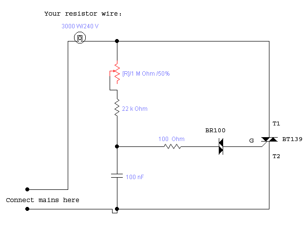
In place of spending alot of hard earned cash on an expensive power regulator, I made my own. Capable of regulating 16 Amperes (3.5 KW on 240 V), it will suffice for most things.

It can be made with under 10€ electronic parts.


Schematic:


First tests with it seem very promising.
A RBF heating mantle will be my first project :D

BrAiNFeVeR - 1-3-2005 at 10:49

An action shot of the above construction:


Notice the old cpu cooler the BT139 triac is mounted on.

The setup is mounted on a simple piece of wood now, but this is only to show the simplicity and size of the cirquit.

chemoleo - 1-3-2005 at 19:20

And the BR100 and BT139 thyristors (??) are some we can buy from any electronics supply?

Just to point out, www.conrad.de sells power regulators for cheap too. But I like the idea of making one yourself. Nonetheless, I think the ultimate quest of making your own electrical furnace is that of ensuring proper insulation, proper heat-wire selection, and proper design. Not to put you down at all - please understand that priorities in this forum lie within the chemistry, material chemistry, and so on; rather than electrics and electronics, or electrotechnics.

Please post though where you get those thyristors from (just searched Conrad, but couldnt find them). It's definitley cheaper than buying a full-scale power regulator altogether.

BrAiNFeVeR - 2-3-2005 at 14:35

Any electronics shop should have these components.
I got mine from a Velleman shop.

Most components are dirt cheap (a few cents), only the printboard, variable resistor and BT139 triac where a bit more expensive.
About €3 for the print, €2 for the varistor and €2 for the triac. The rest of the part cost is less then €1.

The complexity for the scheme is low enough to be feasable to make for amateurs in the electronic science, and can (as you see) make a big difference in price.
Money that could be better spent on some quality glassware :)

Conrad has them too:

BrAiNFeVeR - 5-3-2005 at 04:37

Clicky: conrad site BT139

Though they are more expensive then the shop I went to ...

Datasheets can be found on Datasheetarchive.

[Edited on 5-3-2005 by BrAiNFeVeR]

The_Davster - 30-11-2005 at 19:59

I have been thinking of building a small furnace recently. I got this (to state what it says on the case) "variable transformer" that weighs around 15 lbs out of my university junkheap. It is rated for an input of 120V and an output of 0-140V at 7.5 A. It has an 8A fuse built in. I tested it on a lamp and it works to dim it(just checking to make sure it is still operable). Will this work as a power regulator for a small furnace?

If it does then by v=IR, R=V/I=140V/7.5A (am I using the right amperage here? the rated one of the supply and not what the electrical 120V line is rated for?) R=18.6666666ohms needed in the coil.
Assuming 0.5410mm kanthal D wire resistance is 5.8936 ohms per meter, then I need 3.17m of wire.

Of course I could use much less wire if I wanted a very small "furnace" for the heating of a small crucible, and just never turn the power relulator to full, right? Just never exceed a maximum voltage on the regulator based on calculations from the length of the wire?

Magpie - 30-11-2005 at 20:36

Your calculation and assumptions seem right to me, although I have never built a furnace. The max power would be 7.5 x 140 = 1050w. Does that agree with the nameplate max wattage?

I believe for most wires resistance goes up with temperature so a cold wire should draw the most amps & power.

Mr. Wizard - 30-11-2005 at 21:34

The variable autotransformer is also called a variactor, and they were very popular before solid state controllers, and switching power supplies became cheap and popular. The weak link in the variactor is the limit on how many watts you can pull out of it, and the sliding contact may get hot, burned or otherwise screwed up, especially under heavy loads; like furnace heating elements. Keep your nose near the unit and if it starts to smell hot, turn it off. The solid state stuff is really better for this. If you use a variable auto transformer, don't use it near it's upper power limit. I have a 5KW unit as big as a car wheel, and someone had toasted the sliding contacts before I got it!

The_Davster - 30-11-2005 at 21:44

Thanks for the info, I do not plan on building a large furnace anyway, I just need something to melt small ammounts of powdered antimony, to consolidate it into any other form, and likely for melting other metals as well. However, for such a small use, it would be a shame to have to buy so much wire from resistancewire.com, anyone have a source for smaller ammounts?

http://www.used-line.com/c4452597s1424-Ohmite_VT8.htm
This is the one I found, it just needs a new cord(I found it without one). 150$ piece of working equipment for free...wow...:o

neutrino - 1-12-2005 at 03:25

Have you tried eBay for smaller amounts?

IrC - 1-12-2005 at 07:53

Recently I replaced the element and all the bricks in my 117 Vac HB64 kiln, ordering the parts from Olympic. I decided to build a tube furnace around my 1 inch quartz tubing using the old bricks and crafting them into the shapes I needed. For the element, the cheapest way I found was to just buy a second replacement element for the original kiln, as it was only 25 dollars. If I were you, this is the way to go, since all needed calculations concerning resistance and current are already done for the element to run a long time without burnout. The URL is http://www.kilns-kilns.com/ . The element comes with new Kanthal pins and 2 crimp terminals, all you need is a controller. I bought a replacement infinity controller as that was also only 25 dollars. Worked out great. For items like variacs Fair Radio Sales in Lima, Ohio is a good place to look.

You might consider replacing the copper/graphite brush in your variac, the local place that rebuilds starters and alternators is perfect if you bring your old one and just do a little machine work to get dimensions correct. While I already have 1KVA and 5 KVA variacs, I found the infinity controller was vastly superior (and much lighter and smaller!).

Mr. Wizard - 2-12-2005 at 09:49

Thanks for the suggestion to use the copper/graphite brushes from an alternator repair kit. I could have used the brushes from an old starter too, as they are big and easy to work on, and have the advantage of having a heavier braided copper leads already attached. That's what I did to fix it. It's a big old boat anchor, awaiting a suitable project.

Magius - 8-12-2005 at 19:30

Quote:
Originally posted by IrC
Recently I replaced the element and all the bricks in my 117 Vac HB64 kiln, ordering the parts from Olympic. I decided to build a tube furnace around my 1 inch quartz tubing using the old bricks and crafting them into the shapes I needed. For the element, the cheapest way I found was to just buy a second replacement element for the original kiln, as it was only 25 dollars. If I were you, this is the way to go, since all needed calculations concerning resistance and current are already done for the element to run a long time without burnout. The URL is http://www.kilns-kilns.com/ . The element comes with new Kanthal pins and 2 crimp terminals, all you need is a controller. I bought a replacement infinity controller as that was also only 25 dollars. Worked out great. For items like variacs Fair Radio Sales in Lima, Ohio is a good place to look.

You might consider replacing the copper/graphite brush in your variac, the local place that rebuilds starters and alternators is perfect if you bring your old one and just do a little machine work to get dimensions correct. While I already have 1KVA and 5 KVA variacs, I found the infinity controller was vastly superior (and much lighter and smaller!).


Whoa whoa, what?! Surely it can't be that easy.

IrC, are you saying that you built a fully functional furnace (Abit with 1" quartz tubing as the crucible) for 50$ using only the infinity controller to vary the current and the purchased heating element? Care to enlighten us (with pictures if you have the time) on your particular set up? Does the heating elemtent come in a preset design/cut length to fit with the powersupply from the infinity controler? Does the controller let you vary the amps and thus heat out put? I suppose it must, kilns arn't always fired at max temperature...

That just seems too easy. Perhaps I'm missing something?

On another note, I have been doing alot of reading on furnaces, and came across the idea of a reverbatory furnace from Here

This looks nifty, especially if its electric instead of propane fuled. The main advantage I see is not having to deal with a cruicible, while a disadvantage is that brass/bronze/zinc could never be cast as the Zinc Oxide fumes would probably damage/destroy the heating element. It could be built easily enough, is usefully for casting ingots, and with an little inginuity, could probably have a base with a jack in it to help pour just like a cruicible would. See this picture for a rough idea of what I'm talking about

IrC - 17-12-2005 at 17:40

Since the U2U reply does not work right with my browser it is easier to answer here, plus then others gain from any information given. I really don't like to answer questions like this in a U2U since it does not help the board. So my reply:

Quote the U2U from Magius

"IrC, I posted in the Electric Furnace thread a while back, care to reply? I also have some more questions on your post. The infinity controller you mentioned, does it look something like this? (http://cgi.ebay.com/Paragon-PCB-1-Power-Control-Infinite-Swi...) And if it does, doesnt that look an aweful lot like this? (http://cgi.ebay.com/ws/eBayISAPI.dll?ViewItem&item=75723...) For 25$'s though, I'll probably just buy it from the site you mentioned. Now as for wires, do you know the specifications for resistance, heat expansion, max temp ect? You said that all the calculations were already done for you, but I must be missing something, becuase some of the kilns require 2+ heating elements to work, how does the kiln pull 2x electricity to get up to the same temperature? Which leads me to my next question: How hot can the bricks get before they break down?

On this site ( http://www.baileypottery.com/) it lists some of its bricks as having a max temp of 3000F(1650ish C) but the site is unclear as to how much they cost(5.50 a brick?!)"
---------------------------------------------------------------------
I imagine the controller is the same, just minus the box and wiring, etc.. I do not know the specs on the heating element, as far as I know they don't state it at Olympic. It was just a replacement element for a 117 Vac kiln, so therefore they had cut the length correctly for the HB64, the kiln I was talking about. It draws around 15 amps, and the controller is the replacement unit for this model. On the controller question, it is just the controller by itself for $25, as it goes into the box on the side of the kiln. A kiln using two elements is likely wired for 240 Vac using two 117 Vac single elements. Don't ask me why 117 and 240, it is just the terms used, where 117 is the so called "national average" of voltage for the power grid in the U.S. (I know this as I asked a lineman about it once), likewise when it comes to the secondary voltage of a pole transformer the term 240 is the most often one used.

I am sure around the country the line varies from 110 (rural) to 122 (city) so the confusion as to 220 or 240, etc., but I digress.

Around 2,000 F is the highest safe temperature before the element gets wasted, but I have learned that two things affect this more than other factors. One is when the wire is installed to correctly stretch the coils so there in not an area where the loops get too close together (this was the point in my kiln where the element burned in two). Also, the speed at which operating temperature is reached is critical, no more than 100 degrees F per hour increase will give you long life, VS going from say 500 degrees F to 1800 degrees F in under 60 minutes. This factor is also the same for the bricks as far as cracking and failure of the refractory goes. If you are impatient and zoom your kiln up to 2,000 degrees F in a real hurry expect to see catastrophic failures quite often in many areas. Likewise opening your kiln door and letting cold air rush in is a death blow to both the elements and the refractory.

As to the question "some kilns require 2+ heating elements to work, how does the kiln pull 2x electricity to get up to the same temperature?", You need more heat source for a kiln with a larger interior size, and the factor of pulling twice the current to get up to temperature only applies to the area heated. At least in terms of normal kiln design that is, or in other words you could build a kiln with two elements spaced closer together but I think failures would be an issue, as well as power efficiency. It looks to me like the going method is to have one channel per brick for the elements to go through. So a kiln two bricks high would have two rows of element(s). This could be one long one or two shorter ones in series, or whatever variation depending upon kiln size and voltage. Really this is all about amps since kiln manufacturers are usually thinking of the average home power source, VS some custom setup in a factory or whatever.

The number of elements to get up to temperature is not important from the viewpoint of your question about twice the electricity, etc., as the elements are cycled on and off. By this I mean two elements for the same internal area likely would be on only half as much. Maybe this is a good idea for a fast rise in temperature while still keeping long element life but I assume the refractory failure rate would limit these things anyway. As to the infinity controller obviously you will burn it up if you overload it (amperage wise), it is common sense to properly consider each and every little point in your overall kiln design.

When you are designing a kiln first you need to know the maximum temperature to choose the right refractory. If I wanted a 2,500 F kiln it makes sense to find a 3,000 F brick. Then size inside. I would want no more than two and a half inches of distance between heating elements, so if I was using 3 inch brick stacked two high then a single channel down the center of each one would be great. Now overall area. How many inches of total length is needed for the elements to go all the way around inside, for each row. What is the resistance per foot for the elements I will use? What is the amperage I wish to have as a maximum limit for my wall outlet? If you say 20 amps at 117 Vac then I would say redesign the kiln for 240 Vac and use 10 amps. Easier on the house wiring so to speak. Under no circumstance would I want a design which needed some form of ballasting. Every kilowatt hour being used is going to go into heating bricks in any kiln I design.

This may mandate choosing a different heating element to go the same distance around the inside while staying within design parameters such as amperage draw, and how many amps can the controller handle, and so forth. Consideration should be given to the temperatures expected and what can the elements handle, and in my case how well do they withstand chemical fumes is important. I just love bringing a big dish of Lanthanum Carbonate up to 2,000 degrees F for two hours and pulling out the dish with this little bitty pile of Lanthanum Oxide. Call me weird but this is more fun than buying the oxide. Ok, so being real I found a deal on the carbonate and could not find any decent source for the oxide. To be honest until I repaired my first kiln, and then designed my first kiln, I had no idea what a really complex engineering challenge the whole thing is to have something that will do all I need combined with extremely long life and absolute safety. Those guys at Olympic must really be on the ball in the engineering department, I have been very impressed with my little kiln since the day I bought it. Of course the base is the only original part left and I even redesigned that to give more bottom support. In all fairness to them I don't think they had mad science in mind. I like to get from room temperature to two grand in two hours, while baking a dish full of chemicals. Who knew?

Of course my life was made much better when a member here introduced me to the concept of ITC-100 for the bricks and ITC-213 for the heating elements! I used to get burned if I touched the top of the kiln while it was up to 2,000 F. After coating ITC-100 on the inside, now I can actually hold my hand on top a few seconds without discomfort. I can only guess how much more thermally efficient this is, also the elements are cycling on only a third as much as they used to. ITC-213 coated on the heating elements protects from burnout as well as protecting them from chemical fumes inside the kiln. The first time you fire a kiln up you should go through a conditioning process to drive every iota of moisture from the refractory. Rather than write a novel I would add there are many good sources online for such information.

hinz - 20-12-2005 at 09:54

I've just finished my own furnace:cool:
Here is the link for the pictures.

http://www.picturetrail.com/gallery/view?p=999&gid=88977...

As you can see, It's made of an welded steel frame with heat resistant stones inside. The heating wire is wrapped around some ceramic sticks to give stability to the heating wires at high temperature. The ceramic sticks are holded by cramps made of Kanthal wire which are jamed into the heat resistant stone. The isolation is mineral wool.
At the beginning I heated the oven with 220V. At 220V the furnace had 220V*2 coils*6A=2600W which wasn't enough. It only went up to appr. 700°C. So I hoped that the fuse would hold and connected the furnace at 380V. Surprisingly the fuse hold 380V*2*10,5A=8200W and the furnace went up to 1150°C after only 5 minutes.
I don't know yet why the fuse hold it, because 380V are 3phases and I had to connect one phase to both two coils and one coil pulls 10,5A but my fuse is only rated for 16A.
Now I need to build a temperature controller and then I'll try to reduct some phosphate to white phosphorous ( big scale of course) :)
All the temperatures I measured with an IR radiation thermometer.


[Edited on 20-12-2005 by hinz]

Mr. Wizard - 20-12-2005 at 17:08

Hinz, I worry about a furnace with a wood outside cover. After a few hours of heating the temperature on the outside of the insulation will rise, and anything over 100C will lead to slow charring of the wood. I know it will take a while, but that heat has to go somewhere. You should IMO, put some sort of non combustible cover such as sheet metal or a metal can. The inside temperature will be determined by how much heat is being put into the furnace compared to how much leaks out through the insulation. One other thing I would change is to reduce the resistance of the heating elements by wiring it in parallel.
Instead of L1~~~~~~~~~~~~~~~~~~~~L2 where L1 is one side of the 220 mains and L2 the other; I would try L1~~~~~~~~~~L2~~~~~~~~~~L1 where the L1 connections are connected. This will lower the resistance of the elements and allow you to get by without using the higher voltages and 3 phase, but that is only a matter of choice. It will allow more amperage without the higher more dangerous voltages.
Watch that wood.

NJF - 23-12-2005 at 16:31

Have any of you guys with furnaces had a serious go at making phosphorus yet? I recently inherited an electric kiln which I think should be hot enough (pics in the phosphorus production thread in the general section), although I haven't powered it up yet. I'm just wondering what happened if anyone did, and whether or not their houses are still intact?

The_Davster - 26-12-2005 at 13:45

Yay, I got an old waffle iron out of the trash today with about 1m(when coiled) of around .4mm resistance wire. As soon as I can get the refractory ingredients I will be able to make my micro-furnace.:)

The_Davster - 7-1-2006 at 14:17

Well the furnace is done, it is currently drying at 40v outside. It turned out OK, not as good as I had hoped due to the following reasons:
-I used a big thick wooden dowel to make the hole, removing it took me several hours with a hammer, chisel and power drill. As a result some of the indents for the resistance wire were badly damaged.
-I used 5 year old cement in the refractory
-Ended up making 2 batches of refractory, the second perhaps a bit too fast as I did not make enough the first time.

EDIT: Cost to me: around 20$ I had most things lying around except bentonite and the nuts and threaded rod. And I keep blowing the 8A fuse in the variable transformer:P

EDIT: All galvanized parts(threaded rod and nuts, not the paint can it is in) that will be exposed to high temps were soaked in HCl until major bubbling stopped, hopefully most of the zinc was removed this way.


[Edited on 7-1-2006 by rogue chemist]

furnace1.JPG - 195kB

hinz - 7-1-2006 at 15:56

Nice furnace rogue chemist.
How do you manage your temperature controller. I always measured the temperature of my furnace while heating to prevent overheating of the coils. As much I know, most Kanthal heating alloys are melting at 1450-1500°C and are rated for 1300-1400°C at continous operation. (150°C is not that much at high temperature) The resistance doesn't increase much at high temperature. At the Kanthal's (http://www.kanthal.com) homepage are some good informations about it.

I've ordered a thermocouple and I'm learning how to programm an AVR at the moment, because I don't like to spent much money on a controller. (If I would do so, I could also waste my money for an used furnace at ebay)
My idea is to connect the thermocouple on an operation amplifier to amplify the few mV (here is a good table for Type N Thermocouples http://www.rescal.com/type%20n.htm)up to 5V at 1533°C. Then I connect the amplified output to an 9bit A/D converter of an AVR Mega8, this gives (9bit are 512-1) 511*3=1533°C.Then I only have to programm my AVR that "he" switches off the furnace at a defined point and swiches it on if the temp. falls under a defined point. The power relais and the AVR-power relais interface (100W amplifier) and the LED-Display are already finished but I've still some problems with the AVR software.

Mr. Wizard
Thank's for your comment, I've coated the top and both sides with sodium silicate liquid glass to prevent burning of the wood.I'll see how hot it gets and then I'll maybe cover the wood with aluminium foil and a second thin layer of stone wool to prevent that hot gasses can come in contact with the wood.

[Edited on 7-1-2006 by hinz]

The_Davster - 7-1-2006 at 17:32

Quote:
Originally posted by hinz

How do you manage your temperature controller.


The fuse blows at 8A, or whenever I turn the power up to 130-140v. If the furnace doesent reach the temp needed to melt Sb and Al, I guess I will switch to a higher amp rated fuse or if I am feeling crazy...just bypass the fuse...Let the beakers limit me instead:P.

EDIT: I am probably kidding about bypassing the fuse...probably...

EDIT: The lid for the furnace is about 1.5" thick, I put a metal strip around it, to hold a handle in place. The metal strip was found in a construction site, but the refractory should keep any heat away from it if the metal contains zinc...I hope.

Also, the furnace is currently running at around 60v, nice glowing coil inside, and steam coming out of the furnace like mad.

Any zinc that was missed by the acid wash should hopefully be burnt out while the furnace is running outside, as the furnace will ideally be used indoors when the drying is complete.

[Edited on 8-1-2006 by rogue chemist]

The_Davster - 7-1-2006 at 21:42

AARG....the coil melted through...and I only have one more left. Perhaps I should just break down and buy a spool of it from resistancewire.com.

Waffle iron resistace wire just does not hold up too well I guess.

garage chemist - 8-1-2006 at 15:03

Have you considered buying a small furnace for pottery/enamelling/ceramics from ebay?

I searched for "brennofen" in german ebay and got some interesting furnaces, some of them small and with an affordable price (below 100 Euro) but suitable for very high temperatures (usually 1200°C, and none of them under 1000°C).
When having little time and lack of construction skills, this is a good alternative to a home- built furnace for things like making cyanides from cyanates, melting metals and making phosphorus.

MetalCastr - 5-3-2006 at 16:22

Nice stuff. Check out www.backyardmetalcasting.com for furnace designs and help,

alsohttp://www.dansworkshop.com/ he built an aluminum melting 240V furnace. He also sells instructions, which I bought, and they are very detailed. I am thinking of making this furnace soon.:cool:

IrC - 6-3-2006 at 15:01

Found this source of graphite electrodes:

http://www.geselectrodes.com/specialtygraphite.htm

MetalCastr - 17-3-2006 at 08:56

I recently bought that controller from payne engineering. I think they meant "pain" engineering because of the 111 dollar cost total for thier 240V controller:P

To run my 240V furnace, I had to make a 240V extension cord out of 1 plug, one receptacle, and 10 gauge wire ( had to wrestle it) to get a 240 supply outside of the garage from the dryer outlet. MY controller came with a 15A fuse so it can handle moderately heavy loads.

I recently rewound the secondary coil an old microwave transformer with 12-guage wiring hoping to power my furnace with tons of amps from a 120 supply, this failed. Apperently the windings deliver enough current but not enough volts to get across the coil, you could hold it with your bare hands (it was only about 100 degrees).

What happened: 120 In, 27 out. I can't measure the amps because my multimeter only goes to ten.
Mabey I wil make a small spot welder with it or something.

Don't overload the 15 amp rating on the 240 controller. I burned mine out, and had to manually bypass the fuse

[Edited on 18-3-2006 by MetalCastr]

12AX7 - 19-3-2006 at 04:38

Quote:
Originally posted by MetalCastr
and had to manually bypass the fuse


:o:o:o:o

MetalCastr - 25-3-2006 at 13:46

Not to worry, I have it on a heatsink with a small blower fan. Thing doesn't even get warm. Oh yes, I've found a lower cost website for good SCR controllers

http://www.thermalinc.com/power/tbp.htm

[Edited on 25-3-2006 by MetalCastr]

I have a question. Is a Router speed control the same thing/circuitry as a lamp dimmer?

[Edited on 25-3-2006 by MetalCastr]

12AX7 - 25-3-2006 at 14:02

Yeah. Most variable speed power tools have a "universal" motor.

Tim

Cloner - 26-3-2006 at 06:49

In the case of using any kind of resistance wire in a coil, what will the impedance be at 50 Hz? I kind of forgot how to calculate, but remember there was a formula for the effective resistance for coils and capacitors as a function of the frequency.

12AX7 - 26-3-2006 at 09:29

That's called reactance, and depends on the inductance, which depends on the turns and whatnot. The equation you are thinking of is probably something like L = N^2 + R^2 / (9R + 10X), where N is turns, R is radius, X is length and L is in microhenries or something. (Seems to me there should be a constant in there, too.) Eh, Google it.

Unless you're cooking an utterly massive chunk of ferrite (which is a ceramic :) ), inductance is negligible.

Tim

Cloner - 27-3-2006 at 01:10

Yeah well I have been googling for this, it's that I do not trust what I found. In fact, I know a book which is somewhere in my basement which describes it. Finding that book, though, isn't as easy as it seems:( Assuming that nichrome has almost the susceptibility of vacuum, I still get a significant inductive effect on 50 Hz from the googled formula...

But if everyone else simply uses AC and has no problems whatsoever, then the correct formula isn't so important:D

IrC - 27-3-2006 at 10:18

I would listen to Tim, the resistance alone is your only consideration here. The inductive reactance is such a small part of the equation it does not even matter. The current flow change due to this parameter is so small you are not likely to even measure it. Worry about the actual ohmic resistance of the wire and forget any inductive effects.
 Pages:  1