Rainwater
National Hazard
   
Posts: 925
Registered: 22-12-2021
Member Is Offline
Mood: Loving every second
|
|
Electrode shapes
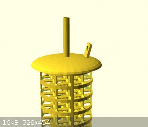
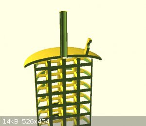
attached are some concept images
my question is
How important is the shape of the electrodes in a simple cell?
Would the efficiency gained be worth the time to make such a shape.
I know ultimately that efficiency is greater when voltage is low and current is high.
Current is high when resistance is low.
Resistance is low when surface area is high and spacing between electrodes is low.
When considering the shape of the electrodes i realized that i need to account for a few things. Listed in no particular order (please mention
anything i miss)
1)The electrolyte at the surface of the electrodes may become depleted and the reaction will slow until new solution diffuses in to take its place.
2) The current density at different sections of the shape.
3) Thermal density at different sections of the surface
4) Precipitation/off gassing of products/byproducts on the electrode itself.
then there are things which I want.
I want my electrode to
- be easy to attach my power supply to.
- air tight seal into the container i am using.
- have drain/source path for electrolyte and off gassing
- be precision fitted to its mate to minimize distance between the electrodes
I am debating of 3d printing and casting the entire thing in lead then converting it into PbO2 via sulfuric acid electrolysis.
im also requesting comments for a good way to force circulation of the electrolyte. without contaminating the products.
For this I guess i should include information on my desired products.
currently H2SO4 via a diaphragm cell, with epsion salt as the starting material.
And NaOH via reduction cell, with baking soda as the starting material.
I would like to create more than one set of electrodes at a time so it would be great if I could use one material which would serve in both types of
solutions.
[Edited on 24-12-2021 by Rainwater]
|
|
|
mysteriusbhoice
Hazard to Others
  
Posts: 477
Registered: 27-1-2016
Member Is Offline
Mood: Became chemistry catboy Vtuber Nyaa
|
|
if you want a maximum efficiency H2SO4 production cell then your best bet is a multi compartment membrane electrolysis cell divided into sections
where you use planar electrodes and alternating cathode and anode chambers where if you want a feed source you can make it so that you have Na2SO4 as
the working fluid which will form H2SO4 in the anode chamber until it reaches 35% before its drained then the NaOH of the cathode liquid is
intermittently widthrawn into a mixing chamber containing MgSO4 to react and form Mg(OH)2 and Na2SO4 again and thus Na ions are the catalyst here.
for membranes if you plan for best yield just use neutral PVC glue on cleaning cloth/fiberglass which was treated in 4 molar NaOH for 12 hours to make
it more permeable.
electrodes should be plates not meshes unless you want to conserve materials and anodes can be lead which is oxidized.
Overall membranes will allow more current draw then using ceramic pots as a single membrane 2 compartment cell ive run up to 10 amps at 8 volts now
imagine running like 4 membranes on 40 amps.
provided you can cool the liquids down this can indeed be doable.
|
|
|
mysteriusbhoice
Hazard to Others
  
Posts: 477
Registered: 27-1-2016
Member Is Offline
Mood: Became chemistry catboy Vtuber Nyaa
|
|
To circulate the liquids are either to use 2 holding tanks and 2 diaphragm pumps to pump the liquids in the seperate chambers one for the H2SO4 and
other for recirculating NaOH to feed into MgSO4 this is for semi continuous fed batch operations.
For batch mode operation if you want simple agitation of the liquids to prevent the formation of concentration gradients around the electrodes caused
by plug flow operations then you can just use aeriators for aquariums.
|
|
|
Rainwater
National Hazard
   
Posts: 925
Registered: 22-12-2021
Member Is Offline
Mood: Loving every second
|
|
Is the concentration of 35% a point were production slows or stops?
How flexible is the membrane after it is completed?
Do you have to form it into shape before treatments.
Im currently using a 12mm thick taracotta saucer from the hardware store. It fits perfectly inside 2 90 degree 3.5in pvc fittings. It does get quite
hot (60c) but so far has survived over 2000 hours @ 32volts max 0-5 amp current source.
When generating NaOH i follow the procedure
I monitor the wattage (15-150watts) over time. When the cathode chamber is just distilled water I add 50mL from my previous batch to jumpstart the
reaction. i write down the wattage. As the cell runs the wattage goes down. When the wattage begins increasing i refresh the anode solution. Then
repeat. Each time it takes longer for the wattage to begin increasing. I have done various control experiments and calculated yield vs refresh counts
as well as hours ran. After 3 refills of the anode compartment it is time to remove the solution from the cathode.
Im looking forward to following your video instructions and comparing the results against the data ive already collected. If the cloth membrane can
withstand the abuse i could wrap it around the electrodes and decrease the distance between them.
|
|
|
mysteriusbhoice
Hazard to Others
  
Posts: 477
Registered: 27-1-2016
Member Is Offline
Mood: Became chemistry catboy Vtuber Nyaa
|
|
Quote: Originally posted by Rainwater  | Is the concentration of 35% a point were production slows or stops?
How flexible is the membrane after it is completed?
Do you have to form it into shape before treatments.
Im currently using a 12mm thick taracotta saucer from the hardware store. It fits perfectly inside 2 90 degree 3.5in pvc fittings. It does get quite
hot (60c) but so far has survived over 2000 hours @ 32volts max 0-5 amp current source.
When generating NaOH i follow the procedure
I monitor the wattage (15-150watts) over time. When the cathode chamber is just distilled water I add 50mL from my previous batch to jumpstart the
reaction. i write down the wattage. As the cell runs the wattage goes down. When the wattage begins increasing i refresh the anode solution. Then
repeat. Each time it takes longer for the wattage to begin increasing. I have done various control experiments and calculated yield vs refresh counts
as well as hours ran. After 3 refills of the anode compartment it is time to remove the solution from the cathode.
Im looking forward to following your video instructions and comparing the results against the data ive already collected. If the cloth membrane can
withstand the abuse i could wrap it around the electrodes and decrease the distance between them. |
32 volts is really high lots of wasted power.
for membranes they operate at decent current at around 6-8 volts and at 35% thats when production slows down and current begins to fall as it reaches
equilibrium.
The membrane needs to be mounted in frames because its very flexible and you cannot have any leaks or water pouring from the sides of the container.
For high rate of production you want low voltage and high current at about a current density of 80ma/cm^2 or greater and voltage would be 6-8 volts.
When the membranes are fresh and unpolarized they will start off with very very low current but once polarization occurs the current rises fast.
My video is on Cation exchange membranes and if you want Anion membranes for feeding MgSO4 in the cathode chamber then you must replace the citric
acid with aspartic or glutamic acid so it can allow sulfate ions to pass through further treatment with a methylating agent increases anion
permeability further but this is optional.
|
|
|
Fulmen
International Hazard
    
Posts: 1720
Registered: 24-9-2005
Member Is Offline
Mood: Bored
|
|
Even though I like the idea of a lost PLA cast electrode, any cost/benefit analysis would favor simple geometries like sheets or tubes. The cell
should be designed with convection in mind. Any gas production or heating of the electrolyte will reduce the density between the electrodes, this
should be enough to provide circulation.
We're not banging rocks together here. We know how to put a man back together.
|
|
|
Rainwater
National Hazard
   
Posts: 925
Registered: 22-12-2021
Member Is Offline
Mood: Loving every second
|
|
The voltage is controlled by my power supply. It maxes out at 32. Usually when i start with fresh solution(50mL of jumpstarter) the current locks in
at 3-4 amps with a voltage of 32 Within a few hour the voltage drops to less than 16. I only generate about 10g a day. My cell is less than 10-15%
efficient but my triation techniques are most likely a big cause of loss.
I also use a 100mL graduate cylinder and test the density which gives me better looking results( 20-25%) but again is only as good as the measurements
i can take
Santa will be working up some ideas on increasing the membrane area as well as simplify the geometry
|
|
|
mysteriusbhoice
Hazard to Others
  
Posts: 477
Registered: 27-1-2016
Member Is Offline
Mood: Became chemistry catboy Vtuber Nyaa
|
|
Quote: Originally posted by Rainwater  | The voltage is controlled by my power supply. It maxes out at 32. Usually when i start with fresh solution(50mL of jumpstarter) the current locks in
at 3-4 amps with a voltage of 32 Within a few hour the voltage drops to less than 16. I only generate about 10g a day. My cell is less than 10-15%
efficient but my triation techniques are most likely a big cause of loss.
I also use a 100mL graduate cylinder and test the density which gives me better looking results( 20-25%) but again is only as good as the measurements
i can take
Santa will be working up some ideas on increasing the membrane area as well as simplify the geometry |
get like a 12V 20A PSU or something computer PSU would do far better with proper membranes in place it will draw loads of current.
|
|
|
unionised
International Hazard
    
Posts: 5127
Registered: 1-11-2003
Location: UK
Member Is Offline
Mood: No Mood
|
|
Quote: Originally posted by Rainwater  | attached are some concept images
my question is
How important is the shape of the electrodes in a simple cell?
Would the efficiency gained be worth the time to make such a shape.
I know ultimately that efficiency is greater when voltage is low and current is high.
Current is high when resistance is low.
Resistance is low when surface area is high and spacing between electrodes is low.
When considering the shape of the electrodes i realized that i need to account for a few things. Listed in no particular order (please mention
anything i miss)
1)The electrolyte at the surface of the electrodes may become depleted and the reaction will slow until new solution diffuses in to take its place.
2) The current density at different sections of the shape.
3) Thermal density at different sections of the surface
4) Precipitation/off gassing of products/byproducts on the electrode itself.
then there are things which I want.
I want my electrode to
- be easy to attach my power supply to.
- air tight seal into the container i am using.
- have drain/source path for electrolyte and off gassing
- be precision fitted to its mate to minimize distance between the electrodes
I am debating of 3d printing and casting the entire thing in lead then converting it into PbO2 via sulfuric acid electrolysis.
im also requesting comments for a good way to force circulation of the electrolyte. without contaminating the products.
For this I guess i should include information on my desired products.
currently H2SO4 via a diaphragm cell, with epsion salt as the starting material.
And NaOH via reduction cell, with baking soda as the starting material.
I would like to create more than one set of electrodes at a time so it would be great if I could use one material which would serve in both types of
solutions.
[Edited on 24-12-2021 by Rainwater] |
To a fair approximation that electrode looks like a cylinder and, due to essentially "faraday shielding" of all the complicated parts inside it will
do nothing.
A cylinder of lead sheet would work better.
|
|
|
Fulmen
International Hazard
    
Posts: 1720
Registered: 24-9-2005
Member Is Offline
Mood: Bored
|
|
I agree, it would be impossible to keep the current density anywhere near uniform, and worse you can't even guesstimate the peak density.
We're not banging rocks together here. We know how to put a man back together.
|
|
|
Rainwater
National Hazard
   
Posts: 925
Registered: 22-12-2021
Member Is Offline
Mood: Loving every second
|
|
Sounds like simpler is better. that first one did look cool.
I guess my next question is how close is too close.
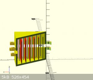
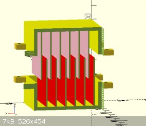
for example, if I stacked sheets (see pictures) on one top of the other with a membrane interwoven how much room should be allowed for the electrolyte
to flow freely?
[Edited on 26-12-2021 by Rainwater]
"You can't do that" - challenge accepted
|
|
|
mysteriusbhoice
Hazard to Others
  
Posts: 477
Registered: 27-1-2016
Member Is Offline
Mood: Became chemistry catboy Vtuber Nyaa
|
|
depends on your constrants for max efficiency you want like 3mm to 4mm distance between either side of the membrane and the electrode.
the feed lines would alternate between each cell where one compartment would be an anode chamber and the other a cathode chamber and in the 2 holding
tanks you would start with a dillute solution of Na2SO4 in the anode chamber loop and saturated MgSO4 solution in the cathode chamber loop.
each of these cell compartments would have 1 input and 1 output and the cell is ran until the contents of the anode chamber loop's holding tank
reaches like 20% to 30% H2SO4.
The only real problem I see with a semicontinuos membrane setup using MgSO4 as the feed is that you will have to remove the product Mg(OH)2 or else
risk blocking the pipes.
Either that or you can make it so that each cathode chamber is filled with MgSO4 slurry or wet crystals and only circulate the anode chamber liquid
which is also an option but it would reduce efficiency by a bit and you would have trouble dissasembling the cell everytime because I take it that
this cell is meant to be assembled once and never dissasembled till like 6 months later.
The membranes require frames btw and maybe some sort of rubber gasket on the frames so they do not allow any leakage of the 2 solutions in seperate
chambers through the sides as that is a real efficiency killer.
|
|
|
Rainwater
National Hazard
   
Posts: 925
Registered: 22-12-2021
Member Is Offline
Mood: Loving every second
|
|
Quote: Originally posted by Fulmen  | | any cost/benefit analysis would favor simple geometries like sheets or tubes. The cell should be designed with convection in mind.
|
agreed sir.
Now i'm thinking a long copper tube. with the anode inserted into it.
the anode wrapped in the diaphragm material again with a lead anode running the length of the tube.
what effect will the membrane being in physical contact with the anode or cathode have?
The white rings on the anode are just there to spacing the membrane
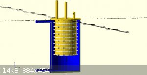
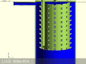
I might scrap the entire idea of a custom anode, maybe just using stock rods and copper tubing, then custom making some fittings to connect it all
together and space it out.
[Edited on 26-12-2021 by Rainwater]
Attachment: anode_gas_adapter.scad (6kB)
This file has been downloaded 277 times
"You can't do that" - challenge accepted
|
|
|
mysteriusbhoice
Hazard to Others
  
Posts: 477
Registered: 27-1-2016
Member Is Offline
Mood: Became chemistry catboy Vtuber Nyaa
|
|
if the anode is in contact with the diaphragm its not an issue provided the flow is annular aswell which means it would be good to have the cathode
chamber on the center and the anode chamber to be annular. With the flow area being annular the flow condition will pull the sulfate ions away from
the anode and allow for good flow distribution on all sides and not accumulate in the middle where there is less pressure drop.
The cathode chamber can be one large steel or copper rod/pipe around a membrane and slurry or MgSO4 solution being kept or pumped around inside and
thus this makes a good tubular H2SO4 generator.
|
|
|
Fulmen
International Hazard
    
Posts: 1720
Registered: 24-9-2005
Member Is Offline
Mood: Bored
|
|
Quote: Originally posted by Rainwater  |
I might scrap the entire idea of a custom anode, maybe just using stock rods and copper tubing, then custom making some fittings to connect it all
together and space it out. |
This would be my first approach as well. There is only so much you can learn without getting your toes wet.
Make a simple, low effort setup. Test it and try to model the results. Once you've dialed in the cell you can build a more permanent setup based on
real experience.
We're not banging rocks together here. We know how to put a man back together.
|
|
|
Rainwater
National Hazard
   
Posts: 925
Registered: 22-12-2021
Member Is Offline
Mood: Loving every second
|
|
I was just using a lead bar ( 1.5in x 8in long ) and a copper bar about the same size tied to the side of the pvc fitting.
So i cast the cathode in copper with a 3in disk connected to a 8in rod. bent it to fit the plumbing sweep and placed it up against my ceramic
diaphragm.
The same with the anode but in lead.
Great improvement ... Happy happy ...
not my best casting but it is working.
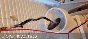
the baking soda solution appeaser to be oxidize the anode like H2SO4.
power supply before changing out the electrodes with a 8-9% solution
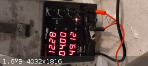
After changing them.
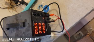
Thanks everyone. this should get my production up to something i can crystallize out within a reasonable amount of time.
1.5 L capacity I think I could reach 25-30% concentrations within a week.
then if I crank up 10 amps.
so 100% efficiency would be what, about 14g an hour.
Is it just 1 e- for the production of NaOH .... ill read the section in my text book again. sorry. thinking out loud. so
Next question would be.
Should I keep refreshing with saturated solution or leave undissolved solids in the anode chamber?
Hoping that the solids will dissolve and replenish the solution as the reaction progresses and not start converting my PbO2 into some form of
carbonate.
I had problems with this with my other anode.
I figured it was do to the extra voltage present in the system.
a white, transparent coating would be stuck to the bar blocking all of the current. it had to be physically removed with my trusty hammer. when
exposed to hcl the white compound released a lot of bubbles.
A brown and white insoluble precipitate was left behind. Im guessing PbO and PbCl
been saving it up to disposes of/reuse at a later date.
"You can't do that" - challenge accepted
|
|
|
Rainwater
National Hazard
   
Posts: 925
Registered: 22-12-2021
Member Is Offline
Mood: Loving every second
|
|
keep refreshing with saturated solution.
had to clean that crap off again
With higher currents I also got my first smell. very stong, not so much of a smell as an irritating/burning sensation when I opened my electrolysis
box. been piping it outside but I want to try to bubble it though some water, note the changes in ph, Im thinking H2, O3 or NaOH partials which are
airborne.
[Edited on 27-12-2021 by Rainwater]
"You can't do that" - challenge accepted
|
|
|
Rainwater
National Hazard
   
Posts: 925
Registered: 22-12-2021
Member Is Offline
Mood: Loving every second
|
|
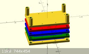
Instead of casting the electrodes. I've gotten this framing idea.
by stacking multiple frames I can extend the cell count as high as I want.
the electrodes and membrane will be layered between the blue inter section of the frame, sealed with caulk or something and screwed in place. Its hard
to see from that
angle but the larger holes in the 4 corners are liquid paths. the bottom right flows through the cell and out the upper left. by flipping the frame
around, the liquid will go
through the other channels. enabling me to keep the anode and cathode fluid separated. The smaller holes lining the border are for running long bolts
through to
compress and seal the array.
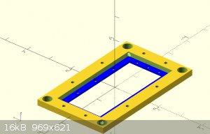
I looked up the compatibility chart for ABS filament. it says its good with NaOH, CL2, NaCl but not the acids.
Has anyone else tried this?
as well as fully customizable

"You can't do that" - challenge accepted
|
|
|
Rainwater
National Hazard
   
Posts: 925
Registered: 22-12-2021
Member Is Offline
Mood: Loving every second
|
|
Quote: Originally posted by mysteriusbhoice  | a feed source you can make it so that you have Na2SO4 as the working fluid which will form H2SO4 in the anode chamber until it reaches 35% before its
drained then the NaOH of the cathode liquid is intermittently widthrawn into a mixing chamber containing MgSO4 to react and form Mg(OH)2 and Na2SO4
again and thus Na ions are the catalyst here.
|
Looks like they make a pvc filament. Pvc will be compatible at < 50c. And < 25%by weight. Gonna wait for it to come in then print some frames.
Printing pvc producers some nasty gasses. Im going to have to setup my printer in the fume hood. If it fits.
Excuse me while i think out loud for a few moments.
(I really need to learn my equations properly)
Step1)
Na2SO4 + 2e- = 2Na(+) + SO4(2-)
Cathode -> 2(Na+) + H2O = 2NaOH + H2
Anode -> SO4(2-) + H2O = H2SO4 + (1/2) O2
Step 2)
2NaOH + MgSO4 = Mg(OH)2 + Na2SO4
MgSO4 (solubility 9.628×10^−4) so it will percipitate out of solution
[Edit] Mg(OH)2 not mgso4
Im only going to run low amps (<4) through these setups.
For the h2so4 i was thinking about piping the output directly to a boiling flask for continuous distillation at 120c. Then returning the h2o back into
the cycle.
But that brakes the rule about adding acid to water.
For the naoh solution it wouldnt be a problem. Cant remember at what temp provides a solution of 25% but i want to set up a continuous boiler
(stainless steel) there to concentrate the caustic solution to something usable. Then return the h2o to the cycle. Basicly im looking to build a
turnkey system which requires almost no action from me other than to collect my treasure every few days and top off some salt buckets.
Are there any good uses for mg(oh)2?
[Edited on 24-1-2022 by Rainwater]
"You can't do that" - challenge accepted
|
|
|
Rainwater
National Hazard
   
Posts: 925
Registered: 22-12-2021
Member Is Offline
Mood: Loving every second
|
|
Quote: Originally posted by mysteriusbhoice  | .... your best bet is a multi compartment membrane electrolysis cell divided into sections where you use planar electrodes and alternating cathode and
anode chambers ....
for membranes if you plan for best yield just use neutral PVC glue on cleaning cloth/fiberglass which was treated in 4 molar NaOH for 12 hours to make
it more permeable.
electrodes should be plates not meshes unless you want to conserve materials and anodes can be lead which is oxidized.
Overall membranes will allow more current draw then using ceramic pots as a single membrane 2 compartment cell ive run up to 10 amps at 8 volts now
imagine running like 4 membranes on 40 amps.
provided you can cool the liquids down this can indeed be doable. |
Nailed it. I'm getting a current draw like there is nothing there.
The current is the same with or without the membranes. My meter only has a resolution of 10mA.
Printed a few 2in x 2in (50mm x 50mm) test cell in pla.
Electroplated some printer paper painted with diy carbon ink. Copper went on smoth and easy
Whipped up a solution of lead nitrate. Plating was not as petty. I might invest in some 1/8 plates or a mill roller.
Lots of problems with it leaking. (Very small surface to seal) Hooked up 6 cells.
Connected peristaltic pumps from theelectrode chambers to a litter of distilled water(cathode) and a liter of saturated sodium bicarbonate solution
Powered by a timer. Left the timer off
Hours, volts, current
0 2.00 0.00
5 0.69 4.00
I started the pumps. Set them to pump 50 mL @ 10 minute intervals
After that my current would drop after the pump cycle was complete then quickly go back to 3 amps after a little work i was able to maintain 3.5-4
amps by pumping
10mL every 8 minutes.
"You can't do that" - challenge accepted
|
|
|
mysteriusbhoice
Hazard to Others
  
Posts: 477
Registered: 27-1-2016
Member Is Offline
Mood: Became chemistry catboy Vtuber Nyaa
|
|
so I take the project is a success with that post.
cant wait to see the yield results of sulfuric and how long the anodes would hold up.
They would in general easily hold up to these conditions
|
|
|
Rainwater
National Hazard
   
Posts: 925
Registered: 22-12-2021
Member Is Offline
Mood: Loving every second
|
|
So far, I was able to produce 73.48 grams of NaOH in 16 hours
Theoretical max yield is 89.95 grams for a start of 81% yield.
I know i lost some in transferring from the boiling dish, and some of the finished products contain h2o. (Was dried @ 200c for 2 hours.)
I believe my biggest inefficiency is the current drop when the pump is activated.
That's more of a calculation error than actually loss of efficiency.
Currently running 3 electrode pairs. which provides 5 anode/cathode area.
Edit: my math was wrong
Each has 50mm × 50mm exposed area (.25cm²)
.25 × 5 = 1.25cm² total area.
1.25cm² ÷ 4 amps = 0.3125 amps/cm²
Each plate is spaced 2mm from the membrane for a spacing of 4~5mm
My lead plating is degraded, and probley will not survive the next 24 hours.
The copper cathode is unaffected.
For a first try id say very successful.
I need to improve by lead anode.
I placed 100g of Pb(NO3)2 into a 1L beaker with some water
Added 4g 99% HNO3
Toped the beaker off to the 1 liter mark
Heated to 70c with stiring
then inserted a copper cathode and a lead anode and plated at 50mA for 2 hours. Rotated the cathode and plated for another 2 hours.
[Edited on 20-2-2022 by Rainwater]
"You can't do that" - challenge accepted
|
|
|
Fantasma4500
International Hazard
    
Posts: 1681
Registered: 12-12-2012
Location: Dysrope (aka europe)
Member Is Offline
Mood: dangerously practical
|
|
i read through some ancient book on electrochemistry chemical productions and in some cases a more "caked" up electrode would have better yield-
probably due to having microshapes that allows for some different formation, or simply higher surface area
my MMO doesnt respond well any longer, the front has gotten some white stuff going, but the backside seems almost brand new
so i think that one cant truly consider both sides of a flat electrode- or round electrode- to be active
i think you would want cathode on both sides to utilize anode the best
as for PbO2 anodes, i mixed up some maybe 6-7 years ago and never got to use it, i vaguely recall something more than just lead nitrate and HNO3 added
to it, maybe copper. i got this from patents- supposedly they didnt add it just for fun
the speed of electrodeposition will determine what kind of geometry that deposits on the electrode- the specifics of PbO2 i know nothing about
however, havent yet made any. i do recall a pre-coating of cobalt from a site called 110oxidizing or something, probably long gone. a small guide into
electrochemistry in creating electrodes, amperage, electrolytes etc, the cobalt was used prior PbO2 coating, to protect the material underneath, it
was a rod but i cant remember if substrate was titanium or graphite.
|
|
|
Rainwater
National Hazard
   
Posts: 925
Registered: 22-12-2021
Member Is Offline
Mood: Loving every second
|
|
Quote: Originally posted by Antiswat  | but the backside seems almost brand new
so i think that one cant truly consider both sides of a flat electrode- or round electrode- to be active
i think you would want cathode on both sides to utilize anode the best
|
The design i chosen has only 2 faces of electrodes wasted.
.... only has 1 face of 2 electrodes not being used.
$<"( hang on....... got it
Maximizes available surface area.
So each electrode of a given polarity is exposed on both sides to an electrode of opposite polarity, except the first and last electrode.
Dam i cant talk today.
The arrangement is as follows.
"C" = copper.
"P" = lead.
"|" = mysteriusbhoice's membrane
| Code: |
(Inlet plate) C | P | C | P | C | P (End plate)
|
| Quote: | | vaguely recall something more than just lead nitrate and HNO3 added to it, maybe copper. |
From my research. If your not using a lead anode to plate lead, it is best to add copper to the solution. A lot of papers say copper nitrate, or
carbonate. If i recall this is to maintain the conductive of the solution and to produce a distinct indication of when the lead has been depleted and
anode erosionis is accelerating. Because the copper will begin to plate out, you also have a visual indication of your end point.
Theres a dam good thread sticky'ed to the form about PbO anodes.
I think me doing the wrong math and having 300mA/cm² was the cause of errosion.
My anode was just paper with lead plated onto it.
I had few expectations of it lasting throughout the test.
My next try will be a fiberflass mesh (bug screen). With a copper conductive layer and 1mm think lead plating.
The holes in the mesh are 1mm spaced so im gonna plate until they close.
After i workout the leaking issues. I will post some more picks and my scad file.
Currently im using pla. It swells and absorbs water, then bust a seal. It reactive with KOH & NaOH and the completely wrong material for the job,
but very easy to print.
"You can't do that" - challenge accepted
|
|
|
mysteriusbhoice
Hazard to Others
  
Posts: 477
Registered: 27-1-2016
Member Is Offline
Mood: Became chemistry catboy Vtuber Nyaa
|
|
so you plate lead onto copper which makes a lead anode that then can oxidize into PbO2 when run anodically.
It can be viable to plate PbO2 directly onto your graphite or copper coated plastic by using a solution of 4 molar NaOH and PbO instead but you need
to make sure there is no contamination of nitrate ions if you plan to make PbO from lead nitrate.
Then optionally you can plate it anodically in a lead nitrate bath aswell afterwards and these PbO2 anodes should be good for producing even H2SO4
without much errosion if made properly.
|
|
|