| Pages:
1
..
61
62
63
64
65
..
68 |
NeonPulse
Hazard to Others
  
Posts: 417
Registered: 29-6-2013
Location: The other end of the internet.
Member Is Offline
Mood: Isolated from Reality! For Real this time....
|
|
too late to actually edit my post.... here's a quick video that was put together hastily depicting the linear charge:
https://www.youtube.com/watch?v=LoCr_I0mDcM&t=19s...
|
|
|
greenlight
National Hazard
   
Posts: 737
Registered: 3-11-2014
Member Is Offline
Mood: Energetic
|
|
44mm EFP
I have been constructing a new 44mm EFP charge over the past weeks to try and punch a hole through a target that has resisted every attempt with a
30mm design.

The specs are:
▪Diameter = 44 mm
▪Flyer thickness = 1.5 mm Cu
▪Casing = PVC
▪Charge Weight = 26 g PETN PE (16% inerts)
▪Standoff = 95cm
▪Target = 20mm steel
I usually sight the charge with a high powered laser pointer which helps a lot as it is quite difficult to get a direct hit just by eyeing it. Of
course the thing decides to shit itself today and makes sure it waits til I am at the test site to do it
The target plate is only the size of a dinner plate so it's a small area to hit but I sighted it by eye as best I could before inserting the cap and
initiating it.
Walked back to ground zero and wow, shock and awe, it hit high . .
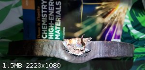
It is quite a decent hit though and quite a wide projectile due to the low head height of the charge. As can be seen by the photos, because it was so
close to the edge of the plate it penetrated for a bit and then lost kinetic energy to the side as it took the path of least resistance and slid off
over the top of the plate (that part was the top, plate was stuck in ground). You can also see stress fractures in the steel.
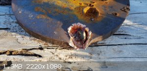 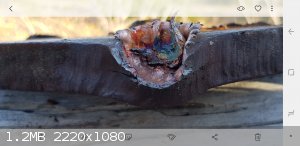
Also take into account the fact that it would have hit at a 10° angle instead of straight on, and the plate was just hammered into the ground and had
some movement.
Penetration from what I can record is about 13mm before it started moving laterally. Im sure it would have almost if not fully made it if the hit was
direct. Can always try some barrel tamping if not.
Guess I will have to step it up to a 50mm and have another crack at it, but first to find another decent laser pointer.
[Edited on 15-10-2018 by greenlight]
[Edited on 15-10-2018 by greenlight]
Be good, otherwise be good at it 
|
|
|
NeonPulse
Hazard to Others
  
Posts: 417
Registered: 29-6-2013
Location: The other end of the internet.
Member Is Offline
Mood: Isolated from Reality! For Real this time....
|
|
Nice job Greenlight. Still meaning to get around to trying these EFP setups. One day...
But here’s a very interesting video. Not so much unconventional but still shaped charges and some amazing footage: https://m.youtube.com/watch?v=dHfQYGGUS4U&autoplay=1
That penetrator on that door at the 4:00 minute mark displayed some great footage I’ve never seen before. Great job from these guys as usual.
[Edited on 20-10-2018 by NeonPulse]
|
|
|
greenlight
National Hazard
   
Posts: 737
Registered: 3-11-2014
Member Is Offline
Mood: Energetic
|
|
Thanks NP,
I can't believe you linked that! I was watching that exact video earlier today.
Yeah, that copper shaped charge was just beautiful to watch, the detcord and shocktube looked nice too and you get a pretty good view of the shockwave
in motion on the last one.
It still amazes me that such a lightweight liner weighing in the grams range hitting a barrel half full of water weighing multiple kgs has the ability
and force to throw the whole thing 9 or 10 inches off the ground.
P.S. Looking forward to seeing the properties of that perchlorate complex you made
[Edited on 21-10-2018 by greenlight]
Be good, otherwise be good at it 
|
|
|
Uriel
Harmless

Posts: 14
Registered: 28-1-2017
Member Is Offline
Mood: No Mood
|
|
Hi everyone.
Thank you for all your informations !
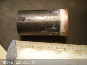
Here, my results after many fails. I have tried with plastic container, but it don’t work correctly.
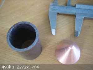
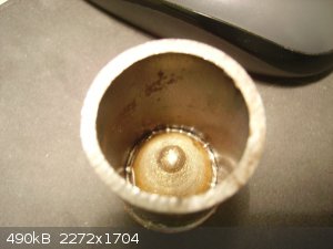
I read here that it need to be in steel pipe to work well. By chance, I’ve found a pipe of 2,4mm of wall thickness for 29mm inner diameter. It is
thin but it’s a test.
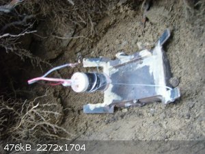
Here pipe is steel 50mm long by 29 inner diameter.
The copper cone was made by galvanoplastie at 90° (if my memories are good) and the thickness of the copper is about 1,4mm (estimated by mass/area).
I’ve put 38,3g of melting ETN but bubbles don’t make me reach a good density… So sad.
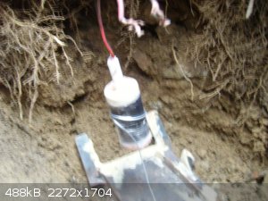
The detonator was at center, and made by 1,5g of ETN powder electrically ignited by 0,25g of TATP.
The penetration was 45mm in classic S235 steel. (Stack of 8mm plates).
The ratio penetration/diameter is 1,55… Quite bad against military performances, but I’m proud of me !!
Hope it can be be interesting for you !
(Next stage : RDX powder with EGDN, better density and VOD !)
(And as I've not 50mm diameter pipe, I will try with concrete, I'm sure it will contain a part of explosion)
Have a nice day guys.
     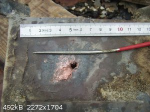 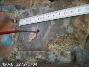
[Edited on 21-10-2018 by Uriel]
[Edited on 21-10-2018 by Uriel]
|
|
|
greenlight
National Hazard
   
Posts: 737
Registered: 3-11-2014
Member Is Offline
Mood: Energetic
|
|
Nice job, I never quite got those conical shaped charges right.
That amount of explosive seems quite high from memory of other peoples SC's but that liner is pretty thick at 1.4mm.
I have seen from previous tests that the gaps between the stacked up metal target plates also slows the jet down much faster than if it was a solid
target too by promoting breakup every time it has to re enter.
What was the standoff distance?
Be good, otherwise be good at it 
|
|
|
markx
National Hazard
   
Posts: 646
Registered: 7-8-2003
Location: Northern kingdom
Member Is Offline
Mood: Very Jolly
|
|
Purely for amusement purposes let's see how small one can go and still keep some focus from a shaped device.....
How about building one into a 5mm drinking straw....seems like a reasonable standard scale  ? ?
First we are going to need a setup for makeing the cone for the "Tiny" device
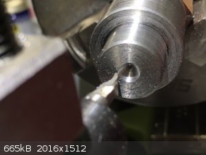 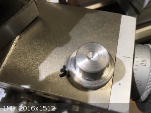
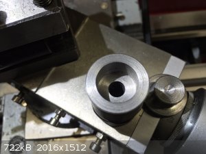 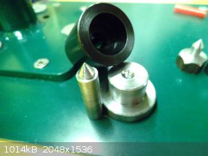
Lets see if we can form some copper with our contraption:
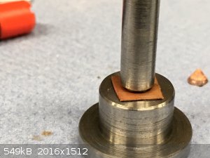 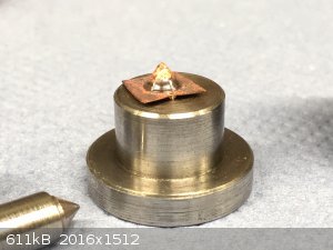
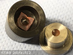 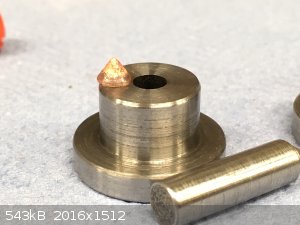
Pretty decent 5mm cone, aye (0,15mm thickness)....
We are going to need some reinforcement around that to force the energy down and out the business end:
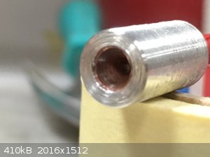 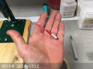
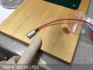 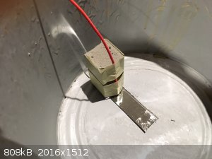
There we have it...the "Tiny" device literally buildt into a piece of plastic drinking straw with some Al reinforcement 
The result of the test:
2mm stainless 304 sheet, standoff 15mm, charge was 100mg SADS+ 250mg rdx
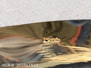 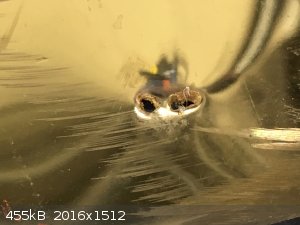 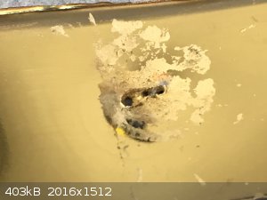
The jet split, but definitely we have a focused action going on....quite unbelievable that it could be this small and still have a profound effect.
The active part has a lesser dimesion than a .22 round...
Can we go even smaller? 
[Edited on 6-1-2019 by markx]
Exact science is a figment of imagination.......
|
|
|
nitro-genes
International Hazard
    
Posts: 1048
Registered: 5-4-2005
Member Is Offline
|
|
Nice, I bet homogeneously loading and aligning these charges is challenging. For loading, I think it might help if the cone is supported by the
positive mold piece to prevent the liner from deforming. If the positive mold would also have a small overhang to support the casing, the liner
alignment also wouldn't change during pressing. Another idea might be to preload the explosive in the casing, and press in the liner while it is
supported by the positive mold. The liner itself might turn out to be even more precise if during pressing, one of the mold pieces would be spinning
(using lubrication).
To achieve homogeneous loading density, a PBX would also seem better as powdered RDX, 3-5% inerts or active binder would probably suffice, though
performance may drop due to critical diameter. IIRC, particle size also affects critical diameter, so making the RDX crystals as small as possible
would further help. Finely powdered PETN or so would seem even better for these diameters.
[Edited on 7-1-2019 by nitro-genes]
|
|
|
markx
National Hazard
   
Posts: 646
Registered: 7-8-2003
Location: Northern kingdom
Member Is Offline
Mood: Very Jolly
|
|
Quote: Originally posted by nitro-genes  | Nice, I bet homogeneously loading and aligning these charges is challenging. For loading, I think it might help if the cone is supported by the
positive mold piece to prevent the liner from deforming. If the positive mold would also have a small overhang to support the casing, the liner
alignment also wouldn't change during pressing. Another idea might be to preload the explosive in the casing, and press in the liner while it is
supported by the positive mold. The liner itself might turn out to be even more precise if during pressing, one of the mold pieces would be spinning
(using lubrication).
To achieve homogeneous loading density, a PBX would also seem better as powdered RDX, 3-5% inerts or active binder would probably suffice, though
performance may drop due to critical diameter. IIRC, particle size also affects critical diameter, so making the RDX crystals as small as possible
would further help. Finely powdered PETN or so would seem even better for these diameters.
[Edited on 7-1-2019 by nitro-genes] |
All true and good suggestions  ! But yes, the critical diameter is already on the
verge as is, even for pure substance. I used ultrafine particle size product from an ancient experiment that I conducted with straight nitric acid and
hexamine. It is actually the purest sample that I have according to melting point measurements and the finest, thus also the easiest to kick off in
such small diameter. Even with this one I get problems of partial or no detonation sometimes. The Bachmann variety is hopeless in such application, at
least if not specially recristallised to obtain very fine particles. ! But yes, the critical diameter is already on the
verge as is, even for pure substance. I used ultrafine particle size product from an ancient experiment that I conducted with straight nitric acid and
hexamine. It is actually the purest sample that I have according to melting point measurements and the finest, thus also the easiest to kick off in
such small diameter. Even with this one I get problems of partial or no detonation sometimes. The Bachmann variety is hopeless in such application, at
least if not specially recristallised to obtain very fine particles.
I actually intended to use penthrite, it is vastly superior for such small diameters, but I did not have time for a synth, hence the old rdx stock
came out of hibernation. further downscaling shall be reserved only for petn based systems.
The loading is conducted as you suggested: over a matching support piece to keep the cone aligned and straight. You can actually glimpse at it in the
"green picture" the hefty nail like object with hexagonal base on the right side is the loading support.
The liner should actually be finished in lathe after being formed to ensure even wall thickness. It does stretch out unevenly and has bad focus due to
that. Also a final annealing run should be performed on it before loading to equalize the stress.
Exact science is a figment of imagination.......
|
|
|
Laboratory of Liptakov
International Hazard
    
Posts: 1387
Registered: 2-9-2014
Location: Technion Haifa
Member Is Offline
Mood: old jew
|
|
copper cone
Good device.... I recommend use one between annealing operation. For better
thickness on peak of cone.... I recommend use one between annealing operation. For better
thickness on peak of cone....
Development of primarily - secondary substances CHP (2015) Lithex (2022) Brightelite (2023) Nitrocelite and KC primer (2024)
|
|
|
markx
National Hazard
   
Posts: 646
Registered: 7-8-2003
Location: Northern kingdom
Member Is Offline
Mood: Very Jolly
|
|
One annealing cycle in the process of forming is not enough. One has to use at least four cycles and different geometry forming tools to get reliable
results. After every forming operation the workpiece is annealed or it will stretch unevenly and break during next operation.
The pictured forming tool is the last one for final shaping of the tip and the geometry of the cone. The process starts with a round forming tool to
dish out the copper foil and then proceeds with one that slightly resembles the cone geometry, but with a rounded dull tip. Then the final former is
used to give the workpiece the correct shape.
Exact science is a figment of imagination.......
|
|
|
Laboratory of Liptakov
International Hazard
    
Posts: 1387
Registered: 2-9-2014
Location: Technion Haifa
Member Is Offline
Mood: old jew
|
|
copper cone
Thanks for details explanation, Marks. Useful information for anyone.....
Development of primarily - secondary substances CHP (2015) Lithex (2022) Brightelite (2023) Nitrocelite and KC primer (2024)
|
|
|
markx
National Hazard
   
Posts: 646
Registered: 7-8-2003
Location: Northern kingdom
Member Is Offline
Mood: Very Jolly
|
|
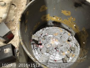
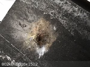
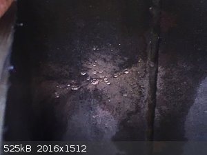
I examined the paint bucket that I conducted the test in more closely and the crazy part is that the jet seems to have extended to more than 55mm from
zero standoff level. The device had 15mm standoff from target and then 40mm of spacing between the target and container bottom.
That is the container bottom below the target:
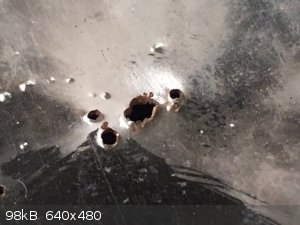 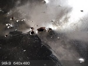
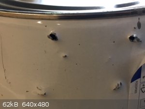
The container itself has been turned to a sieve from the shrapnel of the aluminium casing (serves as an illustration to the importance of containing
these metal pieces at all cost and choosing a safe location for any live testing to be conducted):
The situation at the container bottom is highly curious though....55mm is about 11 CD from zero standoff. I think some of the holes may have been
generated by material flung out from the target, but the center one is covered in clearly a copper residue and suspiciously the pattern coincides with
the triple splitting of the jet that can be seen at the target. Could it really be that the jet extended this far away from the actual impact point
and still remained focused enough to go through the container bottom and into the concrete below?
Exact science is a figment of imagination.......
|
|
|
nitro-genes
International Hazard
    
Posts: 1048
Registered: 5-4-2005
Member Is Offline
|
|
IIRC, the splitting of the jet could be due to several factors: one is stresses in the liner. Spun formed liners can exhibit this behavior as well,
which had something to do with the stresses in the liner material by the spinning operation introducing axial rotation during liner collapse. Also
noticed that re-annealed the liner after spinning would mostly solve this. Can't imagine the pressing operation producing the same stresses in the
liner as spinning, so maybe in this case the it may also be an effect of an overdriven liner. Was the 0.15 mm copper thickness of the liner measured
before or after pressing? Also noticed you used quite some sub calibration. The 0.15 mm after pressing may be more like 0.12 mm after and with another
3 mm's of subcalibration, the liner would be more like ~1% of CD instead of the optimal 2% for a 60 deg copper cone. Maybe slower slug fragments could
also explain the penetration of the bottom container?
Think I mentioned this before: Liner precision, charge alignment and loading density homogenity are the absolute key requirements for long
penetrations. I think both pressed and spun liners may produce deviations in the order of 50-200 um, while IIRC, only several micrometers are allowed
to produce >5 CD penetrating charges. Note that this kind of precision is even out of reach for most lathes! Or you would need to build one like
this! (Still on my loooong list of plans  ) )
https://www.youtube.com/watch?v=sFrVdoOhu1Q
Even then, any after machining on a such lathe would probably prove very challenging in practice anyway. Curious how professional liners are produced
to reach this kind of precision exactly.
Regarding the explosive, PETN/NG as Axt also used would probably be one of the best for these very small liners IMHO. 
[Edited on 10-1-2019 by nitro-genes]
|
|
|
Laboratory of Liptakov
International Hazard
    
Posts: 1387
Registered: 2-9-2014
Location: Technion Haifa
Member Is Offline
Mood: old jew
|
|
copper cone
Also it can be too much highly energy on 0,15 mm of copper cone. Else words, copper cone is too thin for high energy from explosive. Therefore has
behavior as flame from rocket engine. Because any unprecision of copper cone thickness is cause for fragmentation at so highly energy. Require it
thickness 0,3 mm of cone with a same EM. Or 0,15 mm, but with weaker (slower) EM. After it you will (maybe) only one hole in plate....
Development of primarily - secondary substances CHP (2015) Lithex (2022) Brightelite (2023) Nitrocelite and KC primer (2024)
|
|
|
markx
National Hazard
   
Posts: 646
Registered: 7-8-2003
Location: Northern kingdom
Member Is Offline
Mood: Very Jolly
|
|
Quote: Originally posted by nitro-genes  | IIRC, the splitting of the jet could be due to several factors: one is stresses in the liner. Spun formed liners can exhibit this behavior as well,
which had something to do with the stresses in the liner material by the spinning operation introducing axial rotation during liner collapse. Also
noticed that re-annealed the liner after spinning would mostly solve this. Can't imagine the pressing operation producing the same stresses in the
liner as spinning, so maybe in this case the it may also be an effect of an overdriven liner. Was the 0.15 mm copper thickness of the liner measured
before or after pressing? Also noticed you used quite some sub calibration. The 0.15 mm after pressing may be more like 0.12 mm after and with another
3 mm's of subcalibration, the liner would be more like ~1% of CD instead of the optimal 2% for a 60 deg copper cone. Maybe slower slug fragments could
also explain the penetration of the bottom container? PETN/NG as Axt also used would probably be one of the best for these very small liners IMHO.

[Edited on 10-1-2019 by nitro-genes] |
Yes, I did downengineer the liner thickness in fear of not having enough impulse to getting good focus in such a small device. And as life has shown
things do not down or upscale in a linear manner....at least most of the times you expect them to do so, they won't 
The liner thickness was measured after forming with a digital caliper on the outer verge, so not to cutting edge of precision standards, but gives a
rough outline of the picture. The jet splitting is due to liner inconcistency as you mentioned. I've also seen similar pattern in pressed soft steel
liners. Either because of uneven thickness or because of stresses that develop during forming operation. But very likely both factors are at play
here, as the liner does not stretch totally evenly during forming and it was not annealed after last forming operation. Copper develops an incredible
amount of internal stress due to deformation and this will most definately affect the jet formation. In ideal conditions the liner should be cut even
on both surfaces after being pressed and then annealed before application to relieve the lattice stress. At the very least it should be
annealed....machining this tiny detail in a lathe is challenging at worst 
I had little hope for success, so I bothered not to do either. Not to mention I had to be disappointed again!
So I set forth to go even smaller this time (3,5mm liner):
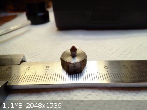 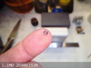
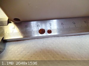 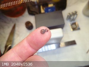
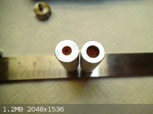 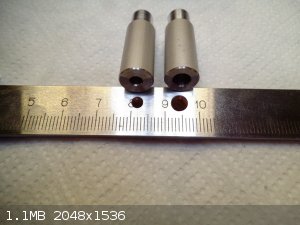
And I machined a full set of tools for preparing the little contraptions:
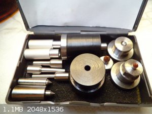 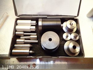
Exact science is a figment of imagination.......
|
|
|
Laboratory of Liptakov
International Hazard
    
Posts: 1387
Registered: 2-9-2014
Location: Technion Haifa
Member Is Offline
Mood: old jew
|
|
In such small objects, the proportional - ratio law is manifested. For example, a critical average for EM. Which applies also for copper and his
behavior. Too less molecules = else behaviours.
Development of primarily - secondary substances CHP (2015) Lithex (2022) Brightelite (2023) Nitrocelite and KC primer (2024)
|
|
|
markx
National Hazard
   
Posts: 646
Registered: 7-8-2003
Location: Northern kingdom
Member Is Offline
Mood: Very Jolly
|
|
Well, its time to test out the 3,5mm microcone device....
The annealed 3,5mm Cu cone (0,16mm wall thickness) is inserted on the support jig and 170mg of penthrite is pressed into the casing in two stages. The
first 100mg stage is pressed quite dense and the second one (70mg) is left in a less compacted state to ease initiation. 100mg of SADS is compacted on
top of penthrite as the last operation:
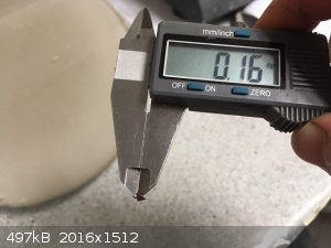 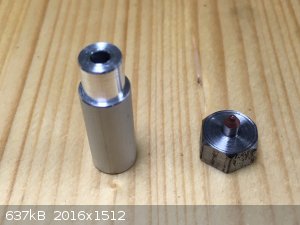 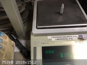
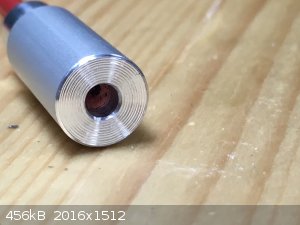
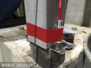
The microcone device is completed. It has 3mm offset (appr. 1CD) "built in" because of the cone support jig:
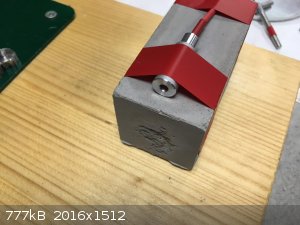
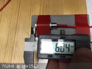
The device is fixed to a concrete stand with tape and another 6mm worth of offset is added:
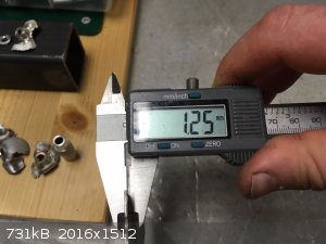
1,25mm 304 stainless sheet is chosen as the target and the device is configured as following for the test. I must note that this is the same sheet of
stainless used in the previous 5mm "Tiny" device test. I assumed it to be 2mm stock, but upon measuring it comes out just about 1,25mm thickness :
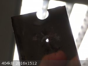
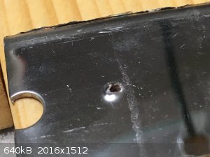
After the test we have complete and utter success. The target is cleanly penetrated with a nicely focused single jet and there is no splitting. I also
managed to retrieve the bottom and top parts of the aluminium casing:
  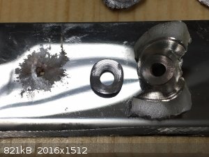
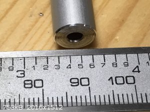
The jet channel and the cone that formed it side by side. The cone in the picture has a broken tip (careless forming ruptured the tip of the cone),
but it still serves as a scale indicator:
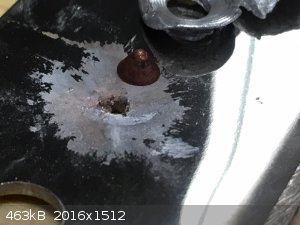 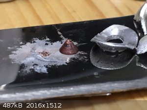
Quite amazing really....even the 5mm device seemed impossibly downscaled for a successful jet formation and here we have a 3,5mm device that displays
full functionality. Could we go even smaller.......say a 2mm device? 
Exact science is a figment of imagination.......
|
|
|
Laboratory of Liptakov
International Hazard
    
Posts: 1387
Registered: 2-9-2014
Location: Technion Haifa
Member Is Offline
Mood: old jew
|
|
copper cone
Good successful. It seems, that spherical - bulb peak of cone is better. And else angle I see, estimate. Also small main charge. Only 170 mg.
Stainless plate is same, 1,25 mm. Or 5 mm steel. A lot entertainment with minimal EM..........
Development of primarily - secondary substances CHP (2015) Lithex (2022) Brightelite (2023) Nitrocelite and KC primer (2024)
|
|
|
nitro-genes
International Hazard
    
Posts: 1048
Registered: 5-4-2005
Member Is Offline
|
|
While going through the miniatures of the photos you posted I was like "Why would he post a photo of an empty caliper?" lol. Any smaller and you would
need to go "Willard Wigan" style probably!  Really love the toolset you made for
the miniature liners btw! Really love the toolset you made for
the miniature liners btw!
The relatively large penetration hole is probably mostly the result of the hemispherical part of the liner (This part produces a slower jet than the
conical part of the liner). Having a slight trumpet shape and/or sharp cone and >2 CD headheight/waveshaper above the liner, the charge produces
only a very narrow jet channel. Made a 17mm charge this way once, it blew a hole through 5 cm of steel, but the only thing visible was the smallest
pinhole trough the steel for which I doubt even a needle could have fit through. 
A possible idea for visualization...aluminium is somehwat lighter metal, it may provide a bete visualization of the jet channel than steel. Also, what
if you would stack very thin steel (or aluminium) plates head-on (so || instead of =), support them by a strong frame to prevent sideway displacement
too much and then fire the charge? Could you peel the steel plates like an onion or would the plastic flow weld all plates together? Probably the
latter, still worth a try maybe. Could even make a casting of the jet channel perhaps.  Easiest for making as positive cast of the jet channel seems firing the charge into a piece of steel tube filled with a low melting lead
solder (IIRC, they come down to <100 deg. C.), casting in epoxy or something and melting away the solder again, how cool is that! Easiest for making as positive cast of the jet channel seems firing the charge into a piece of steel tube filled with a low melting lead
solder (IIRC, they come down to <100 deg. C.), casting in epoxy or something and melting away the solder again, how cool is that! 
[Edited on 12-1-2019 by nitro-genes]
|
|
|
markx
National Hazard
   
Posts: 646
Registered: 7-8-2003
Location: Northern kingdom
Member Is Offline
Mood: Very Jolly
|
|
Quote: Originally posted by nitro-genes  |
The relatively large penetration hole is probably mostly the result of the hemispherical part of the liner (This part produces a slower jet than the
conical part of the liner). Having a slight trumpet shape and/or sharp cone and >2 CD headheight/waveshaper above the liner, the charge produces
only a very narrow jet channel. Made a 17mm charge this way once, it blew a hole through 5 cm of steel, but the only thing visible was the smallest
pinhole trough the steel for which I doubt even a needle could have fit through. 
[Edited on 12-1-2019 by nitro-genes] |
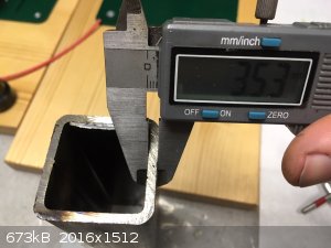
Hmmm...a needle hole like this one? 
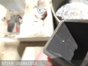
Made by a 5mm liner going through 3,5mm mild steel rectangular tube. I only packed 150mg penta charge into this one and it still went through.
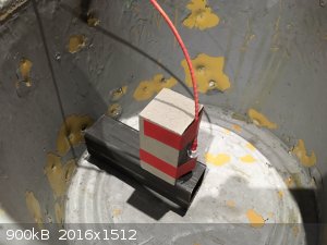
  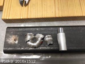
Bottom side of the tube got a beating too:
[Edited on 12-1-2019 by markx]
Exact science is a figment of imagination.......
|
|
|
Fulmen
International Hazard
    
Posts: 1716
Registered: 24-9-2005
Member Is Offline
Mood: Bored
|
|
Don't get me wrong, that's good performance. I've drawn some liners myself and it's not as simple as one would think, I've seen my share of split jets
and crazy splattering. Just getting a single clean jet is good work. But compared to the professional devices it's pretty poor. I mean, where's the
multi-caliber penetration with long standoffs? I haven't seen it so far with anything I've put together either.
I've wondered if it's worth the effort to swage the entire cone, i.e. a close-fitting die/mandrel and enough force to press the entire cone plastic.
I'll have to borrow a bigger press for anything in my size-range (15-30mm caliber), and I'm low on good tool steel.
We're not banging rocks together here. We know how to put a man back together.
|
|
|
markx
National Hazard
   
Posts: 646
Registered: 7-8-2003
Location: Northern kingdom
Member Is Offline
Mood: Very Jolly
|
|
Quote: Originally posted by Fulmen  | Don't get me wrong, that's good performance. I've drawn some liners myself and it's not as simple as one would think, I've seen my share of split jets
and crazy splattering. Just getting a single clean jet is good work. But compared to the professional devices it's pretty poor. I mean, where's the
multi-caliber penetration with long standoffs? I haven't seen it so far with anything I've put together either.
I've wondered if it's worth the effort to swage the entire cone, i.e. a close-fitting die/mandrel and enough force to press the entire cone plastic.
I'll have to borrow a bigger press for anything in my size-range (15-30mm caliber), and I'm low on good tool steel. |
I guess our efforts do not amount to such performance as displayed by the cutting edge of the field....still good fun though 
How about machining a cone from solid stock instead of press forming/swaging? Machining should create less inconcistancy in the liner than drawing it
from a sheet metal form...
Exact science is a figment of imagination.......
|
|
|
Fulmen
International Hazard
    
Posts: 1716
Registered: 24-9-2005
Member Is Offline
Mood: Bored
|
|
True, but it's not as simple as it sounds. The trick is holding the part, I guess it could be glued to a mandrel. And copper is a PITA to machine. And
aluminum just feels wrong when copper is so much better. What's the verdict on brass or bronze?
We're not banging rocks together here. We know how to put a man back together.
|
|
|
markx
National Hazard
   
Posts: 646
Registered: 7-8-2003
Location: Northern kingdom
Member Is Offline
Mood: Very Jolly
|
|
Quote: Originally posted by Fulmen  | | True, but it's not as simple as it sounds. The trick is holding the part, I guess it could be glued to a mandrel. And copper is a PITA to machine. And
aluminum just feels wrong when copper is so much better. What's the verdict on brass or bronze? |
I know.....I have been dealing with the issue  The machining part is ok, one
just needs very sharp small steel cutting tools and lots of good cutting oil. Forget about carbide inserts for copper. They bind and gall and ruin the
surface. With a small steel cutter and good oil you can get a mirror finish on pure copper. LOCTITE LB 8031 is a rather good all around cutting and
threading oil. I've found it to work on most metals and alloys. The machining part is ok, one
just needs very sharp small steel cutting tools and lots of good cutting oil. Forget about carbide inserts for copper. They bind and gall and ruin the
surface. With a small steel cutter and good oil you can get a mirror finish on pure copper. LOCTITE LB 8031 is a rather good all around cutting and
threading oil. I've found it to work on most metals and alloys.
If one was to start from a round stock then the stock itself can act as the holder. One finishes the inner surface and then gradually goes about the
outer one until the cone tip releases the part. It is a tremendous amount of work though and very likely one just breaks in the last 15%, starts
increasing cuts, the part deforms, binds up on the cutter and all goes to hell  But it can be done....
Do not know though if it has much of an advantage over a formed liner as far as multicaliber penetration depths go.
With already formed liner the only way is to glue them to mandrels and machine over them. LOCTITE 4062 is a good choice for that purpose. It has
extreme wetting capability, instantaneous curing between metal surfaces, it can be released by moderate heat and the residue can be removed by
toluene, butyl acetate or xylene based solvents. The cured glue gels up and releases from surfaces very cleanly.
In fact I already machined one mandrel to finish the small liners in lathe after forming, but I wanted to test out if it works at all in such
diameters before proceeding to more complicated finishing operations. Seems that there is potential....
[Edited on 13-1-2019 by markx]
Exact science is a figment of imagination.......
|
|
|
| Pages:
1
..
61
62
63
64
65
..
68 |