| Pages:
1
..
56
57
58
59
60
..
68 |
magicchemist
Harmless

Posts: 6
Registered: 24-1-2016
Member Is Offline
Mood: No Mood
|
|
I roll until all gasoline is evaporated (3-4 hours).
|
|
|
nitro-genes
International Hazard
    
Posts: 1048
Registered: 5-4-2005
Member Is Offline
|
|
@greenlight, nice still shot there, btw... you wouldn't happen to have an e-version of the book by any chance? 
|
|
|
greenlight
National Hazard
   
Posts: 763
Registered: 3-11-2014
Member Is Offline
Mood: Energetic
|
|
Unfortunately, I only have the book as an actual hardcover for the bookshelf
|
|
|
Hennig Brand
International Hazard
    
Posts: 1284
Registered: 7-6-2009
Member Is Offline
Mood: No Mood
|
|
Quote: Originally posted by nitro-genes  | Henning, you remember what page that was about the volume displacements in FoSC by any chance? Considering the differences in mass/velocity relation
between an EFP and CSC would seem counter intuitive to have the same volume displacement indeed.
Also target effects are likely different, the jet of a CSC moves so fast, the collision behaves nearly completely fluid, similar to a stream of water
hitting a mudbank as I understand it. Forces are exerted to all sides from the colliding jet tip, like a fluid would, pushing the target material out
of the way and even creates a "backward" stream of liner/target material that is expelled from the formed canal. So not all energy is transferred to
the target and seems different from an EFP impact indeed. Wondered if you would weigh the target before and after firing, how much of the target
material would be gone, though, the liner will also deposit material of course, making this hard to determine.
[Edited on 23-1-2016 by nitro-genes] |
Had to do a little back tracking in this thread. Found it!
http://www.sciencemadness.org/talk/viewthread.php?tid=10575&...
"A risk-free world is a very dull world, one from which we are apt to learn little of consequence." -Geerat Vermeij
|
|
|
Laboratory of Liptakov
International Hazard
    
Posts: 1447
Registered: 2-9-2014
Location: Tel Aviv University
Member Is Offline
Mood: old jew
|
|
cast iron
Greenlight, congratulations. But:
Cast iron is much less firm. Especially on impact is low. If the tanks were made of cast iron, a big steel mallet would be enough to break apart. It
are not same conditions for attempts. At drilling cast iron, arises grain. At drilling steel, arises long metal chips. Cast iron has high content
carbon. About 4%. Steel only about 1%. From cast iron grain, you will be dirty the fingers from carbon. As from pencil. You can try and see.
Therefore is hole crushed as ice. So as so, nice a piece of work. And beauty photos.
Dr. Liptakov
|
|
|
nux vomica
Hazard to Others
  
Posts: 267
Registered: 18-7-2013
Member Is Offline
Mood: No Mood
|
|
Quote: Originally posted by Laboratory of Liptakov  | Greenlight, congratulations. But:
Cast iron is much less firm. Especially on impact is low. If the tanks were made of cast iron, a big steel mallet would be enough to break apart. It
are not same conditions for attempts. At drilling cast iron, arises grain. At drilling steel, arises long metal chips. Cast iron has high content
carbon. About 4%. Steel only about 1%. From cast iron grain, you will be dirty the fingers from carbon. As from pencil. You can try and see.
Therefore is hole crushed as ice. So as so, nice a piece of work. And beauty photos.
Dr. Liptakov |
Your right there liptakov here is a photo of the differance
Between steel and cast iron when its drilled
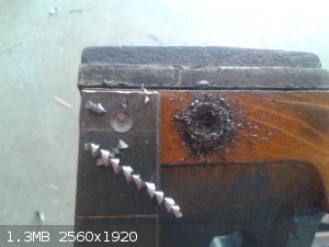
Cheers nux.
|
|
|
Laboratory of Liptakov
International Hazard
    
Posts: 1447
Registered: 2-9-2014
Location: Tel Aviv University
Member Is Offline
Mood: old jew
|
|
cast iron
Well, we everybody thanks for this photo. Clearly different material. Doc....:-)
|
|
|
greenlight
National Hazard
   
Posts: 763
Registered: 3-11-2014
Member Is Offline
Mood: Energetic
|
|
Thanks guys, celebrated too early
New target next time i think, I have a 19mm plate that has been hit 3 times with a 30mm EFP and I haven't been able to get a penetration yet (nothing
worth posting).
I think a 40mm EFP might be in order...
|
|
|
nitro-genes
International Hazard
    
Posts: 1048
Registered: 5-4-2005
Member Is Offline
|
|
Thanks for looking up that chart of volume displacements for different charge types Henning. Curious how they measured 300 individual hole volumes for
the fragmenting charge. Considering the difference in surface area between the flat cone SC and the fragmenting charge, it would seem the fragmenting
charge would transfer considerably more energy to the witness plate, would seem that above a certain headheight the energy transfer to the liner in
the flat bottom CSC is not transfered miraculously all to the liner, so my guess would also be that this has to be taken with a grain of salt indeed.

[Edited on 2-2-2016 by nitro-genes]
|
|
|
Laboratory of Liptakov
International Hazard
    
Posts: 1447
Registered: 2-9-2014
Location: Tel Aviv University
Member Is Offline
Mood: old jew
|
|
liner
40mm diameter of liner? Huuh... heavy caliber. How will be thick copper
concave? Thanks, Im curious. LL ... heavy caliber. How will be thick copper
concave? Thanks, Im curious. LL ...
|
|
|
greenlight
National Hazard
   
Posts: 763
Registered: 3-11-2014
Member Is Offline
Mood: Energetic
|
|
Yeah, I think I need to step it up after hitting this 19mm plate with three 30mm EFP's of varying charge weights and only getting half to 2/3 through
the target and in the case of the larger charge, the start of liner breakup.
I will be using 1mm thick copper and using the dapping tool I have and the 40mm side, I think the concave (dish) will be around 6 mm deep. I am
curious to see result as well, will be uploaded soon as a new batch of PE is made.
|
|
|
Laboratory of Liptakov
International Hazard
    
Posts: 1447
Registered: 2-9-2014
Location: Tel Aviv University
Member Is Offline
Mood: old jew
|
|
ratio EFP
Thanks green, 1 mm copper? Hmm... It is maybe thin plate. Of course, working will be it always. But transfer energy on target can be weakly. Maybe
using soldering 1+1 mm Cu. I somewhere spend data for counting EFP assemble. Therefore I only estimated. So as so, I am curious. Height of cylinder
explosive is same as diameter, it is usually basic. Thus 0,8 - 1,2 from diameter. But counting of ratio for thick of liner and his depth no and no
find. LL...
|
|
|
greenlight
National Hazard
   
Posts: 763
Registered: 3-11-2014
Member Is Offline
Mood: Energetic
|
|
1mm is the only copper plate I have at the moment. If it is not sufficient, I will use thicker.
Are u suggesting to use 2mm as the copper liner thickness?
I do try and keep the head height of the explosive the same as the diameter of the liner but with the last two batches of plastic explosive, they have
only been 1/2 to 2/3 the diameter of the liner due to the higher densities from extended rolling to improve performance.
|
|
|
Hennig Brand
International Hazard
    
Posts: 1284
Registered: 7-6-2009
Member Is Offline
Mood: No Mood
|
|
Quote: Originally posted by nitro-genes  | Thanks for looking up that chart of volume displacements for different charge types Henning. Curious how they measured 300 individual hole volumes for
the fragmenting charge. Considering the difference in surface area between the flat cone SC and the fragmenting charge, it would seem the fragmenting
charge would transfer considerably more energy to the witness plate, would seem that above a certain headheight the energy transfer to the liner in
the flat bottom CSC is not transfered miraculously all to the liner, so my guess would also be that this has to be taken with a grain of salt indeed.

[Edited on 2-2-2016 by nitro-genes] |
No problem, I find it interesting too. Those values in the chart are estimates, just how much I don't know. I have made quite a few small shaped
charges, but I still find my understanding pretty basic and probably inaccurate in many ways.
This is just the first reference I found in minutes.
From, "Shaped Charges Pierce Toughest Targets":
"A shaped charge, by design, focuses all of its energy on a single line, making it very accurate and controllable. When size is added to that
accuracy, the effect can be dramatic"
This says two things which we already know:
1. Shaped charges focus the explosive energy into the liner, not omnidirectionally like in most fragmentation type charges.
2. Given a certain accuracy large shaped charges will perform much better (it is much harder to make efficient the tiny shaped charges that we make!).
Being off by 1 mm in a shaped charge with a 25mm dimension is much worse than being off by 1 mm in a shaped charge with 500 mm for the same dimension.
It may say things about other improvements in efficiency/effect as well with larger charges.
In a simple energy conversion situation (ex. such as when electrical energy is made from some sort of mechanical energy, then transferred, then
stored, then transferred, then converted to mechanical energy again, etc, etc) all of these processes have a certain efficiency. The overall
efficiency for the process is the product of all those efficiencies. It is easy to see with even small inaccuracies that the overall efficiency could
get very low. Lets say we have 5 variables/processes and they are all 90% efficient, 0.90 * 0.90 * 0.90 * 0.90 * 0.90 = 0.59 or only 59% efficiency
overall. I assume it would be the same type of situation with shaped charges.
Attachment: Shaped Charges Pierce Toughest Targets.pdf (334kB)
This file has been downloaded 833 times
Thought I might make one or two more comments here.
Quote: Originally posted by nitro-genes  | Henning, you remember what page that was about the volume displacements in FoSC by any chance? Considering the differences in mass/velocity relation
between an EFP and CSC would seem counter intuitive to have the same volume displacement indeed.
Also target effects are likely different, the jet of a CSC moves so fast, the collision behaves nearly completely fluid, similar to a stream of water
hitting a mudbank as I understand it. Forces are exerted to all sides from the colliding jet tip, like a fluid would, pushing the target material out
of the way and even creates a "backward" stream of liner/target material that is expelled from the formed canal. So not all energy is transferred to
the target and seems different from an EFP impact indeed. Wondered if you would weigh the target before and after firing, how much of the target
material would be gone, though, the liner will also deposit material of course, making this hard to determine.
[Edited on 23-1-2016 by nitro-genes] |
I believe most of those losses, especially in full sized devices, would be fairly minor in comparison to what is transferred to the target. The author
did use the term approximation, or approximate, at least once or twice I believe also. I also think that once above the pressure needed to cause
plastic deformation in the target that the amount of energy needed to remove material, or most often push material out of the way, is likely fairly
consistent even as pressure increases well beyond this lower limit.
[Edited on 3-2-2016 by Hennig Brand]
"A risk-free world is a very dull world, one from which we are apt to learn little of consequence." -Geerat Vermeij
|
|
|
Laboratory of Liptakov
International Hazard
    
Posts: 1447
Registered: 2-9-2014
Location: Tel Aviv University
Member Is Offline
Mood: old jew
|
|
recounting EFP
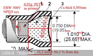
Well, understand. 1/2 from dia is low height of cylinder. Here is original assemble the scheme from factory. Original scheme is black, my write is
red. Thus: we have 19,05 mm diameter, for Copper thickness 0,505 mm. But We need counting thick liner from flat. No from line. Thus, Pí r2. = 19,05
is flat 2,85 cm2. But Dia 4 cm is flat 12,56 cm2. Next: 0,505 mm is good for 2,85 cm2. And for 12,56 cm2 is good thick 2,22 mm copper plate. ( 0,505:
2,85 = 0,177 x 12,56 = 2,223) Thus index is thick 0,177 mm on one and every cm2 of flat large. 4cm diameter = flat (radius x radius x3,14) = 12,56 x
index 0,177 = 2,23 thick of copper. And next important is of course height of cylinder. In scheme 86% from diameter. However is there still PETN,
which creates 15 % from all amount of charge. But also height of cylinder, partially. After recounting it is almost precise height = diameter. From
this reasons, I recommended thick of liner minimal 2 mm, for dia. 4cm. Because professional engineers (from factory on EFP) know what they do it.
Dr. Liptakov
|
|
|
greenlight
National Hazard
   
Posts: 763
Registered: 3-11-2014
Member Is Offline
Mood: Energetic
|
|
Thanks LL...
The head height of explosive is usually closer to 2/3 diameter of liner. It is hard because density of my PE is about 1.4-1.44 g/cm3 and the optimum
charge weight I have found for 0.91mm liner is about 17-18 grams. This amount only comes up about 2/3 high when pressed into the charge casing. If
more explosive is used like last time with the 19mm plate 20 grams was used and resulted in more breakup of the liner and not a good hit on the
target.
I think you are right about the thicker liner and I will increase the thickness for the 40mm EFP.
Maybe even 30mm calibre EFP could benefit with a better effect on the 19mm plate if liner is thicker and charge weight increased slightly.
[Edited on 4-2-2016 by greenlight]
|
|
|
Microtek
National Hazard
   
Posts: 920
Registered: 23-9-2002
Member Is Offline
Mood: No Mood
|
|
If the liner breaks up with more explosive, then I think that is an indication that a thicker liner should be used (at least if you have ruled other
factors, such as imprecisions in the symmetry, out).
|
|
|
greenlight
National Hazard
   
Posts: 763
Registered: 3-11-2014
Member Is Offline
Mood: Energetic
|
|
The liners are made with a dapping block and rounded by being rotated on a bench grinder until the exact diameter is reached so they are quite
symmetrical.
I have hit the 19 mm plate with 3 EFP's so far of 30mm diameter and liner thickness 0.91mm and the maximum penetration I have achieved is 12.5mm.
Thicker liner it is then, I will try a 1.2mm and 1.5mm thick liner before moving on to the 40mm size charge.
|
|
|
Hennig Brand
International Hazard
    
Posts: 1284
Registered: 7-6-2009
Member Is Offline
Mood: No Mood
|
|
Getting the right liner thickness was definitely my biggest stumbling block. In my case though I was using liners that were too thick for the
diameter, and other aspects of the configuration, so they weren't narrowing and elongating the way they needed to in order to produce good
penetration. A fraction of a mm difference in liner thickness is a much larger proportion than the same fraction of a mm in liner diameter. Making
these small charges work right can be tricky business. On the plus side, they don't use a lot of expensive resources and tend to be less
dangerous than the larger charges.
"A risk-free world is a very dull world, one from which we are apt to learn little of consequence." -Geerat Vermeij
|
|
|
nux vomica
Hazard to Others
  
Posts: 267
Registered: 18-7-2013
Member Is Offline
Mood: No Mood
|
|
Hybrid efp shaped charge
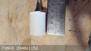
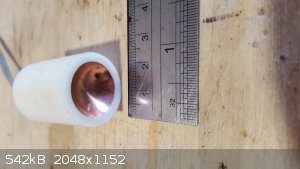
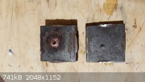
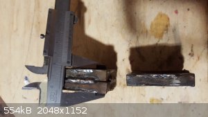
I had 8 grams of plastic etn that was getting old so i tried a 19mm dia hybrid efp i used 80mm standoff and my standard ebw setup .
I got a nice shaped entry hole and 28mm penetration with a 3mm dia hole, not great but there is .chance of more penetration wit more tests  . .
  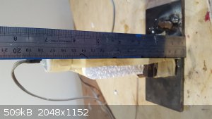 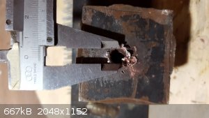 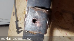 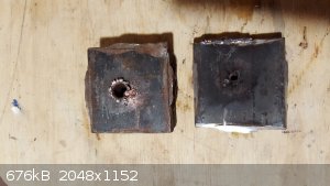  
[Edited on 22-3-2016 by nux vomica]
|
|
|
greenlight
National Hazard
   
Posts: 763
Registered: 3-11-2014
Member Is Offline
Mood: Energetic
|
|
Nice to see another test from you, over an inch of penetration is very good.
The entry hole looks like an EFP hit but the penetration is like the effect from an actual jet.
Is it possible that your device functioned as both at once with a combined effect of a large entry with deep penetration.
Very interesting.
|
|
|
nux vomica
Hazard to Others
  
Posts: 267
Registered: 18-7-2013
Member Is Offline
Mood: No Mood
|
|
Quote: Originally posted by greenlight  | Nice to see another test from you, over an inch of penetration is very good.
The entry hole looks like an EFP hit but the penetration is like the effect from an actual jet.
Is it possible that your device functioned as both at once with a combined effect of a large entry with deep penetration.
Very interesting. |
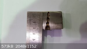
Thanks greenlight , it looks like it is forming a jet but the edges of the disc collapse in and form a small efp at the same time.
I cut the plate stack to show penetration each plate is 10mm thick.
Nux
|
|
|
NeonPulse
Hazard to Others
  
Posts: 417
Registered: 29-6-2013
Location: The other end of the internet.
Member Is Offline
Mood: Isolated from Reality! For Real this time....
|
|
Very nice! I was wondering when this thread would revive. How was it a hybrid?
|
|
|
nux vomica
Hazard to Others
  
Posts: 267
Registered: 18-7-2013
Member Is Offline
Mood: No Mood
|
|
Thanks neon , its has been a bit quiet lately , i called it a hybrid as it should be forming a efp projectile only, but it forms a jetting
affect like a cone shaped liner instead .
So it seems to be in a transition point between a efp and a liner that forms a jetting affect.
This is my other use for hybrid cones.

[Edited on 23-3-2016 by nux vomica]
|
|
|
NeonPulse
Hazard to Others
  
Posts: 417
Registered: 29-6-2013
Location: The other end of the internet.
Member Is Offline
Mood: Isolated from Reality! For Real this time....
|
|
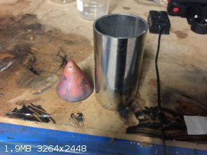
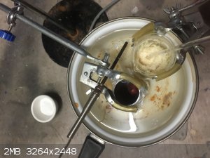
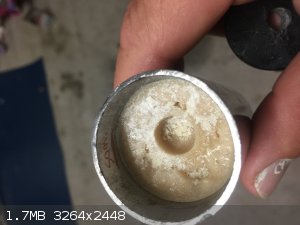
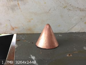
So it's been a while since this thread has had a post so here goes: Recently I did a test of a cyclotol/pentolite composition in a shaped charge. An
electroformed liner I had made some time ago was jb welded into a piece of stainless steel tubing with a wall thickness of 1.5 mm. A snug fitting
plastic cap used on steel tube furniture was the cap and it was filled with steel epoxy putty and drilled dead centre for the cap. The cone thickness
was 1.5mm thick.Also the angle was steeper than I usually go as an experiment. I didn't actually measure it though but I didn't think of that until
after it was in place.oops. I also had annealed the copper first which I also don't usually do either. A bit of 40 mm PVC was standoff and a couple
of wraps of tape around the charge and it fit snugly inside.
I chose a X1.75 CD as the standoff distance this time.
For the filler I decided to use a 75g casting consisting of 40g TNT, 20g RDX and 15g PETN. The fine powder TNT was mixed with the other two
components and this was melted together in a small beaker in a hot water bath with the casing submerged also. The molten mixture was then poured into
the hot casing which was then tapped gently on the floor to release any trapped air bubbles and a small glass test tube was put in the centre held
there with a couple of skewer to make a cap well and then it was allowed to cool slowly in the hot water bath over the next hour and a half.
The heating was gradually bought up over a period of around 20 mins and This was done at no hotter than 84c. There appeared to be little shrinking and
no visible cracking was seen in the cast. An aluminium cap was constructed filled with 1g RDX,300 mg Azo-Clathrate and a further 150 mg lead
styphnate as the igniter to be set off electronically.
|
|
|
| Pages:
1
..
56
57
58
59
60
..
68 |