| Pages:
1
..
11
12
13 |
Belowzero
Hazard to Others
  
Posts: 175
Registered: 6-5-2020
Location: Member Is Offline
Member Is Offline
|
|
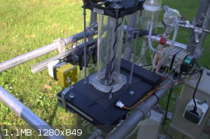
Just wanted to show my nearly completed Pauling furnace.
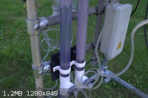
I've added a couple components such as scrubbing 'towers' which are 1.5m long PVC tubes filled with foamed glass beds.
The total capacity of the 2 columns is roughly 1.5L.
Except for the oxidation chain the device is all PVC and HDPE.
Also currently the system runs with 3 peristaltic pumps (the fourth is still giving some problems)
(Currently the pumps are in series which might not be as effective, still have to do some tests.)
Basically there are 2 pump groups which control the circulation for the towers.
Right now it drips, I will need to create a nozzle of sorts to have the liquid spray, the pumps are quite powerful but not very fast.
The chemical resistance is a major plus though.
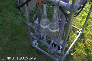
Another new feature are the oxidation chambers, there are 2 oxidation chains consisting of 6 coke bottles which are inverted and glued together, this
gives me rougly 6L of volume per chain.
It is very interesting to see the difference in color per chamber showing that it does indeed oxidize! I didn't expect it to be that clear. The second
chain only has very faint color, providing me with the evidence that a third is probably not required.
Every plant needs a frame!
After looking at all sorts of solutions I finally settled for scaffold components which is very strong and allows any sort of shape.
Only downside is the weight but overall it looks great imo.
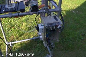
And finally a control box which allows me to switch the components, I left some room to add relais and control the device from a digital controller
such as an Arduino.
Combining this with temperature probes it would allow me to have a dynamic cool-down period.
My old and simple clock switch didn't like switching a NST and died. So this too will have to be done digitally.
I also made a video of the device for those that are interested:
https://www.youtube.com/watch?v=mp_mvHh9ci0


[Edited on 7-9-2021 by Belowzero]
[Edited on 7-9-2021 by Belowzero]
|
|
|
Texium
Administrator
       
Posts: 4675
Registered: 11-1-2014
Location: Salt Lake City
Member Is Offline
Mood: Preparing to defend myself (academically)
|
|
Wow! What a beautiful and professional-looking setup you've made (Coke bottles notwithstanding  ). Looking forward to seeing what kind of output you end up getting once everything is optimized. ). Looking forward to seeing what kind of output you end up getting once everything is optimized.
|
|
|
macckone
Dispenser of practical lab wisdom
    
Posts: 2171
Registered: 1-3-2013
Location: Over a mile high
Member Is Offline
Mood: Electrical
|
|
Looks very professional.
For a home system, the biggest thing I have found is cooling the absorption unit below 21C to liquify the NO2.
Liquid NO2 with air flow quickly absorbs to nitric acid.
Residence time for NO to oxidize to NO2 is the other big one.
I use a 1L mixing chamber before the absorber and an aquarium pump bubbler.
I need to post some pics.
One thing to note is that NO2 is colored but NO is not, so clear may mean you are getting a lot of NO escaping.
|
|
|
Belowzero
Hazard to Others
  
Posts: 175
Registered: 6-5-2020
Location: Member Is Offline
Member Is Offline
|
|
Quote: Originally posted by Texium  | Wow! What a beautiful and professional-looking setup you've made (Coke bottles notwithstanding  ). Looking forward to seeing what kind of output you end up getting once everything is optimized. ). Looking forward to seeing what kind of output you end up getting once everything is optimized.
|
Thanks Texium.
I was indeed wondering how long the coke bottles would last..
The reason I chose PVC for the scrubbers is that according to compatibility charts it can withstand 30% nitric acid for extended periods/permanent.
This is a similar strength to the maximum concentration obtainable via this method.
I can imagine NOx being quite a bit more aggressive, hopefully the inner layer will react to some extend to become "inert".
Quote: Originally posted by macckone  | Looks very professional.
For a home system, the biggest thing I have found is cooling the absorption unit below 21C to liquify the NO2.
Liquid NO2 with air flow quickly absorbs to nitric acid.
Residence time for NO to oxidize to NO2 is the other big one.
I use a 1L mixing chamber before the absorber and an aquarium pump bubbler.
I need to post some pics.
One thing to note is that NO2 is colored but NO is not, so clear may mean you are getting a lot of NO escaping. |
Will look into that, interesting option.
Please do share.
[Edited on 8-9-2021 by Belowzero]
|
|
|
Alkoholvergiftung
Hazard to Others
  
Posts: 198
Registered: 12-7-2018
Member Is Online
|
|
You should bend the jacobsladder like horns of an Ram. It climbs up like in the Frankenstein movies. I ve done it and it build engouh pressure so you
dont need an airpump for the reactor inlet. You hear the "wump, wump , wump". If you have an static burn there is no over pressure and i think you
lose an lot of NO because it stands to long in the arc.
|
|
|
Belowzero
Hazard to Others
  
Posts: 175
Registered: 6-5-2020
Location: Member Is Offline
Member Is Offline
|
|
Quote: Originally posted by Alkoholvergiftung  | | You should bend the jacobsladder like horns of an Ram. It climbs up like in the Frankenstein movies. I ve done it and it build engouh pressure so you
dont need an airpump for the reactor inlet. You hear the "wump, wump , wump". If you have an static burn there is no over pressure and i think you
lose an lot of NO because it stands to long in the arc. |
Well I am going to need airpressure to move the gas through the system however it does not need to flow directly through the flame as it does now and
as Pauling intended it (the collapsing and reestablishing of the arc is what produces the most NOx according to the multiple sources hence 'blowing
out' the arc.)
Could you please explain in more detail what you mean by horns of a ram? I never watched the Frankenstein movies tbh.
There are too many ways of interpreting your description or maybe I am too stupid.
|
|
|
Alkoholvergiftung
Hazard to Others
  
Posts: 198
Registered: 12-7-2018
Member Is Online
|
|
When you bend the ends of the jacobsladder in an halfcircle so the arc is disruptet if you dont bend it it stands on the top. Ive done it without
bending and the arc moved slowly to the top but if you bend it it rises continuously (and realy fast) and disconnect an the top.The pressure was
enough to bubble the gases throught water if you use an standig arc you need an airpump. oh and i used more than 45degree angle around 65.
|
|
|
Belowzero
Hazard to Others
  
Posts: 175
Registered: 6-5-2020
Location: Member Is Offline
Member Is Offline
|
|
Thanks for clarifying, Ill try bending some copper pipe in such a shape.
Anything thinner just doesnt last, fun for demonstrations not for continuous production.
|
|
|
Alkoholvergiftung
Hazard to Others
  
Posts: 198
Registered: 12-7-2018
Member Is Online
|
|
Dont know if it helps you but my reactor was an 30mm diameter test tube and i made an hole in the bottom with an small gasburner so the gas flow was
from bottom to top. I seald it with two componets glue. Was only test reactor with 50w arc. But it worked. My next try (when i have time) is tu make
an aluminium cooling body like an sleeve over the test tube. Turned from an aluminium roundbar. Haber wrote that if the reaction chamber would be out
of metal the yield would much higher. I have no idea how he wanted to prevent short cuts from the electricity. But the sleeve would my solution.
|
|
|
Texium
|
Thread Moved
19-11-2023 at 09:52 |
akmetal
Harmless

Posts: 43
Registered: 20-11-2023
Member Is Offline
|
|
I have a fully functional reactor but I am working on increasing the efficiency so I can provide feed stock for pure nitric for semi commercial
purposes.
I also have to stop the gas leaks - I am either going to buy an eductor or design one.
|
|
|
Rainwater
National Hazard
   
Posts: 990
Registered: 22-12-2021
Member Is Offline
Mood: Break'n glass & kick'n a's
|
|
https://www.sciencemadness.org/whisper/viewthread.php?tid=15...
here is a 3d models for a simple 'eductor' also know as Venturi valves.
"You can't do that" - challenge accepted
|
|
|
akmetal
Harmless

Posts: 43
Registered: 20-11-2023
Member Is Offline
|
|
I found this cool video - https://www.youtube.com/watch?v=0yK4Mzv7ei0
Its basicly just a venturi with a break in it to exploit the vacuum pressure section where the process gas enteres. I would think that you could just
do a finite element analysis on a venturi for a gas and then find the lowest pressure region and thats where your break is? But then how far do you
pull back the nozzle?
I reached out for a quote from Fox Venturi and am a little concerned the price point is going to have me building my own .....
|
|
|
akmetal
Harmless

Posts: 43
Registered: 20-11-2023
Member Is Offline
|
|
Does anybody know how big the oxidation reactor needs to be in the Birkeland Eyde process.
Turns out I think I was over cooling my NO so when it was entering the oxidation chamber it was way to cold. My peltier cooling system and exchangers
get WAY to cold so I think I just need a length of glass tube and that's probably it and then use all the cooling for the absorption bath with frit.
https://pubs.rsc.org/en/content/articlehtml/2021/ee/d0ee0376...
[Edited on 21-8-2024 by akmetal]
|
|
|
UndermineBriarEverglade
Hazard to Self
 
Posts: 57
Registered: 13-6-2024
Member Is Offline
|
|
I have been attempting to recreate WGTR's reactor: a low-current HV supply that clears the way for a low-voltage high-current arc. I am using an eBay stun gun module (output ~5KV)
for the HV. The low side is mains voltage through a bridge rectifier. My high-voltage arc REALLY wants to short through the rectifier instead of
arcing across the main contacts. I added a wire-wound inductor with no evident change. What's the solution here?
Removing the bridge rectifier, I've been able to start an arc with 120VAC, but only at gaps small enough that the arc can sustain itself without HV.
It'll keep going until it pops the breaker. Putting a magnet next to the HV arc doesn't seem to do anything, but I haven't been able to test with the
low-voltage arc.
|
|
|
Twospoons
International Hazard
    
Posts: 1353
Registered: 26-7-2004
Location: Middle Earth
Member Is Offline
Mood: A trace of hope...
|
|
With so few details I'm guessing here, but do you have a capacitor on the DC side of your bridge rectifier? I'm guessing not. You need that in order
for the inductor to do anything - it forms a low-pass filter in combination with the capacitor. Also the inductor construction is important - it must
withstand your HV without breaking down internally (i'd suggest aiming for 2x your HV voltage) and you also need to minimise self-capacitance. I'd
suggest using a ferrite rod with a single layer of wire wound on it, then pot it in epoxy, varnish or oil. You will need to insulate the ferrite with
several layers of plastic tape too.
Helicopter: "helico" -> spiral, "pter" -> with wings
|
|
|
UndermineBriarEverglade
Hazard to Self
 
Posts: 57
Registered: 13-6-2024
Member Is Offline
|
|
Correct, no capacitor on there. I figured pulsed DC would make the arc more likely to extinguish, and I don't have enough 170V capacitance to
significantly smooth the expected load anyway. If he was using an off-the-shelf 150V supply it presumably would have included filter caps, but only
rated for low voltage. But possibly it was homemade? His first update video is too low-res for me to read the component values but shows three huge caps in series that look like they're in
the low voltage circuit. He wrote few details about the electrical side. The text indicates the inductance was parasitic, although you can see the
electrode wires are bent into coils either to make air-cored inductors or to dissipate heat.
I could stick a microwave cap on the low-voltage side. My inductor doesn't appear to be breaking down, but it is also only around 8uH or so. 22AWG
around an iron rod, any inductor will have to be pretty beefy to stand up to the arc current.
[Edited on 2024-11-9 by UndermineBriarEverglade]
|
|
|
Twospoons
International Hazard
    
Posts: 1353
Registered: 26-7-2004
Location: Middle Earth
Member Is Offline
Mood: A trace of hope...
|
|
100nF to 1 uF would likely be enough capacitance. Its not going to do any smoothing of the LV, but it will help prevent the HV high frequency pulse
from reaching the diodes.
An iron rod is not a good idea - being conductive it looks a "shorted turn" in the inductor ( by transformer coupling). This makes it lossy, and it
will heat up with your half-sine LV current. Ferrite is much better. Or you can use iron laminates from a transformer.
Helicopter: "helico" -> spiral, "pter" -> with wings
|
|
|
UndermineBriarEverglade
Hazard to Self
 
Posts: 57
Registered: 13-6-2024
Member Is Offline
|
|
I added a microwave capacitor. First, I tried laying out the electrodes like WGTR did (top circuit). The high-voltage arc jumps to the low-voltage
electrode, but charges the capacitor rather than arcing across the main electrodes.
Then, I laid out the electrodes so that the paths cross each other (bottom circuit). But this isn't enough to start the low-voltage arc.
Has anyone else gotten this type of piggyback arc design working?

|
|
|
wg48temp9
National Hazard
   
Posts: 787
Registered: 30-12-2018
Location: not so United Kingdom
Member Is Offline
|
|
Quote: Originally posted by UndermineBriarEverglade  | I added a microwave capacitor. First, I tried laying out the electrodes like WGTR did (top circuit). The high-voltage arc jumps to the low-voltage
electrode, but charges the capacitor rather than arcing across the main electrodes.
Then, I laid out the electrodes so that the paths cross each other (bottom circuit). But this isn't enough to start the low-voltage arc.
Has anyone else gotten this type of piggyback arc design working?
|
First, please note: Your schematic has no ballast to limit the arc current.
It is difficult to get a spark gap switch using a trigger electrode to operate reliably with such low voltages (about 150v) across the main
electrodes.
Plasma cutters and "no touch start" arc welders use a series HV high frequency trigger pules added to open circuit voltage of the plasma cutter or
welder output voltage to start the arc.
Search for DIY HF arc start for more info.
I am wg48 but not on my usual pc hence the temp handle.
Thank goodness for Fleming and the fungi.
Old codger' lives matters, wear a mask and help save them.
Be aware of demagoguery, keep your frontal lobes fully engaged.
I don't know who invented mRNA vaccines but they should get a fancy medal and I hope they made a shed load of money from it.
|
|
|
| Pages:
1
..
11
12
13 |