dhaffnersr
Harmless

Posts: 30
Registered: 29-3-2016
Location: Hopewell VA
Member Is Offline
Mood: always cool and calm...
|
|
Homemade spectrometer analysis of rhodamine b
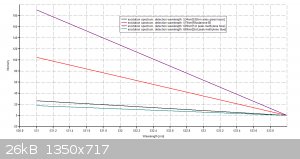
I have to repost this again since the images were deleted by the moderator previously by mistake, so here goes, I built my own spectrometer so I could
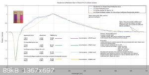
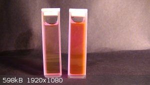
do spectral analyzing of organic compounds from a kit by Plab, and here are some of those results:
|
|
|
Ozone
International Hazard
    
Posts: 1269
Registered: 28-7-2005
Location: Good Olde USA
Member Is Offline
Mood: Integrated
|
|
While that is cool, I think you should talk more about your design. Both rhodamine B and methylene blue have very distinct VIS spectra (both
absorbance and emission). Perhaps more information would open a discussion on hacking a monochromator (1 for absorbance, 2 for emission) in order to
try and get a recognizable spectrum?
O3
[Edited on 29-3-2016 by Ozone]
-Anyone who never made a mistake never tried anything new.
--Albert Einstein
|
|
|
dhaffnersr
Harmless

Posts: 30
Registered: 29-3-2016
Location: Hopewell VA
Member Is Offline
Mood: always cool and calm...
|
|
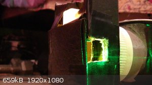
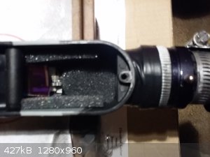
Hey ozone, yes you are right about the distinct peaks of rhodamine b, my spectrometer design is still a work in progress this is the specs of my
current set up;
1) Spectrometer bandwidth = 18
2) Slit width = 0.18mm
3) Slit length = 19mm
4) Distance of slit to camera = 48mm
5) Cuvette distance to slit = 29mm
6) Cuvette distance to camera = 78.13mm
7) Width of DVD grating = 17.90mm
8) DVD piece used is 8.5gb - ruling density = 2770 lines/mm = 0.36mm groove spacing = 360nm
9) Camera type (board level cmos sensor sensitivity- 400nm - 650nm
I just redesigned the cuvette holder so it can accommodate a notch filter so I can eliminate the laser signal which right now is drowning out a lot of
the weaker raman signals. I'll post some more pics of the redesign soon.
thanks Dave H
[Edited on 30-3-2016 by dhaffnersr]
|
|
|
gatosgr
Hazard to Others
  
Posts: 237
Registered: 7-4-2015
Member Is Offline
Mood: No Mood
|
|
Sorry but how does raman "signals" relate?
|
|
|
dhaffnersr
Harmless

Posts: 30
Registered: 29-3-2016
Location: Hopewell VA
Member Is Offline
Mood: always cool and calm...
|
|
I need the "notch" filter because it eliminates the laser line which causes what is called "rayleigh light scattering." The "weaker" raman signals are
mixed in with the laser light, so in order to get a clean signal I need to filter the laser line out so the rest of the collected light can get to the
detector.
The way I have it set up now is fine, mainly for UV spectrometry, but I have modified it to be a raman spectrometer as well.
I'm uploading a pic of a spectrum I did today of rhodamine b with my green laser and although you can clearly see the fluorescent signiture, you can
also see the laser line to the left, very naughty!

|
|
|
gatosgr
Hazard to Others
  
Posts: 237
Registered: 7-4-2015
Member Is Offline
Mood: No Mood
|
|
Looks nice, I didn't know you can get raman signals with a UV spectometer , the rayleigh scattering depends on the optical equipment you're using.
|
|
|
dhaffnersr
Harmless

Posts: 30
Registered: 29-3-2016
Location: Hopewell VA
Member Is Offline
Mood: always cool and calm...
|
|
| Quote: |
Looks nice, I didn't know you can get raman signals with a UV spectometer , the rayleigh scattering depends on the optical equipment you're using.
|
I didn't know it either until I started tweaking it, using different DVD gratings and optical filters, still I can only go as far as the limits of the
cmos camera which is about 400nm to 650nm spectrum range.
|
|
|
aga
Forum Drunkard
    
Posts: 7030
Registered: 25-3-2014
Member Is Offline
|
|
I would like more details please.
Would you (please) describe the project in enough detail so that we could all copy it ?
|
|
|
Velzee
Hazard to Others
  
Posts: 381
Registered: 19-8-2015
Location: New York
Member Is Offline
Mood: Taking it easy
|
|
I should probably research all of this so I can know what this means...
Check out the ScienceMadness Wiki: http://www.sciencemadness.org/smwiki/index.php/Main_Page
"All truth passes through three stages. First, it is ridiculed. Second, it is violently opposed. Third, it is accepted as being self-evident."
—Arthur Schopenhauer
"¡Vivá Cristo Rey!"
—Saint José Sánchez del Río |
|
|
Ozone
International Hazard
    
Posts: 1269
Registered: 28-7-2005
Location: Good Olde USA
Member Is Offline
Mood: Integrated
|
|
OK. That makes more sense. Raman. It would have been helpful to have mentioned that in the beginning. 532nm is a sensible wavelength in terms of shift
and photochemical behavior. And, Nd:YAG KTP DPSS lasers are fairly easy to come by (for now, anyway).
O3
[Edited on 31-3-2016 by Ozone]
-Anyone who never made a mistake never tried anything new.
--Albert Einstein
|
|
|
dhaffnersr
Harmless

Posts: 30
Registered: 29-3-2016
Location: Hopewell VA
Member Is Offline
Mood: always cool and calm...
|
|
| Quote: |
OK. That makes more sense. Raman. It would have been helpful to have mentioned that in the beginning. 532nm is a sensible wavelength in terms of shift
and photochemical behavior. And, Nd:YAG KTP DPSS lasers are fairly easy to come by (for now, anyway).
|
Hey Ozone, your right, for now green lasers are easy to come buy until the fed's ban those too!
|
|
|
dhaffnersr
Harmless

Posts: 30
Registered: 29-3-2016
Location: Hopewell VA
Member Is Offline
Mood: always cool and calm...
|
|
| Quote: |
I would like more details please. Would you (please) describe the project in enough detail so that we could all copy it ?
|
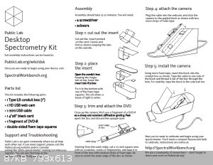
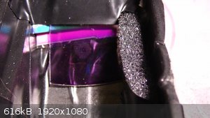
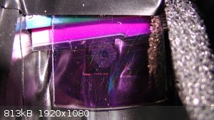
Hey aga, here are the original kit instructions for building the spectrometer and pics of my modifications, also I'll post the specs on my set up as
it stands now.
1) Spectrometer bandwidth = 18
2) Slit width = 0.18mm
3) Slit length = 19mm
4) Distance of slit to camera = 48mm
5) Cuvette distance to slit = 29mm
6) Cuvette distance to camera = 78.13mm
7) Width of DVD grating = 17.90mm
8) DVD piece used is 8.5gb - ruling density = 2770 lines/mm = 0.36mm groove spacing = 360nm
9) Camera type (board level cmos sensor sensitivity- 400nm - 650nm
1-5 nm spectral resolution
20-30 samples per second
   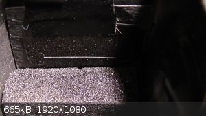 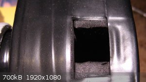 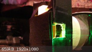
|
|
|
gatosgr
Hazard to Others
  
Posts: 237
Registered: 7-4-2015
Member Is Offline
Mood: No Mood
|
|
And here are instructions https://www.youtube.com/watch?v=fl42pnUbCCA
|
|
|
dhaffnersr
Harmless

Posts: 30
Registered: 29-3-2016
Location: Hopewell VA
Member Is Offline
Mood: always cool and calm...
|
|
A very clever technique on removing the unwanted layers from the DVD piece, thanks for posting the video.
|
|
|
gatosgr
Hazard to Others
  
Posts: 237
Registered: 7-4-2015
Member Is Offline
Mood: No Mood
|
|
Have you used it for anything more than rhodamine?
|
|
|
dhaffnersr
Harmless

Posts: 30
Registered: 29-3-2016
Location: Hopewell VA
Member Is Offline
Mood: always cool and calm...
|
|
| Quote: |
Have you used it for anything more than rhodamine?
|
Oh yeah, I've used it with a 405nm UV laser also for Eosin y and some petroleum products. Its just taken awhile to get it just right, the reason I'm
working with dyes at this moment, is because there are NIST standards that I can use to plot calibration curves and make sure I'm at least close to
those standards for the various dyes.
That's how I'll know I have a good set up.
|
|
|
dhaffnersr
Harmless

Posts: 30
Registered: 29-3-2016
Location: Hopewell VA
Member Is Offline
Mood: always cool and calm...
|
|
New upgrade for my spectrometer
New upgrade for my spectrometer
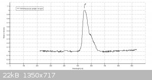
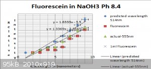
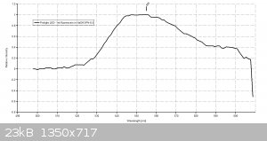
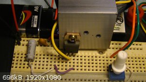
I redesigned the LED driver circuit for the prolight UV LED I use for my spectrometer, and here are the schematics and some pics of the circuit in
operation and some work I'm doing with Fluorescein:
     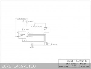 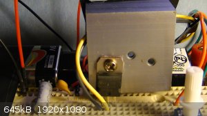
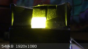
|
|
|
dhaffnersr
Harmless

Posts: 30
Registered: 29-3-2016
Location: Hopewell VA
Member Is Offline
Mood: always cool and calm...
|
|
Rev 3.0 to my LED driver circuit...
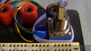
I revised my schematic to incorporate the bourns POT to control the main voltage and use the trimmer POT to control voltage at the hundreth of a volt
range.
specs on the bourns POT:
Bourns POT 82A1AC28BA0728.
1/4" diameter flatted shaft. 10K Ohms, linear taper. 2W, single-turn cermet potentiometer.3/8" diameter threaded bushing. New pot, prepped with three
6" wire leads.
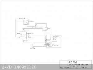
|
|
|