| Pages:
1
2
3
4
..
6 |
unome
Hazard to Others
  
Posts: 134
Registered: 17-10-2009
Member Is Offline
Mood: No Mood
|
|
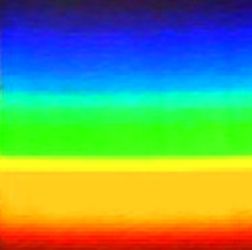
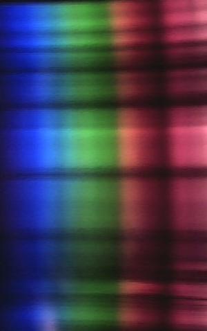
Nother double post, but I thought I'd post this - it is the primary spectrum from a new, tungsten filament halogen bulb resolved over a reflective DVD
grating (the wooden one I built earlier).
I cleaned the pic up (ie. took a short section out of it that contained the cleanest spectrum, removed noise, adjusted the brightness, etc.).
Now I just have to work out how to get that program so I can get a histogram of it
|
|
|
Sedit
International Hazard
    
Posts: 1939
Registered: 23-11-2008
Member Is Offline
Mood: Manic Expressive
|
|
Just a couple thoughts unome, first off as far as removing the coating from a CD this can be done with sticky tape. Just press it on firmly on the
silver and peal off the coating.
Also as N_I noted DVD-R will produce a better quality then CD. An old Blue-ray disk should produce a finer quality then both of these by far.
For a diffraction grating look into childrens "X-ray" vision glasses that produce the rainbow like effects around ones hand. These are straight lined
diffraction gratings and I think sooner or later the curve of the CD lines may interfere with data decoding producing a lower quality signal unless
your retrieving pinpoint accuracy.
Knowledge is useless to useless people...
"I see a lot of patterns in our behavior as a nation that parallel a lot of other historical processes. The fall of Rome, the fall of Germany — the
fall of the ruling country, the people who think they can do whatever they want without anybody else's consent. I've seen this story
before."~Maynard James Keenan
|
|
|
un0me2
aliced25 sock puppet
  
Posts: 205
Registered: 3-2-2010
Member Is Offline
Mood: No Mood
|
|
Yeah those kids gratings look alright - for the moment I'm looking into RGB ==> Wavelength conversion (ie.nm), the DVD diffraction grating seems to
be working quite well enough for the present, when I start getting the spectra from the spectrometer popping itself up (without additional interaction
from the user) then I'll start looking into the use of proper diffraction gratings - I'm thinking of the gel-type on a aluminium background (pretty
much what I'm using with the CD/DVD's now, but straight lines).
I'm interested to see that the instructables model has the same (or essentially the same) spectra from a halogen desk lamp, which means the
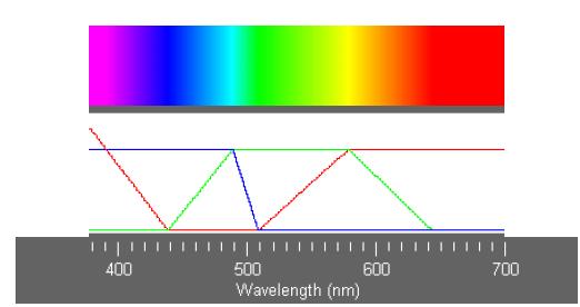
RGB section is working, now to convert that to wavelengths programatically (not so trivial - see the attached jpeg - shamelessly stolen from http://www.philiplaven.com/p19.html)
There are ways to do it, it is just deciding which is going to work best with logic chips and the drivers involved. In terms of what is necessary, we
know the steps that have to be taken and in what order. One of the issues is that fortran is the program of choice (and I have no knowledge of it).
[Edited on 16-2-2010 by un0me2]
|
|
|
Vogelzang
Banned
Posts: 662
Registered: 26-4-2008
Member Is Offline
Mood: No Mood
|
|
Kewl spectroscopics might be interested in this.
http://www.google.com/patents?id=lTEvAAAAEBAJ&printsec=a...
|
|
|
Sedit
International Hazard
    
Posts: 1939
Registered: 23-11-2008
Member Is Offline
Mood: Manic Expressive
|
|
The program of choice is Fortran but they also include the BASIC code and the C code as well which would be my first choice. I would honestly work
with BASIC as long as you have access to the ports needed to work out kinks and be able to build a quick program to test any theorys I had in mind and
altering it to suit my needs. Then I would code the finish product in C++.
Unome would you care to PM me and explain more clearly what you need done.
Knowledge is useless to useless people...
"I see a lot of patterns in our behavior as a nation that parallel a lot of other historical processes. The fall of Rome, the fall of Germany — the
fall of the ruling country, the people who think they can do whatever they want without anybody else's consent. I've seen this story
before."~Maynard James Keenan
|
|
|
unome
Hazard to Others
  
Posts: 134
Registered: 17-10-2009
Member Is Offline
Mood: No Mood
|
|
I'm working on a new & better model (crossed fingers), which will allow me to mount a 7-LED torch (un-fucking-believably bright) on the stage,
then a cuvette, then the spectrometer.
As to the lines, I took it somewhere else today (just the spectrometer, not the camera) and found some varied light sources, with DISTINCT narrow
lines. I'll try and install the cam on my laptop and see if I can do better once I get the new version up and running.
PS WE BADLY NEED SOFTWARE
|
|
|
a_bab
Hazard to Others
  
Posts: 458
Registered: 15-9-2002
Member Is Offline
Mood: Angry !!!!!111111...2?!
|
|
I didn't read all the thread but here is what I know. I may repeat what others have said so excuses 
Since I'm doing some holography I know what a good laser means.
For a regular green laser as a pointer or a module, not only you may have lots of residual IR from the pumping diode, but there are lots of mode
hoppings too (changes in the frequency of the laser) and power levels. That means your laser is not purely 532 but there are residual lines as 532.01
and so; they come directly from the IR pumping diode and will generate "parasitic" Raman lines too. So we have to get rid of these.
There are a few lasers on the market for 532 nm that are "single mode". Such a laser is required by Raman spectroscopy, confocal microscopy, citology
(devices for cells counting), DNA sequencing etc. Such a laser used to cost a fortune (at least 15-20 k$ new) and they still cost about that much. The
reason is that they replace the gas lasers; at 3000-5000 hours an Ar ion laser needs a tube refill, which is very costly (thousands of bucks) while
these lasers are supposed to last at least 7-10000 hours with the same power levels. The power supply requirements are also very different; an Ar ion
laser would suck some 4-10 kW/h, while a solid state laser less than 0.1 Kw (depending on the type).
The good news is that these expensive solid state lasers started to pop as a surplus since 2005 or so, and they are not very difficult to find.
Moreover, the price is way lower than what they used to cost.
I don't know anything about the power requirements for a homemade Raman spectroscope, but I feel like 5-10 mW would do it (the first ever documented
Raman spectroscope was made by a (very smart) girl and she used a 5 mW green laserpoiter only to see that the lines she got were "multiple" due to the
multimode low quality laser - the link may have been already posted).
Nowadays (year 2010) a 100-150 mW green stabilized laser would be like 1000-2000 bucks, while a 50 mW can go down to 400$. There are even 10 mW
versions for much cheaper as here: http://cgi.ebay.com/Coherent-215M-laser-10-Mw-532nm-excelent...
These lasers require very precise alignment of the optics, an extremely high quality TEC (thermoelectric controller) that stabilises the laser head
within 0.001 degrees C, special components, ring resonator design etc. To give you an idea, the warmp time for these lasers is about two minutes;
after that single line operating mode is achieved.
As about the 405 nm blueray diodes - they are far worse than a measly red laser pointer in terms of spectral stability; they barely have a coherence
of 1-2 mm so they mod hopp like a bunny shot in the balls. I really doubt they can be used for Raman spectroscopy in an efficient mode.
|
|
|
Polverone
Now celebrating 21 years of madness
        
Posts: 3186
Registered: 19-5-2002
Location: The Sunny Pacific Northwest
Member Is Offline
Mood: Waiting for spring
|
|
Quote: Originally posted by a_bab  |
Since I'm doing some holography I know what a good laser means.
For a regular green laser as a pointer or a module, not only you may have lots of residual IR from the pumping diode, but there are lots of mode
hoppings too (changes in the frequency of the laser) and power levels. That means your laser is not purely 532 but there are residual lines as 532.01
and so; they come directly from the IR pumping diode and will generate "parasitic" Raman lines too. So we have to get rid of these.
There are a few lasers on the market for 532 nm that are "single mode". Such a laser is required by Raman spectroscopy, confocal microscopy, citology
(devices for cells counting), DNA sequencing etc. Such a laser used to cost a fortune (at least 15-20 k$ new) and they still cost about that much. The
reason is that they replace the gas lasers; at 3000-5000 hours an Ar ion laser needs a tube refill, which is very costly (thousands of bucks) while
these lasers are supposed to last at least 7-10000 hours with the same power levels. The power supply requirements are also very different; an Ar ion
laser would suck some 4-10 kW/h, while a solid state laser less than 0.1 Kw (depending on the type).
|
I am really interested in this. I found some red diode lasers that claimed to be "single mode" for under $100 new. But the only "frequency stabilized"
red diode lasers I found cost more than $1000 new. I had come to think that a multi-mode laser emits at multiple frequencies simultaneously, a single
mode laser emits at only one frequency at a time, and a frequency stabilized laser emits at one frequency for an extended period of time. Are these
really equivalent items, with vastly different market segment targets, or is a frequency stabilized laser more involved than a single-mode laser?
PGP Key and corresponding e-mail address
|
|
|
un0me2
aliced25 sock puppet
  
Posts: 205
Registered: 3-2-2010
Member Is Offline
Mood: No Mood
|
|
The mode-hopping, etc. should have minimal effect given that we are using a laser-line filter (a proper one) to keep the wavelength within reasonable
bounds, then a steep-cut-on filter (comes on @ 550nm all the way to the NIR) which comes on, cutting off all stray light that made it through the line
filter and several nm above that as well.
I'm actually beginning to wonder how Dr Raman did it, He sure didn't use a laser, so that means he merely used a strong source of monochromatic
light.... What about using a blue/green (they are relatively narrow wavelengths) LED torch and focusing the light through optical fiber? Put the
laser-line/narrow bandpass filters between the light source and the collimator and we'd be dealing with a strong-source of a narrow-wavelength light,
which we can then block using an edge filter, thus enabling the collection of ONLY the Stokes-shifted wavelengths.
As such an approach would have a wider beam, still collimated & coherent, therefore more molecules should be excited and give off
Stokes/Anti-Stokes responses, while the light source would be several magnitudes cheaper to run, a lot easier to design, lack the massive power draw
of lasers and not have the need for a massive heat sink.
It is possible to use 10 LEDs and get light on par with what is expected from a 100W beam. Put that through a lens and then into Fiber and it will be
extremely strong light. Matter of fact, anyone got a cheap and dirty way of doing this?
[Edited on 17-2-2010 by un0me2]
|
|
|
a_bab
Hazard to Others
  
Posts: 458
Registered: 15-9-2002
Member Is Offline
Mood: Angry !!!!!111111...2?!
|
|
This will answer all of your questions: http://pagesperso-orange.fr/redlum.xohp/laser/spectra.html
Just browse that site, the guy really knows it's stuff. He tested lots of red and blue diodes and the measurements are very cool.
"frequency stabilized" may not be "single mode". It may have all kinds of stabilizers, but "single-mode" is in theory only a line on the spectrum.
The problem comes when getting a chinese laser claimed to be single mode, and you eventually find out that it has another line of "less than 5% of the
total power, very difficult to remove". That would make it unsuitable for many things, including holography.
A good single mode laser shouldn't have more than 1% extra lines (they should be very very weak). This is for diodes; for gas lasers there are no such
problems. There are power fluctuations issues there.
|
|
|
un0me2
aliced25 sock puppet
  
Posts: 205
Registered: 3-2-2010
Member Is Offline
Mood: No Mood
|
|
Yeah, I grant your point on the lasers, it is factual.
What I am saying is that Sir C.V. Raman managed to win the Nobel Prize in Physics in 1930 WITHOUT using lasers at all. He merely narrowed down the light source to a single wavelength and using massive amounts of it, managed to
obtain the Stokes-Shifted Light arising therefrom (also by blocking the wavelength he irradiated it with).
[Edited on 18-2-2010 by un0me2]
Attachment: Raman.A.New.Radiation.pdf (447kB)
This file has been downloaded 981 times
[Edited on 18-2-2010 by un0me2]
Attachment: Raman.Crystals.and.Photons.pdf (410kB)
This file has been downloaded 1080 times
Attachment: Raman.Krishnan.A.New.Type.of.Secondary.Radiation.pdf (64kB)
This file has been downloaded 960 times
Attachment: Raman.Optics.in.India.The.Spectrosocopic.Behavior.of.Rock.Salt.pdf (743kB)
This file has been downloaded 815 times
Attachment: Raman.Krishnan.A.New.Class.of.Spectra.due.to.Secondary.Radiation.Part.I.pdf (753kB)
This file has been downloaded 1147 times
Attachment: Raman.Nobel.Lecture.pdf (38kB)
This file has been downloaded 846 times
Attachment: Sir.CV.Raman.Biography.pdf (1.6MB)
This file has been downloaded 1026 times
Attachment: The.Raman.Effect.75.Years.Later.pdf (73kB)
This file has been downloaded 971 times
|
|
|
a_bab
Hazard to Others
  
Posts: 458
Registered: 15-9-2002
Member Is Offline
Mood: Angry !!!!!111111...2?!
|
|
The same applies to holography. It was discovered before the laser, and Gabor used the light from a mercury lamp as being the most coherent (whatever
coherence such a light source can have). He also said that a very coherent lightsource was needed for the best result. When the ruby laser came, the
team jumped on it.
The distance measuring using monocromatic light (based on interference phenomena) including first speed of light within 1.5 meters or so accuracy
measurement was also done before the laser. With the laser a 1.5 mm accuracy was possible.
The laser really was something long awated, many already discovered applications needing it.
As about Raman, it is trully a remarcable discovery for the time and they had to readjust the cuantic theory to cover the phenomena: even the
molecules can store energy levels ready to be relesed, same as the electrons with their orbitals.
|
|
|
un0me2
aliced25 sock puppet
  
Posts: 205
Registered: 3-2-2010
Member Is Offline
Mood: No Mood
|
|
But Sir CV Raman did NOT have access to photodiode/LEDs and laser-line filters which could narrow the wavelength of the incident, collimated light to
just over 1nm (1.4nm, eg. 532nm (+/-)0.2nm).... If he had have access to these, I strongly suspect he'd have tried it.  Fucking sight
easier than generating enough light through a monochromator. Fucking sight
easier than generating enough light through a monochromator.
|
|
|
bquirky
Hazard to Others
  
Posts: 316
Registered: 22-10-2008
Location: Perth Western Australia
Member Is Offline
Mood: No Mood
|
|
I suspect (but dont KNOW) that it whould have been done with a gas discharge lamp. and one or two pin holes isolating a single mode. the then week
single beam of light whould have been split appart on a grating and another pinhole used to isolate the required wavelength the very week light
whould have been then passed through the sample and off another grating. onto..... a photographic plate and exposed for quite posibly a very very long
time where the relly relly relly relly week signal might have appeared.
getting any modest amount of power at any wavelength into a single mode is hard.
getting white light into a single mode with enough power to do anything ? thats borderline inposible 
comercialy packaged laser diodes are oftern fiber coupled by simply gluing (or soldering) a cleaved fiber directly onto the diode substrate and hoping
for the best  you will notice that many manufacturers will start getting a bit
fuzzy when it comes to specifying the power output of a single mode fiber coupled laser diode becuse it varies from one device to another. you will notice that many manufacturers will start getting a bit
fuzzy when it comes to specifying the power output of a single mode fiber coupled laser diode becuse it varies from one device to another.
comercialy when people want any serious amount of light down a single fiber they will get a bunch of bigarsed IR laserdiodes and "pump" the multimode
light down a Double clad fiber the fiber itself has two cores a outer multimode core that the pump light bounces around in. and a inner single mode
core that has been doped with some rare earth ions that are able to lase.
so basicly you pump multimode light in one end and it causes the fiber itself to lase and 'new' single mode light comes out the other end.
http://en.wikipedia.org/wiki/Fiber_laser
and it is quite important for analitical spectroscipy becuse multiple modes (light traveling sightly non paralell or not 'Spacialy coherant' http://en.wikipedia.org/wiki/Coherent_light#Spatial_coherenc... ) will cause the spectrum to 'blur' like an image being out of focus.
as for LEDs.. im sorry its reeealy not worth the effort. you just cant couple more than a nano or microwatt down a single mode fiber and evan then the
spectrum of the led whould be so broad that you whould have to throw away most of that if you wanted monocromatic light.
on another note if you are looking for optical components i whould recommend
http://www.thorlabs.com/ <- holographic gratings under $80
and if they dont have what your after try
http://www.edmundoptics.com/
|
|
|
unome
Hazard to Others
  
Posts: 134
Registered: 17-10-2009
Member Is Offline
Mood: No Mood
|
|
Yeah I know what their gratings are worth - I also know what their laser-line/bandpass filters are worth too. The availability of those are what this
is based upon.
Yes, for analytical spectroscopy where the actual spatially coherent, collimated light goes into the device, certainly, lasers are the way, for Raman
- where the light you shine on it is the first thing removed by the filter prior to allowing it to enter the spectroscope? Why would it matter? I'm
not just being a smartarse here, I really do want to know, that is why I am reading the papers on the subject by Raman himself, he did get it to work.
If what you suggest is true, then I see NO reason why filtering the light to a single bandwidth, and passing that light into the solution, would not
have the same effect that we seek, after all it is the photons that we are after and I'm not at all certain that they'll discriminate about the source
of their excitation.
EDIT
In the attached paper, the Author states the following:
Attachment: Koga.Simulation.of.Visible.Spectra.from.Digital.Color.Images.pdf (53kB)
This file has been downloaded 1650 times
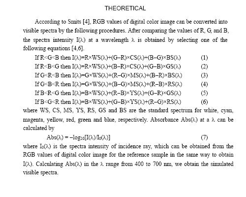
I added some files I found online - but seriously, looking at the problem we have a spectral range of what - 400 (say 420) to 900 at best? So with a
shitty 300K resolution (640x480px) camera, we have 1px per wavelength in the visible spectrum?
So, without allowing for metamers* (other RGB values that give the same perceived color), it would not take a genius to simply sit down and feed a
logarithm to the computer that each specific RGB value for that one pixel is either 000000 or whatever it is supposed to be, up to FFFFFF. That frees
up that part of the system and would allow for rather simple calibration (even with higher resolution cameras, just multiply the number of pixels by
the resolution along the baseline/480).
* With metamers, if they exist, they either equal the DB color for that pixel or they are noise and left out (or they = 000000/black). By averaging
the entire 640 height along that line, we either get a colored pixel, or a black pixel @ that wavelength.
Intensity is another issue altogether, it can be best obtained by the looks of things by using greyscale and histograms. Or by adding the number of
colors = the DB color for that pixel (including metamers that either do or they don't), and use that as a measure of intensity... That does away with
a whole lot of fucking around, and if one were to pull the IR filter off the front of the CCD sensor, then use the long axis to go from 400-1040, or
below 360-1000nm whichever fits better, it still will be only one value per pixel regardless.
Attachment: Smits.An.RGB.to.Spectrum.Conversion.for.Reflectances.pdf (197kB)
This file has been downloaded 1215 times
Attachment: Ward.EydelbergVilshin.Picture.Perfect.RGB.Rendering.using.Spectral.Prefiltering.and.Sharp.Color.Primaries.pdf (1.1MB)
This file has been downloaded 1335 times
Attachment: Wilkie.Larboulette.Purgathofer.Spectral.Color.Systems.and.Appearance.Metrics.for.Fluorescent.Solid.Colors.pdf (583kB)
This file has been downloaded 929 times
Attachment: Li.etal.An.Improved.Method.to.Estimate.Reflectance.Parameters.for.High.Dynamic.Range.Imaging.pdf (777kB)
This file has been downloaded 1005 times
[Edited on 19-2-2010 by unome]
|
|
|
unome
Hazard to Others
  
Posts: 134
Registered: 17-10-2009
Member Is Offline
Mood: No Mood
|
|
The procedure from Sir C.V. Raman himself, was to point a telescope at the sun, then use a monochromator (fucking wild one) which means he used a
colored glass filter to narrow light sufficiently - now a colored glass filter WILL narrow the wavengths of the incident light source, but not
anywhere near as much as the new (and extremely inexpensive) filters, which can narrow it to just over 1nm (about 1/20th of what Raman was working
with). That enables us to better determine the Raman shift - the distance in nm the Stokes-shifted light has moved from the incident wavelength (which
we will know to 1nm). Personally, I feel that pouring several hundred watts of narrow-wavelength LED lights through a 1nm filter then through a
microscope backwards (ie. essentially a telescope), then we will have a very special machine, effectively recreating Sir C.V. Raman's endeavors, using
material that was unthinkable in his day.
Doing the same thing with white leds (which cover the visual spectrum quite well - avoiding the UV and IR ranges), will give a very good VIS-NIR
adsorption spectrometer with lower power costs than current instrumentation. Adding an NIR emitting LED and removing the IR filter off the front of
the CCD/CMOS chip, will allow for even better results.
Working out the spectrometer so that the image fills the viewport/camera lens, thus allowing us to correlate pixels to wavelengths, that is the issue
I am working on at the moment. Having seen several amateur spectroscopes using meters/gauges/rulers to demonstrate the wavelength of the recorded
spectrum, I do believe this is possible and small PCB mounted CCD/CMOS chips, up to 2mp in resolution cost fuck all (mobile phone components - out of
date ones at that).
That will give us the sensor for both the VIS-NIR and the Raman Spectrometer all in one package, CMOS would be preferred (low-power draw).
|
|
|
unome
Hazard to Others
  
Posts: 134
Registered: 17-10-2009
Member Is Offline
Mood: No Mood
|
|
Righto, I just hacked fuck out of a poor defenceless little VX1000, I prised off the little rubber grommets holding on the mounting & then
unscrewed that, then removed the single philips head screw from the rear of the camera, then had to remove the inner grommets from where the mounting
attached... I then unscrewed the lens and removed the small clear-ish piece of glass which is the IR filter. I have now reattached the front fact (and
the lens - although I took the opportunity to remove the fucking annoying call button from on top - it slides out forwards with the front of the
camera off).
I'm going to build a smaller spectroscope this time, with the digicam built in, after the ever elusive VIS-NIR spectra
EDIT - FUCK this goes a LOOOOOONG way into the red
I am using it on the old spectroscope and getting several distinct red bands, fuck all blue....
Now, bar the putting together stage - I've built a wee spectroscope that will fit quite snugly over the front part of both the modified VX-1000 and
the unmodified VX-3000 and once the glue finishes setting, should be able to get some decent spectra and start sorting out some issues I'll be able to get exactly the same resolution with both (640x480 is the max
resolution of the VX-1000 and the minimum resolution of the VX-3000), so it will be interesting to compare the spectra. I'll be able to get exactly the same resolution with both (640x480 is the max
resolution of the VX-1000 and the minimum resolution of the VX-3000), so it will be interesting to compare the spectra.
[Edited on 21-2-2010 by unome]
[Edited on 21-2-2010 by unome]
|
|
|
unome
Hazard to Others
  
Posts: 134
Registered: 17-10-2009
Member Is Offline
Mood: No Mood
|
|
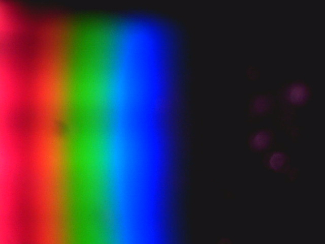
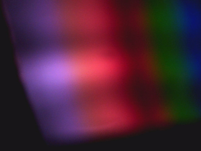
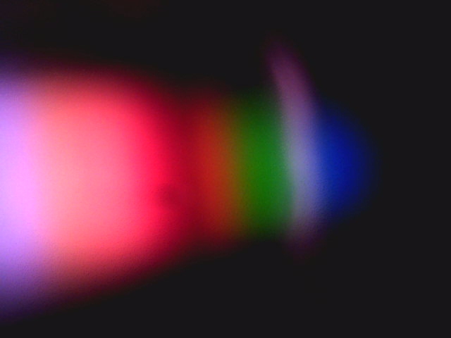
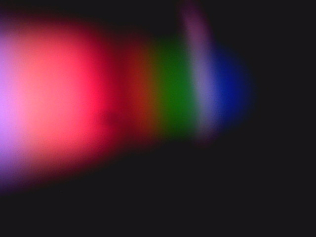
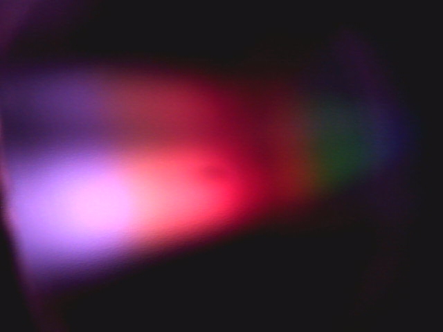
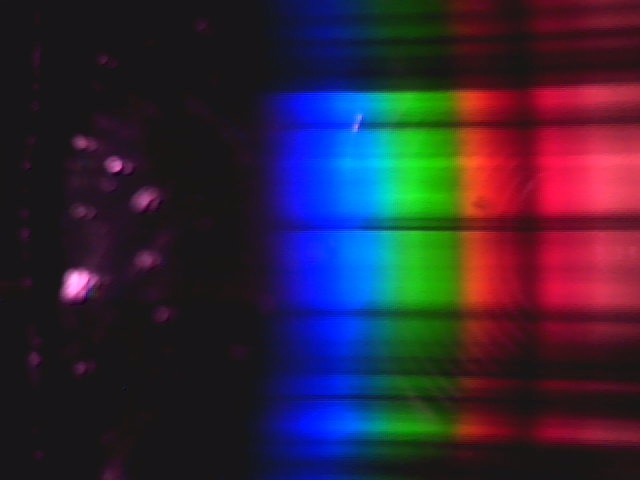
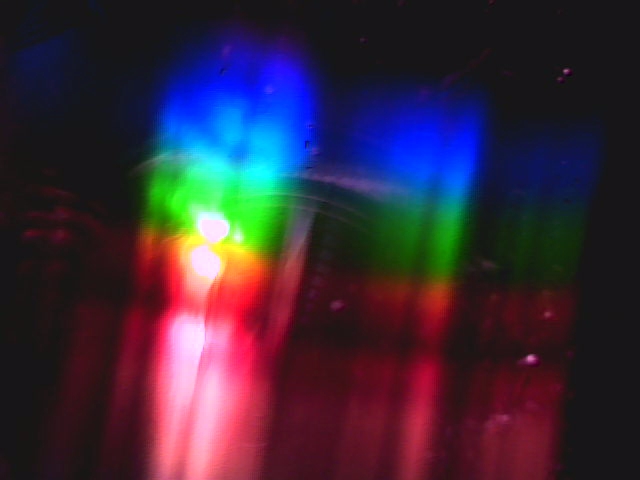
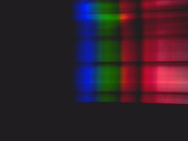
I need to play with this a little more, but that is the SAME lamp as the previous spectra - the red has resolved into at least 3 distinct bands - a
hell of a lot wider than before (dwarfing the blue-green) and that pinkish area at the end of the red spectra I'm assuming is the NIR range?
Righto, I've started to get the slit narrowed down and am getting useable spectra
The latest file is a 640x480 shot from the modified VX-1000. What is intriguing is that it shows the full spectrum - and the spectra I got earlier
with a 1.3mp shot only makes up about 1/2 of that - on the lower resolution shot, we've lost some detail in the bottom part of the spectrum, the
yellow line and some detail from the green, but we have several interesting areas in the newly revealed red, pink and violet half of the spectrum and
I'm seriously wondering how wide this spectrum now is in nm, because it is fully twice the width it was before, or at least appears to be.
I'm going to have to pull the filter out of the VX-3000 just to find out if, with the higher resolution, the detail of the lower end of the spectrum
will still be intact.

PS The spectroscope I used was my own design - it has a wedge of a DVD inset into a hollowed out section of Foam-board (Black foam filled cardboard
sheet). This is set at a 60' angle to the camera. It is attached at the top and bottom to the front and back of the setup - both of which are also
made of foam-board - the front one has a 3cm hole in it to admit the lens of the VX- series cameras. The top, sides and base are all thick black
cardboard and the whole thing is 5.5cm wide, 5cm high & 4cm wide. The slit is 4cm wide (it really ought to be 3cm) and the exposed portion of the
DVD-R (with no bubbles from the cutting - they are covered by the mask) is 4cmx3cm (3cm being the width of the lens and 4cm being the approximate
height of the lens offset at 60').
This latest image is a cropped image - I have spectra going vertically the entire height of the picture, but cannot get it to extend the full width of
the picture... Anyway, I reduced the exposure time significantly and the number of bands appearing now are amazing.
[Edited on 22-2-2010 by unome]
|
|
|
unome
Hazard to Others
  
Posts: 134
Registered: 17-10-2009
Member Is Offline
Mood: No Mood
|
|
I just worked it out - the black segment, taking up about 1/3 of the horizontal segment of the spectrum (ie. before the start of the Visible
Radiation) is the invisible UV radiation which neither I nor the camera can pick up...
I attached the uncleaned spectra (compare to the one above), if I increase the size of the DVD segment and shift the UV spectra out of the view field,
then I'll be able to see all the NIR spectra (which you can only see a part of in those shots).
I also attached a quick design of the spectrometer I am using at the moment (if anyone wants to make it - it is pretty much to scale).
Attachment: spectroscope013.pdf (1.6MB)
This file has been downloaded 934 times
Since we can now measure that which we cannot see, and assign to it the wavelengths we know it corresponds to, then we can also assign the wavelengths
of what we can see, based upon the measurement of what we can't, can't we? Based
solely upon which, using the wavelengths of 0-400 as the invisible half of the spectrum above, then the other half should correspond to 400-800 (or
thereabouts), with the additional 700-800, the NIR range, adding on to the visible spectrum. Based
solely upon which, using the wavelengths of 0-400 as the invisible half of the spectrum above, then the other half should correspond to 400-800 (or
thereabouts), with the additional 700-800, the NIR range, adding on to the visible spectrum.
[Edited on 22-2-2010 by unome]
|
|
|
JohnWW
International Hazard
    
Posts: 2849
Registered: 27-7-2004
Location: New Zealand
Member Is Offline
Mood: No Mood
|
|
That reminds me: yesterday, in the thread http://www.sciencemadness.org/talk/viewthread.php?tid=13183 , which started off about a medical laser, someone said that he found that he can see
into the near infrared down to 804 nm. Is this usual? Also, has anyone here been able to see into the near ultraviolet at shorter wavelengths than 400
nm? If so, the usual quoted 400-700 nm limit of the visible light spectrum band needs to be redefined.
|
|
|
bquirky
Hazard to Others
  
Posts: 316
Registered: 22-10-2008
Location: Perth Western Australia
Member Is Offline
Mood: No Mood
|
|
yes it is often possible to see 800nm I can see down to about 840nm it appears just as faint red.
never tried UV 
|
|
|
un0me2
aliced25 sock puppet
  
Posts: 205
Registered: 3-2-2010
Member Is Offline
Mood: No Mood
|
|
I am currently getting the drivers on this laptop to work and then I'll finally be able to get the spectra from the streetlights and whatever else I
can find of interest...
I'd dearly love to be able to call it a spectrometer, but until it can be used as a means of measuring the wavelengths, its a spectroscope and that is
all
PS Check out the ACTUAL size in these pics
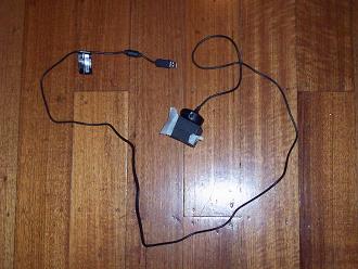 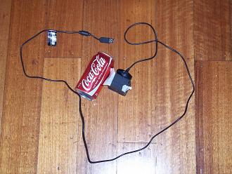
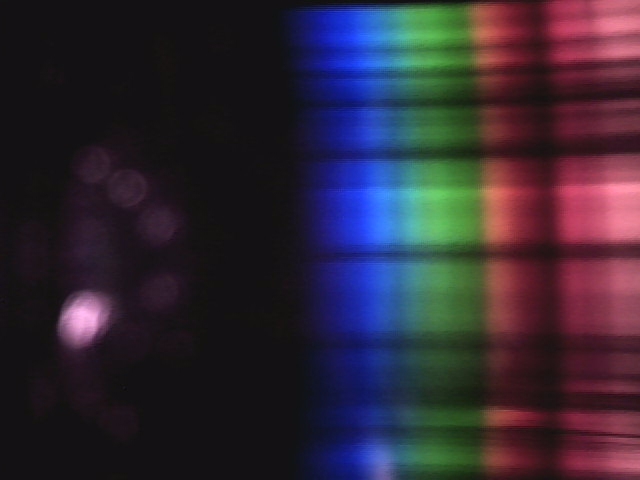
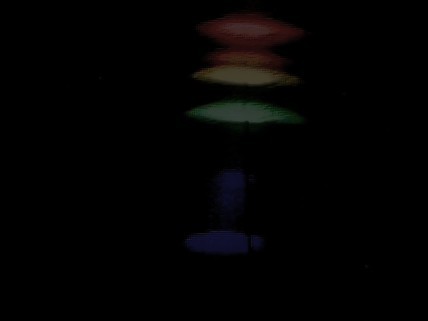
Here is the spectra of the laptop screen
[Edited on 24-2-2010 by un0me2]
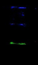
and here is the best shot I could get of the streetlamp (I could SEE far better spectral lines by eye, but fucked if I could get them sharp and thin
like I could see myself). 
[Edited on 24-2-2010 by un0me2]
|
|
|
bquirky
Hazard to Others
  
Posts: 316
Registered: 22-10-2008
Location: Perth Western Australia
Member Is Offline
Mood: No Mood
|
|
|
|
|
bquirky
Hazard to Others
  
Posts: 316
Registered: 22-10-2008
Location: Perth Western Australia
Member Is Offline
Mood: No Mood
|
|
are you pointing the camera at a screen or do you have the light bounce straight off the grating onto the ccd ?
depending on your grating and your desired bandwidth. you may find you can get a higher resolution and sensitivity buy illuminating the ccd directly.
allso for each pixle of the image you are only interested in the absolute intensity not the colour value (spectrometer ccd's are monocrome and some
spectrometers use a physicly rotating mirror grating to scan the spectrum past a single photodetector and detect the spectrum as a function of time )
This means that you will have to add the red green and blue channels of the camera together to try to compensate for the varying sensitivity of each
channel to various wavelengths. a photoedditing program may do this when you convert from 24bit colour to 8 big grey scale.
another thing that may help is saving the data from the camera as a RAW file or a BMP to try to avoid any compression of the image. most compression
will throw away some data not visible to the eye. and some of this information may be what you want !
an interesting thing that you should be able to do with your setup that dosnt require any fancy light sources or optics is oximetry.
http://en.wikipedia.org/wiki/Pulse_oximetry
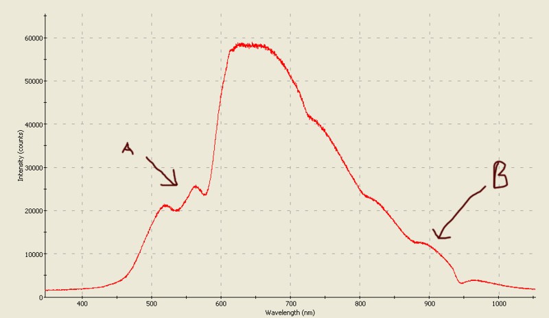
basicly pass regular incandescent light through your finger and you will get a spectrum that looks like this spectrum of my finger.
the little sholder labled a is the absorbsion by the hemoglobin in your blood and the area marked b is another absorbsion point for hemogobin by
looking at the ratio between these two points and comparing it to a empirical table you can tell the oxygen content in the blood.
but more amusingly if you can see the spectrum in real time. the lobe marked A will bob up and down in time with your pulse ! 
|
|
|
un0me2
aliced25 sock puppet
  
Posts: 205
Registered: 3-2-2010
Member Is Offline
Mood: No Mood
|
|
I've tried using DVD/CD's as transmission gratings and had less than impressive results... I'm out in the street with the laptop and the camera trying
to hold onto the Camera/spectroscope and orientate it to where I'm getting the best spectral response through the slit (including trying to modify the
slit width etc.) while also trying to fuck aroudn with the control panel for the camera, playing with exposure, gamma, etc.
When I remove the camera (or more appropriately, when the camera removed itself) and look through the viewport I'm seeing extremely narrow, very well
resolved lines (such as I've come to expect), but capturing them on the CCD is rather more difficult than I had expected. I'll try again
I've got to get a couple of small bulbs, wonder if those little 12V lamps (breakdown ones) they sell at supacheap would work?
|
|
|
| Pages:
1
2
3
4
..
6 |