| Pages:
1
..
3
4
5
6
7
..
48 |
Swede
Hazard to Others
  
Posts: 491
Registered: 4-9-2008
Member Is Offline
Mood: No Mood
|
|
Hi Xenoid... my initial attempts were with a commercial MMO anode offered by Northstar Pyro. The cross section of that Ti strap (gets calculator) is
22.3 mm squared. I have no idea if the strap was Ti or a Ti alloy, and I'm not sure if it makes a difference with regards to conductivity. Anyway, I
used a quality Cu connector... everything was pretty optimal for carrying current, and those straps heated to well above 100C at 50 amps. I found out
only after I attempted to clean a bit of salt creep with a water spray, and the water flashed to a boil.
Things were improved considerably when I mounted a heat sink on the strap. Interestingly, these were the cathode straps. The anode (MMO) straps were
much cooler. I don't pretend to understand the mechanism there, but it was distinct... the all-Ti cathodes were hotter than the Ti + MMO. Anyway, I
just wanted to throw that out as a consideration. Sometimes, commercial MMO cells are designed to carry less current than we are considering pushing
through these setups, and the "choke point" seems to be the hanger cross section, between the Cu power cables, and the immersed electrode.
Dann2, I'm using a homemade spot welder now. Previously, I had been using a TIG welder on the all Ti cathodes that I had been making, and it was
working fine, but I had not tried TIG welding MMO plate or mesh. When my mesh arrived, I dusted off the spot welder to see if it would work. I first
tried it on two pieces of Ti and was stunned that it worked as well as it did. For the MMO mesh, I scraped the coating off the mesh junctions, the
fat areas where the rows meet, on the areas under the strap; cleaned it a bit with alcohol, and fired away, and it worked very well. Just one weld
was secure, and a typical strap to mesh interface is about 15 separate welds. It's clean and fast, no overheating, and appears to be a good way if an
experimenter is doing a considerable quantity of these.
Here is the spot welder:

My talents lie more in fabrication than the chemistry behind this process, although I do have a chemistry background, and am trying to catch up on the
many years of effort by dedicated hobbyists to produce a simple and cheap anode for perchlorate production.
|
|
|
Xenoid
National Hazard
   
Posts: 775
Registered: 14-6-2007
Location: Springs Junction, New Zealand
Member Is Offline
Mood: Comfortably Numb
|
|
Huh! Tried to edit my post and it was deleted!!!
Anyway the gist of it was;
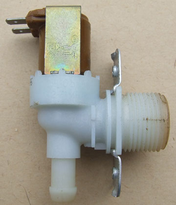
I have a whole bunch of these 24V water inlet solenoid valves which I got from defunct electronic drive washing machines. They are rated at 60oC and
0.2 - 10 bar. They appear to be made from glass reinforced nylon. They are probably not suitable for concentrated acid but should be OK for dilute
dosing, say in the pH range 3 to 7. The outlet (cell inlet) will need to be connected to some narrow bore tubing to restrict flow.
[Edited on 23-10-2008 by Xenoid]
[Edited on 23-10-2008 by Xenoid]

|
|
|
dann2
International Hazard
    
Posts: 1523
Registered: 31-1-2007
Member Is Offline
Mood: No Mood
|
|
Hello,
Article on Graphite erosion attached.
It discusses the chemistry involved.
Dann2
and then I thought why not, A bit of dreamy flower power.
The white things in the pic. are butterflys.
so I post:
It from a Russion republic where their booster rockets/tanks etc fall off their space rockets they are launching. They are scavanged by locals, or not
no locals. Worth a fortune as there are made from Ti, Nb, Hf etc etc and big too.
From Magnum photo's.
[Edited on 23-10-2008 by dann2]
Attachment: Graphite wear in Chlorate process.pdf (578kB)
This file has been downloaded 2012 times
|
|
|
dann2
International Hazard
    
Posts: 1523
Registered: 31-1-2007
Member Is Offline
Mood: No Mood
|
|
and again

|
|
|
Xenoid
National Hazard
   
Posts: 775
Registered: 14-6-2007
Location: Springs Junction, New Zealand
Member Is Offline
Mood: Comfortably Numb
|
|
@ Dann2
Geez! - I found one of those in the back paddock a while back! I wondered what it was - Ti, Nb you say! 
|
|
|
tentacles
Hazard to Others
  
Posts: 191
Registered: 11-11-2007
Member Is Offline
Mood: No Mood
|
|
Swede: I did find a solenoid, an all PTFE job with 1/4 FNPT fittings. On your cathodes, when making the electrical connection between the Ti and wire,
did you sand the Ti oxides to clean Ti before securing the connection? I've got some silver (Ag) paint that I plan on using as a conductive interface
between the Ti and copper.
From what I've been able to determine, Ti is about 25x more resistive electrically than copper. Thing is, though, at the low voltages we're working
with, the resistance can be pretty substantial before much heating occurs. A 1/4" bolt is roughly equivalent to #2 wire (though not at the threads)
which in copper is rated to 181 amps chassis. If we derate Ti by a factor of 7, which is probably enough at 3-6V, we get 25 amps or so. A 1/4"
conductor has a cross section of 31.75mm^2.
My math could be way off here, but the electrical resistivity of Cu is 16.78 nano-ohm-meters and Ti is .42 micro-ohm-meters. (.42 / .01678 ~ 25)
My opinion on the straps that are of considerably less cross section (see pool chlorinators) is that they are immersed, and so kept cool. The cross
section of the bolt (1/4? 5/16?) is likely considerably more than the 10mm^2 of the strap, thus helping to prevent the plastic from overheating. Also
on the dry side the resistivity is reduced by the brass nuts and such.
edit: I did find one reference to temperature derating of Ti wire anodes, and it specified (for 1.5mm Cu cored wire) 21A @ 25C and 7A @ 70C. That
could have more to do with the coating survival time than anything, though.
[Edited on 23-10-2008 by tentacles]
|
|
|
Swede
Hazard to Others
  
Posts: 491
Registered: 4-9-2008
Member Is Offline
Mood: No Mood
|
|
| Quote: |
Swede: I did find a solenoid, an all PTFE job with 1/4 FNPT fittings. On your cathodes, when making the electrical connection between the Ti and wire,
did you sand the Ti oxides to clean Ti before securing the connection? I've got some silver (Ag) paint that I plan on using as a conductive interface
between the Ti and copper.
|
Probably a good point. I'm usually pretty conscientious about stuff like that, but I honestly don't remember expending much effort on cleaning the Ti
before mounting the Cu cables. I've been using this type of cable mount on most of my cells... this is from a very early cell:

These are nice assemblies from any home supply store, and need be bolted only once to a strap. Connections thereafter happen by sticking the bare Cu
wire into the body of the assembly, and tightening a screw. With a bit of care, cleaning, etc before mounting one of these, it should last forever.
IIRC these were #10 Cu cables, too light.
I switched to #4 Cu welding cable, which has really fine strands and makes for an awesome connection. They sell lugs sized to fit, requiring a crimp,
and it's been this type for me:

#4 barely gets warm at 50 amps, negligible voltage loss.
Anyway, what you are saying makes some sense. Even with Ti being a worse conductor than Cu, with good cleaning, I'm guessing that the heating I saw
will mostly disappear.
|
|
|
dann2
International Hazard
    
Posts: 1523
Registered: 31-1-2007
Member Is Offline
Mood: No Mood
|
|
Hello,
There is a device here:
http://hyperphysics.phy-astr.gsu.edu/hbase/electric/resis.ht...
for calculating resistances of wire and strips etc.
It is better to think in terms of the current the conductor is carrying.
The 'voltage we are working at' will not be 'seen' by the conductor in question if you know what I mean.
Only a small voltage (too much if it is getting hot of course) will appear accross the part getting hot/warm.
Taking a strip of Ti going to the anode that is 6 cm long by 1cm wide by 0.2cm thick.
It has a cross section area of 0.2cm squared and length is 6cm.
The (from Matweb.com) resistivity of Ti is 0.000000554 = 5.54 X 10^-7 ohm M
Copper is 1.7 X 10^-8 ohm M.
Using the page above gives a resistance of 0.00166 ohms for the Ti strip.
and 0.0000509 ohms if the strip was Copper.
@100amps you get I^2 R watts = 100 X 100 X0.00166 = 16.6 watts for the Ti
and 0.5 watts if the strip was Copper.
@150 amps you will get 37.4 watts with the Ti. (0.249 volts dropped accross strip)
with Copper you would get 1.14 watts.
How hot the thing will get will depend on how well insulated it is.
This assumes connections are perfect etc. Bad connection loads of heat.
Dann2
hope my calcs. are OK
[Edited on 24-10-2008 by dann2]
|
|
|
Swede
Hazard to Others
  
Posts: 491
Registered: 4-9-2008
Member Is Offline
Mood: No Mood
|
|
Haha! Dann2, my ability to do that sort of calculation on paper, while there, would require more effort than I was ready to give. To determine how
much Ti cross section I'd need, I simply clamped various test pieces across my big power supply, and dialed in the current. With a small(ish) Ti
cross section, it didn't take much current before it became smoking hot. I continued to add Ti until it was able to sustain 50 to 70 amps and not
exceed maybe 60 C.
In the end, I settled on 2 straps, 1" wide by 0.062" thick, or 25mm X 1.6mm.

This was a worst-case scenario. The Ti did not have one end immersed in electrolyte, which would draw much of the heat away. But at the same time,
the Ti was not encased or potted in plastic, as it would be with a cell.
I will do a test today. I'll mount a Ti strap across my power supply leads, apply current, and measure the temperature of the Ti. Then, I will
thoroughly clean any oxides off the contact areas, both on the Ti and the Cu, and repeat the experiment, to see if there is any difference.
|
|
|
simple
Harmless

Posts: 19
Registered: 25-7-2006
Location: AussieLand
Member Is Offline
Mood: No Mood
|
|
Thinks to consider with Ti electrode design:
poor thermal conductivity
poor electrical conductivity
shunt current within electrode can corrode titanium pretty fast. normally happens at voltages above 6-7VDC
For calculations on electrical resistance, keep in mind that anodes are made using CP (commercially pure) grade of titanium.
For cathode, CP grade or one-two grades lower titanium plate will do, but may 'buckle" / bend.
Brass / copper connection to titanium is known to give problems if heats up. So must be made such a way so it will not get hot.
|
|
|
dann2
International Hazard
    
Posts: 1523
Registered: 31-1-2007
Member Is Offline
Mood: No Mood
|
|
| Quote: | Originally posted by simple
Thinks to consider with Ti electrode design:
shunt current within electrode can corrode titanium pretty fast. normally happens at voltages above 6-7VDC
. |
Hello Simple,
What do you mean by this statement. Can you elaborate.
When you say 'voltages above 6-7 VDC' where are you measuring this voltage from/too.
Cheers,
Dann2
|
|
|
simple
Harmless

Posts: 19
Registered: 25-7-2006
Location: AussieLand
Member Is Offline
Mood: No Mood
|
|
Hi Dann2,
'shunt current' is a leaking current between oppositely charged parts. Normally starts to effect plates by deep etching corners and edges of the
plates. It is a leaking path for the energy, which is wasted. Often it it a shortcut for the electrical current between conductors, so instead of
plates discharging through the main surface area it will leak to nearby part. A bit difficult concept to explain, how do you post pictures here, I
may photograph sample for you.
Voltage measured across electrodes supply terminals. There are three main variables here, voltage, resistance of solution and distance between plates.
All three will effect "trigger" voltage for shunt current. Normally can be avoided by design of the electrode.
|
|
|
simple
Harmless

Posts: 19
Registered: 25-7-2006
Location: AussieLand
Member Is Offline
Mood: No Mood
|
|
Trying to load the image

|
|
|
simple
Harmless

Posts: 19
Registered: 25-7-2006
Location: AussieLand
Member Is Offline
Mood: No Mood
|
|
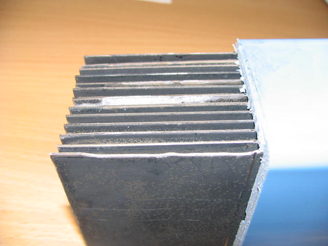
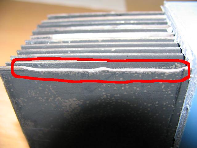
Here is corrosion caused by shunt current. You can see how the edge of the place was "chewed".
Edit: I should mention that this happened due to imperfection of the assembly. Error was made on the assembly line and overlooked during test's. In
bad cases you can loose significant part it titanium mass and cause structural damage. At the same time you 'dilute" titanium in solution
[Edited on 25-10-2008 by simple]

|
|
|
tentacles
Hazard to Others
  
Posts: 191
Registered: 11-11-2007
Member Is Offline
Mood: No Mood
|
|
I've heard of this happening in some patent or other - the biggest factors are electrode spacing (the closer together, the more likely it is to
happen) and anode voltage. It's very unlikely to happen at lower anode voltages, but I believe around 6.5V you start to overcome the electrical
insulation of the Ti oxide layer (of any exposed Ti, like edges). It shouldn't be a big deal if we keep the anode spacing reasonable.
Didn't someone have a paper or something that covered anode spacing / efficiency?
|
|
|
Swede
Hazard to Others
  
Posts: 491
Registered: 4-9-2008
Member Is Offline
Mood: No Mood
|
|
I'd think closer spacing would reduce the voltage needed for a given current. Reduced voltages are desireable, correct? The single MMO anode I had
up until recently, I have been running at 5.5 to 7.5 V which gave me anywhere between 40 and 60 amps. I've gone as low as 7% Cl- concentration, but
no lower. I haven't seen a hint of damage yet, but that doesn't mean there is none.
I'm thinking if we increase electrode surface area, and strap cross section, and find a spacing that will allow 60 to 80 amps at say 5V for chlorate,
then the electrode set will run relatively cool and have a long life. I'm suspecting most cases of damage result from an excess current density, a
low ion concentration, or a combination of both.
|
|
|
dann2
International Hazard
    
Posts: 1523
Registered: 31-1-2007
Member Is Offline
Mood: No Mood
|
|
Hello Folks,
@ Simple
Welcome to the never ending Chlorate/Perchlorate making + anode making discussions.
Are the anodes in the picture MMO (for Chlorate).
Do the cathodes go in between the anode sheets?
Could you 'repair' an anode (if you knew it was being eaten away by a shunt current problem) while it was still in the cell by shutting off the power
supply and then slowly applying an increasing voltage to the cell so that any parts of exposed bare Ti (no Ti Oxide) plate would get a chance to form
a protective Oxide coat.
Most cells run in the garage have quite a large spacing between anode and cathode (compared to industrial cells). Therefor I think (guess) that the
problem of shunt currents damaging Ti substrates in home cells will probably not occur.
The closer the electrodes the higher the shunt current risk as Tentacles said?
Also the higher the solution resistance the higher the shunt current risk?
@Swede
Closer spacing of electrodes will give a smaller voltage accross cell (for a given current) but as you decrease the spacing (as Simple said) the risk
of shunt current corrosion will increase. Industrial makers are obsessed with voltage accross the cells as this saves power. The home maker will not
worry about an extra volt or so accross their cells.
Will keeping all corners on anodes as rounded as possible also reduce the risk of shunt current erosion?
Are modern Perchlorte cells pH controlled?
Sorry about all the questions and thanks for the pict's.
Dann2
[Edited on 25-10-2008 by dann2]
|
|
|
Swede
Hazard to Others
  
Posts: 491
Registered: 4-9-2008
Member Is Offline
Mood: No Mood
|
|
Great!  Now we have "shunt current erosion" to worry about... as if there
weren't enough issues with this process. Now we have "shunt current erosion" to worry about... as if there
weren't enough issues with this process.
I think what a lot of this boils down to is too much power. Many of us (me included) are taking 2" X 5" mesh anodes and jamming 60+ amps through
them. If we either increase the size of our systems, especially electrode area, and/or decrease the current a bit, erosion, overheating, and other
problems will be minimized.
|
|
|
Splinky
Harmless

Posts: 19
Registered: 9-2-2008
Location: Elsewhere
Member Is Offline
Mood: No Mood
|
|
Wow, it's been a while since I've looked around on here...
I just set up my potassium chlorate cell with an MMO anode/cathode set from northstar pyro, I made a run to a hardware store and picked up a 40 lb bag
of KCl so I should be set for a while.
My setup is a simple two liter soda bottle with the top cut off and the anode/cathode suspended in the solution with a 6 amp 6 volt battery charger
power source. I didn't make any sort of venting apparatus aside from open windows, and in the NaCl test runs I have done I haven't experienced any Cl
problems aside from a faint smell for the first half hour or so. After that, all I get is a faint bleachy smell. Is there any problem with that, or
could it still be giving off harmful amounts of chlorine without me being able to smell it?
Swede- Your blog on APC is pretty interesting, it's nice to have some sort of running commentary from someone who is putting time into (per)chlorate
production. I haven't been able to even get onto the site from my home computer, but it's nice to know you post here too.
|
|
|
kclo4
National Hazard
   
Posts: 916
Registered: 11-12-2004
Location:
Member Is Offline
Mood: No Mood
|
|
Well, I'm sure its not good to be exposed to small amounts of atmospheric chlorine, so I guess it depends on how much you care? If you can't smell it,
I bet their is very little in the air. Just make sure most of the chlorine gets dissolved so you don't have to worry about it - plus, it will increase
your yield.
|
|
|
Splinky
Harmless

Posts: 19
Registered: 9-2-2008
Location: Elsewhere
Member Is Offline
Mood: No Mood
|
|
I just went out and checked, there is no smell and very little gas production at the anode. I guess that means it's mostly dissolving.
|
|
|
Xenoid
National Hazard
   
Posts: 775
Registered: 14-6-2007
Location: Springs Junction, New Zealand
Member Is Offline
Mood: Comfortably Numb
|
|
| Quote: | Originally posted by dann2
Are modern Perchlorte cells pH controlled?
|
@ Dann2 - is not 1960 "modern" enough for you! 
The Djvu version of the Perchlorates Monograph, you yourself posted here a while back has tables (pp 74 - 75) and discussion (pp 85 - 86) on pH
control. In general, slightly acid to neutral conditions are preferred, with pH 6.6 - 6.8 being used in commercial operations.
This is only for current efficiency reasons and is not a problem for amateurs using platinized Ti of PbO2 electrodes. Indeed, the stability field of
PbO2 is expanded at higher pH. From memory, my assorted perchlorate cells approached pH 12 after extended running. I guess this is why my various
baked MnO2 anodes performed very poorly in perchlorate (and less poorly in chlorate) cells. At high pH, MnO4- (permanganate) (recall Purple Haze) and
MnO4= (manganate) are the stable (aqueous) species. pH would have to be kept below about 4 for an MnO2 anode to remain stable. I am not sure if a pH
this low is feasible in a (per)chlorate cell. In a strongly acid solution an MnO2 anode would rapidly dissolve (Mn++) in the absence of the highly
oxidising conditions on the anode surface.
All this assumes I am interpreting the Pb and Mn Pourbaix diagrams correctly! 
|
|
|
dann2
International Hazard
    
Posts: 1523
Registered: 31-1-2007
Member Is Offline
Mood: No Mood
|
|
Hello Folks,
@Xenoid. That clears up the pH thing in Perk. cells.
When I operated a Perk. cell with a LD anode the pH went to 10.8. Lots of Lead was depositing on the cathode. Perhaps this would not have happened if
pH was kept at around 6 or 7.
@Splinky. If you are not controlling pH then there is no way Chlorine can escape from the cell after it has started to operate for an hour or so.
Regarding the shunt current problems (the new spanner in the works), I don't think it is a problem for us at all.
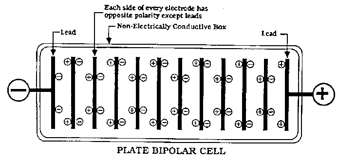
There are two types of cells used in Industry. Monopolar and Bipolar. The Bipolar cells use a row of electrodes 'in series' in the same cell. There
are no seperate anodes and cathodes as such except the two end electrodes which have the + and - connected to them. All other electrodes are an anode
on one side and a cathode on the other side (of the same MMO (or whatever) coated plate) with no actual electrical connection going to them! It is a
set up we will never be using. I won't anyways.
All our cells are Monopolar and therefor will be very unlikely to get effected with this problem.
The electrodes pictured by Simple are (I think) from Bipolar set up's.
(I think it would be near impossible for the actual anode or cathode to get effected by shunt currents in a Monopolar cell. Perhaps some metal used as
part of the cell construction might get eaten by a shunt current problem)
Bipolar cell pictured below.
Also the linked document explained it better than I can:
http://ifile.it/d342ftr
There is also a paper discussing the prediction of Shunt Currents in Bipolar cells in the References wanted in the Reference section. It is essential
bedtime reading. A absolute must for all garage chlorate making Guru's. 
Dann2
[Edited on 26-10-2008 by dann2]

|
|
|
simple
Harmless

Posts: 19
Registered: 25-7-2006
Location: AussieLand
Member Is Offline
Mood: No Mood
|
|
Dann2, thanks for welcome.
Pictured anodes are RuO based and electrode is designed to generate low concentrations of sodiumhypochlorite in NaCL solution. It is bipolar and
revere polarity assembly.
Main rule for shunt current it that resistance between any two oppositely charged and exposed parts of electrode should be significantly more that
between working surfaces of the electrodes.
Reading more in to this thread, i can also recommend keeping titanium conductors / assembly made of pretty high grade, say CP or Grade1. pH variations
will corrode low grade titanium alloy. If you check grade specs, you will find a lot of aluminum in the lower grades. This makes if fairly unstable.
|
|
|
Rosco Bodine
Banned
Posts: 6370
Registered: 29-9-2004
Member Is Offline
Mood: analytical
|
|
Coaxial electrodes are looking better all the time hmmmm?
|
|
|
| Pages:
1
..
3
4
5
6
7
..
48 |