| Pages:
1
2 |
woelen
Super Administrator
        
Posts: 8014
Registered: 20-8-2005
Location: Netherlands
Member Is Offline
Mood: interested
|
|
Most flybacks are not suitable. You need one without built-in rectifier. I do not do the rectification step from the web-page I linked to, I use the
AC-output. Glowing discharge tubes made entirely of glass without electrodes only is possible with high frequency AC.
I purchased a transformer with only a secondary winding (2400 turns) and then I can make my own primary of appr. 10 turns.
|
|
|
careysub
International Hazard
    
Posts: 1339
Registered: 4-8-2014
Location: Coastal Sage Scrub Biome
Member Is Offline
Mood: Lowest quantum state
|
|
Looking for a semi-OTS solution for lighting up the gas tubes in an element display, perhaps all at once (but not necessarily).
Analog HV electronics are not my forte, and I would rather not try to build a solution, and am not well equipped to evaluate offerings. Safety of any
solution especially concerns me, making me wary of trying to implement my own solution.
I received the industrial Tesla coil and it is very nice, 6 cm sparks! This is a form of AC I understand, so perhaps I could use this to energize
tubes with external electrodes by having one going to ground (and using suitably high breakdown wiring)? Still waiting on my gas tubes.
Current limiting an NST with a resistor looks like a non-starter since the output power is so high (200-300 watts).
Alternatively, this site has a lot of HV products of various kinds:
http://www.amazing1.com/hv-hf-power-supplies.html
http://www.amazing1.com/transformers-high-voltage-high-frequ...
but I am unable to tell if there is anything usable for the desired application. To the extent that they describe the output of most of their devices,
it seems to be DC. The have "easily disassembled" fly-back transformers, which sounds promising, presumably if they have rectifiers they can be
removed.
[Edited on 11-6-2016 by careysub]
|
|
|
woelen
Super Administrator
        
Posts: 8014
Registered: 20-8-2005
Location: Netherlands
Member Is Offline
Mood: interested
|
|
NSTs already are current limited by design. They are specified with open loop voltage and with short circuit current. The heavier the load, the lower
the voltage. This behavior is beneficial for gas discharge loads, because initially, when there is no current flowing, the lamps need a high voltage
to ignite, and once they ignite, their current tends to grow without limit, but the transformer limits the current to something less than the short
circuit current.
The site amazing1.com has quite some interesting power supplies. The PVM12 is an AC power supply with adjustable output frequency and adjustable
output voltage. It looks nice. For me it is too expensive though, because it also must be shipped to my country and I'll have to pay 6% taxes plus EUR
20 or so declaration fee.
The GRADRIV10 also looks like an AC output device.
|
|
|
Twospoons
International Hazard
    
Posts: 1324
Registered: 26-7-2004
Location: Middle Earth
Member Is Offline
Mood: A trace of hope...
|
|
The power sources used by ozone generators would probably work quite well.
http://www.aliexpress.com/af/ozone.html?ltype=wholesale&...
These all operate using a high voltage high frequency dielectric barrier discharge. Specs are a bit sparse though.
Helicopter: "helico" -> spiral, "pter" -> with wings
|
|
|
careysub
International Hazard
    
Posts: 1339
Registered: 4-8-2014
Location: Coastal Sage Scrub Biome
Member Is Offline
Mood: Lowest quantum state
|
|
This one:
http://www.amazing1.com/products/plasma-power-generator-7kv-...
for $40 might be right-sized for the element display, 7 KV at 10 mA.
A $40 voltage multiplier add-on is available to boost the output to 35 KV at 2 mA if needed (probably not).
Tubes to be driven: H, D, He, N, O, Ne, Ar, Kr, Xe; possibly Cl, Br and I. So up to 12 tubes.
|
|
|
j_sum1
Administrator
       
Posts: 6324
Registered: 4-10-2014
Location: At home
Member Is Offline
Mood: Most of the ducks are in a row
|
|
Quote: Originally posted by careysub  | This one:
http://www.amazing1.com/products/plasma-power-generator-7kv-...
for $40 might be right-sized for the element display, 7 KV at 10 mA.
A $40 voltage multiplier add-on is available to boost the output to 35 KV at 2 mA if needed (probably not).
Tubes to be driven: H, D, He, N, O, Ne, Ar, Kr, Xe; possibly Cl, Br and I. So up to 12 tubes. |
As far as i can tell, this one is similar at a better price.
http://www.ebay.com.au/itm/401122166917
If someone can confirm that it is likely to work then I will grab one or two. I am much more comfortable with buying something than attempting to
construct my own.
|
|
|
Twospoons
International Hazard
    
Posts: 1324
Registered: 26-7-2004
Location: Middle Earth
Member Is Offline
Mood: A trace of hope...
|
|
There's no indication if the output is DC or AC. From the description of the purpose (ignition) I'd guess its DC, from an internal diode multiplier,
which is not what you want.
[Edited on 15-6-2016 by Twospoons]
Helicopter: "helico" -> spiral, "pter" -> with wings
|
|
|
j_sum1
Administrator
       
Posts: 6324
Registered: 4-10-2014
Location: At home
Member Is Offline
Mood: Most of the ducks are in a row
|
|
Ah. Thanks for that compatriot.
|
|
|
woelen
Super Administrator
        
Posts: 8014
Registered: 20-8-2005
Location: Netherlands
Member Is Offline
Mood: interested
|
|
This is a pulse generator. It generates sparks, once per second or so. These sparks can be used to ignite something, e.g. gas in a burner. I myself
have such a thing, it produces 40 kV sparks with a 6 mJ energy content. It charges a small high voltage capacitor (7 to 8 pF) until a spark occurs.
|
|
|
careysub
International Hazard
    
Posts: 1339
Registered: 4-8-2014
Location: Coastal Sage Scrub Biome
Member Is Offline
Mood: Lowest quantum state
|
|
Results of testing my Chinese set of noble gas tubes plus hydrogen with commercial Tesla coil vacuum tester (an Electro-Technic Products BD-10), which
has a variable voltage from 20 to 50 KV at a frequency of 500 KHz and a maximum current of 0.1 mA.
I tested them by just touching the coil electrode to the tube, and by also grounding one end with an 8 foot length of 100 KV wire.
They all produced some visible glow in a well lit interior room, the neon was far and away the brightest, faint for hydrogen. In a fairly dark room
they all glowed quite visibly, though some much brighter than others.
Grounding one end while touching the electrode to the other produced the strongest, most even, display. But it was only modestly better than
ungrounded.
20 KV lit up the tubes nicely. 50 KV produced much stronger arcing, and a slight increase in output, but this voltage is excessive since arcing is an
undesirable effect.
I was able to clearly light up the four easiest tubes stacked side by side all at once (neon, krypton, xenon, and helium) with 20 KV.
Trying to transfer the current from the electrode to the gas tube over the 8 foot wire produced a feeble effect, only slightly enhanced by grounding
one end. This is more or less what I expected since a Tesla coil is an odd-ball AC source, without a regular neutral/ground line.
The xenon and krypton tubes produce brightly glowing conducting channels, not just a glow, unlike the others.
My conclusions.
A Tesla coil of 20 KV is fine for displaying an electrode-less glass gas tube by electrode contact, and even energize multiple tubes in physical
contact if the coil is strong enough. It cannot be used to light up a display of mounted tubes via wiring.
All of the gas tubes will put on a useful glow if mounted in a dark recess to maximize the effect.
My recommendation for powering a mounted display (to be tested, once I get the power supply) is a 15-20 KV high frequency AC supply, with grounding.
Since I got a good effect at 20 KV, I think it is safe to say that 15 KV will do well also.
0.1 mA is plenty of current for one tube (although the dimmer tubes might benefit from a higher current?). For a multitube display, lit all at once,
1-2 mA should be fine.
14 KV neon sign transformers are readily available, but put out 20 mA, which is about ten times more current than needed for this.
I think making a tube holder for each tube out of a copper wire coil on each end (which are the electrodes) is a good display design.
I think the MINIMAX40 (NEONX80), $27, and the MULTI50 voltage multiplier, $40, combination from the source below which together produce 20 KV at 1 mA
(25 to 35 KHz) is about right for this:
http://www.amazing1.com/hv-hf-power-supplies.html
I am going to order one of these and set up a display prototype.
[Edited on 19-6-2016 by careysub]
|
|
|
Dan Vizine
National Hazard
   
Posts: 628
Registered: 4-4-2014
Location: Tonawanda, New York
Member Is Offline
Mood: High Resistance
|
|
It seems this very interesting thread just kind of dried up. Anybody have any later results which might indicate the most cost effective power source
to illuminate gas tubes such as those sold by yaolihong2013 on eBay?
"All Your Children Are Poor Unfortunate Victims of Lies You Believe, a Plague Upon Your Ignorance that Keeps the Youth from the Truth They
Deserve"...F. Zappa
|
|
|
j_sum1
Administrator
       
Posts: 6324
Registered: 4-10-2014
Location: At home
Member Is Offline
Mood: Most of the ducks are in a row
|
|
Nope. Not from me. This is one of my many shelved projects. But in the interim I have collected nearly a full set of inert gases in nice ampoules
from yaolihong2013. Just Xe to go.
|
|
|
Dan Vizine
National Hazard
   
Posts: 628
Registered: 4-4-2014
Location: Tonawanda, New York
Member Is Offline
Mood: High Resistance
|
|
I also purchased the set except argon. A 2.5 kV transformer with wires wrapped around the tube did nothing, as expected.
Too bad about the lack of results, I was hoping to ride on your and the other's coattails!
[Edited on 2/21/2017 by Dan Vizine]
"All Your Children Are Poor Unfortunate Victims of Lies You Believe, a Plague Upon Your Ignorance that Keeps the Youth from the Truth They
Deserve"...F. Zappa
|
|
|
woelen
Super Administrator
        
Posts: 8014
Registered: 20-8-2005
Location: Netherlands
Member Is Offline
Mood: interested
|
|
No, 2.5 kV is too low for such thick-walled ampoules. You need at least 10 kV or so for decent light output.
|
|
|
Dan Vizine
National Hazard
   
Posts: 628
Registered: 4-4-2014
Location: Tonawanda, New York
Member Is Offline
Mood: High Resistance
|
|
With 10 kV @ 50 or 60 Hz (a reasonable neon sign transformer), is it your experience that a coil at top and another wrapped around the other end will
give a reasonable glow?
The 2.5 kV transformer (from a junked hplc to power the UV detector) makes a little neon lamp glow like a red LED! No surprise, this little negative
resistance trinket heats up fast.
[Edited on 2/22/2017 by Dan Vizine]
"All Your Children Are Poor Unfortunate Victims of Lies You Believe, a Plague Upon Your Ignorance that Keeps the Youth from the Truth They
Deserve"...F. Zappa
|
|
|
wg48
National Hazard
   
Posts: 821
Registered: 21-11-2015
Member Is Offline
Mood: No Mood
|
|
Wrapping wire round the end of the ampoules creates a capacitance to the gas of a round 20pF and there is two of them in series. At 50/60Hz that is
an impedance of about 320 x 10^6 ohms at 10kV that will produce a current of only about 35uA which will not be very bright.
To get more current into the gas and hence brighter you need a much higher frequency 20kHz and up to MHz.
A mains HV transformer is not the brightest option LOL
You need something like this
http://www.ebay.co.uk/itm/DC-High-Voltage-Generator-Inverter...
and here is a 500kV one (an example gross inaccurcy but it would mean you could claim your money back)
http://www.ebay.co.uk/itm/DC-6v-12V-to-500Kv-High-Voltage-Co...
[Edited on 23-2-2017 by wg48]
[Edited on 23-2-2017 by wg48]
|
|
|
Dan Vizine
National Hazard
   
Posts: 628
Registered: 4-4-2014
Location: Tonawanda, New York
Member Is Offline
Mood: High Resistance
|
|
Thanks wg48,
I had absorbed just enough of what was said earlier to be hesitant to think 60 Hz would be good enough.
Dan
"All Your Children Are Poor Unfortunate Victims of Lies You Believe, a Plague Upon Your Ignorance that Keeps the Youth from the Truth They
Deserve"...F. Zappa
|
|
|
wg48
National Hazard
   
Posts: 821
Registered: 21-11-2015
Member Is Offline
Mood: No Mood
|
|
Dan:
I should also add that you need a higher voltage (about X2) to start the gas conducting (breakdown) than to maintain it glowing. The actual voltage is
dependent on the gas, its pressure and the distance between the electrodes. You may not have the optimum gas pressure. From memory it’s a round a
few torr of pressure.
There are things you can do that will increase the chances of getting the glow going and making it brighter. Increase the capacitance of the
connections, say by silver plating the tube ends to increase the surface area. Perhaps put a conductive strip on each side of the tube to decrease the
separation. Of cause of a white or reflective background may make it look bright or a black background if the ambient light level is higher than the
glow. I don’t know the output impedance of your mains transformer but its probably much lower than the impedance of the tube so the tubes should be
connected in parallel.
You could also use your 10kV transformer to build a small Tesla coil. That will make your tube/s glow.
|
|
|
Dan Vizine
National Hazard
   
Posts: 628
Registered: 4-4-2014
Location: Tonawanda, New York
Member Is Offline
Mood: High Resistance
|
|
Wg48,
Thanks.
I don't actually see anyone who just outright states "I have yaolihong2013's sample tubes and here's how I made them glow". Maybe I'm reading too much
into that, but I'm not as sanguine about the prospects of success as I once was.
"All Your Children Are Poor Unfortunate Victims of Lies You Believe, a Plague Upon Your Ignorance that Keeps the Youth from the Truth They
Deserve"...F. Zappa
|
|
|
j_sum1
Administrator
       
Posts: 6324
Registered: 4-10-2014
Location: At home
Member Is Offline
Mood: Most of the ducks are in a row
|
|
Here's one.
https://www.youtube.com/watch?v=SD07uTBlmJk
But few details given.
|
|
|
NeonPulse
Hazard to Others
  
Posts: 417
Registered: 29-6-2013
Location: The other end of the internet.
Member Is Offline
Mood: Isolated from Reality! For Real this time....
|
|
O.K here's how i did it...
Quote: Originally posted by Dan Vizine  | Wg48,
Thanks.
I don't actually see anyone who just outright states "I have yaolihong2013's sample tubes and here's how I made them glow". Maybe I'm reading too much
into that, but I'm not as sanguine about the prospects of success as I once was. |
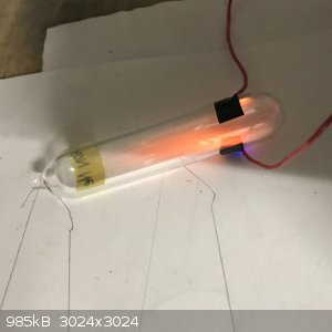
I actually have the gas tubes from this seller and actually got the neon one and argon ones to glow. the neon one obviously glowed very nicely orange
as expected but the argon one is the only other one i actually got a result from.
I didn't think my experiment would even work but was pleased when it did.
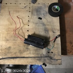
The power for this was one of these cheap discharge capacitors:
http://www.ebay.com.au/itm/ultra-high-1000KV-High-Voltage-Pu...
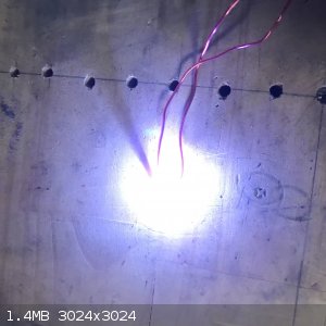
i attached a 18650 battery holder and a momentary power switch to it and when it is powered up it fires quite loudly depending on the distance between
the end wires.
This is what i used to make the Neon Pulse..... since keeping it on for too long would probably fry the capacitor i had to make it pulse instead.
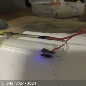
I simply attached the end contact wires to either side of the Neon gas tube and pressed the button. the brightness of the glowing was dependent on
where the wires were placed on the tube but offsetting them either side gave the best results.
I did try with the Oxygen, helium and krypton tubes with a barely perceptible glow coming from the helium tube. the best results were the Ne and Ar
tubes.
   
|
|
|
j_sum1
Administrator
       
Posts: 6324
Registered: 4-10-2014
Location: At home
Member Is Offline
Mood: Most of the ducks are in a row
|
|
Thanks for that NP.
I tried the same procedure with a 400kV unit without success. Somehow I missed the 1000kV ones. Just how grunty do these things get? I haven't seen
anything bigger than 1000kV in my searches. It would be nice to have them glow along the entire length. It would be nice to get the other gases to
gow. And it would be really good to be able to leave them switched on for a while.
|
|
|
| Pages:
1
2 |