jock88
National Hazard
   
Posts: 505
Registered: 13-12-2012
Member Is Offline
Mood: No Mood
|
|
Variable resistors symbol
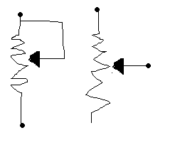
Variable resistors are usually shown as on the left. Why is that.
The symbol on the left is the same and a little less confusing.

|
|
|
aga
Forum Drunkard
    
Posts: 7030
Registered: 25-3-2014
Member Is Offline
|
|
The one one the Left is a potentiometer wired so that it becomes a variable resistor.
Twist the shaft and the Resistance changes between the top and the bottom blobs.
The one on the right is a potentiometer.
Twist the shaft any way you want, and the resistance between the top and bottom stays the same.
The resistance between the middle bit and either end will change as you twist the shaft.
[Edited on 27-5-2015 by aga]
|
|
|
Sulaiman
International Hazard
    
Posts: 3696
Registered: 8-2-2015
Location: 3rd rock from the sun
Member Is Offline
|
|
The drawing on the left is a variable resistor,
on the right is a potentiometer http://en.wikipedia.org/wiki/Potentiometer
Between one end of a potentiometer and the wiper IS a variable resistance,
By joining the wiper to one end of the potentiometer it is still the same variable resistance, but if the wiper briefly makes poor contact with the
resistance element then the resistance will 'jump' to the maximum resistance rather than to infinity / open circuit.
|
|
|
aga
Forum Drunkard
    
Posts: 7030
Registered: 25-3-2014
Member Is Offline
|
|
Potentiometers are used where you want to control how much juice goes out of the middle bit, compared to what goes in at the top, e.g. Volume Control.
It's very much a potential divider with an easy way to vary the values of R1 & R2.
http://en.wikipedia.org/wiki/Voltage_divider
[Edited on 27-5-2015 by aga]
|
|
|