len1
National Hazard
   
Posts: 595
Registered: 1-3-2007
Member Is Offline
Mood: NZ 1 (goal) - Italy 1 (dive)
|
|
A lab 40V 250W power supply
This post is for someone who wishes to develop a 40V 200W lab power supply from a standard PC XT supply, which are surplus now. We thought maybe some
others might benefit from this hence Im posting this in public. Please only contribute constructively.
The pictures Im posting is from a problem where the supply was modified to give 700V for a valve RF amp. The 40V amp is in a lot of ways simpler.
Rather than posting all the information, I shall do it step by step, less work for me, and less confusion for everyone. The idea is at the end to
have the supply as per specifications.
Before making modifications one needs to know something about how it works
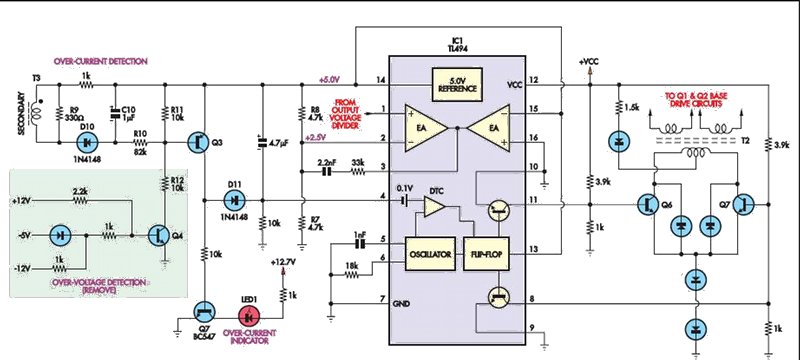
The picture below shows the schematic of the most common version of the driver side of the supply (without the push-pull output stage). Heres a
description.
The voltsper-turn ratio used in the secondary winding of a standard PC ferrite-cored transformer (operating in step-down mode) is about one turn per
volt output. Typical control circuitry based on a TL494 PWM controller is shown. There is quite a bit of variation in the control circuitry between
different manufacturers, so some circuits might differ somewhat. This is especially true if the over-voltage and over-current protection in your
supply is based on the LM339 comparator rather than on discrete transistors, as shown. Fortunately, there are few modifications to this part of the
circuit.
Operation is quite straightforward. The 240VAC mains is first rectified and then filtered by a capacitive divider to provide two supplies at ±170V
DC. This is switched alternately through the ferrite transformer by power transistors Q1 and Q2. A 1μF capacitor connected in series with the
transformer primary limits the current by forming an 8Ω load with the inductor. This provides some protection in case of a shorted secondary,
which effectively occurs at startup
before C1 & C2 are charged as well as during fault conditions. Transformer T3 is used to sense the magnitude of the primary current for
over-current
protection.
An important parameter in the design of the power sections of the circuit is the choice of the secondary voltage to output voltage differential. This
is needed to provide headroom to compensate for a drop in the secondary voltage with increased power output, the difference being made up by the by
duty cycle variation controlled by the TL494.
Secondary voltage drop has several sources: ohmic losses in inductor coils, non-linearity of the cores, 100Hz ripple due to discharge of mains storage
capacitors C6 & C7 and voltage drop across C8 which is charged and discharged every switching cycle. The latter two effects contribute to a
primary voltage ripple of 22V and 9V peak-topeak respectively at full output power, which manifests as a ripple across the secondary.
Output voltage regulation is achieved by varying the duty cycle so that the voltage applied to the TL494’s non-inverting amplifier input (pin 1)
equals the voltage on the inverting input (pin 2). In this case, 2.5V is applied to pin 2 via resistive divider R7 & R8. Hence, if R6=4.7kΩ,
then R3 +
R4 + R5 should equal 1311kΩ for 700V output, or 747kΩ for 400V. This secondary also supplies power to the TL494 via D7 & C5, as in the
original circuit.
How to one be sure that a self-made transformer will not saturate? The transformer is designed to deliver 250W power at near maximum duty, from a 170V
supply - thats a current of about 0.7A. To a first approximation the ferrite core is chosen so that it is capable of storing the entire energy
delivered to the load in one half period. The current is not quite constant, so one can be sure the core will not saturate up to about 1A
How to estimate voltages on switching transistors when transformers inductance comes into play? Provided the parasitic snubbing RC combination that
you can see across the primary is working, spice simulations and measurements show that the push-pull transistors impose a voltage of +/- 170V across
the primary alternatively - there is no voltage voltage. This can only arise between switching of the transistors.
[Edited on 8-15-2008 by Polverone]

|
|
|
len1
National Hazard
   
Posts: 595
Registered: 1-3-2007
Member Is Offline
Mood: NZ 1 (goal) - Italy 1 (dive)
|
|
The 494 is designed to control duty, and hence voltage, to keep voltages on pins 1 and 2 equal.
As a first step measure the voltages at pins 14 and 1 of the 494. Are they 5 and 2.5V respectively?
What rating are the smoothing caps across the 5V line and 12V line? 10V and 16V? if so we can continue.
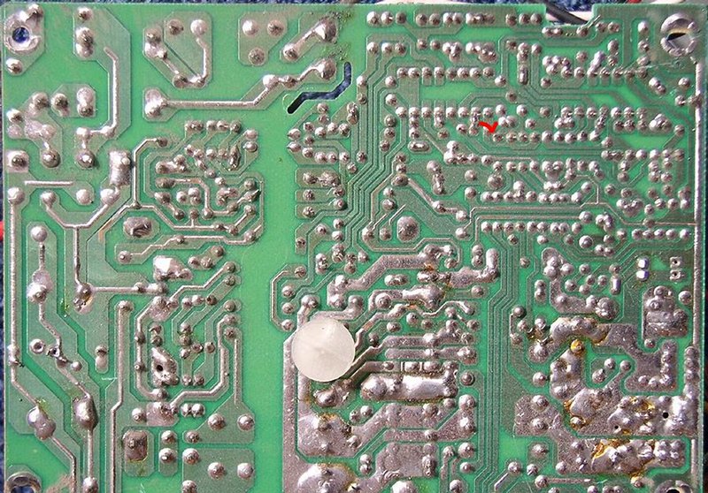
Put a 10W 3.3 ohm resistor across the 5V line. Break the track at pin 1 near the red line below, taking out the resistor. Solder a wire from the
tracking pin of a 1k pot here. Solder one end of the pot thru a 2.2kohm resistor to earth, the other end thru 2.2 kohm to the 5V line. By turning
the pot you should be able to vary the output voltage from 6.1V to 4.2V. If not, this is probably due to overV protection (shaded in diagram) which
will have to be removed in next part
end of part 1
Good idea to wear glasses when turning on switching supplies
[Edited on 15-8-2008 by len1]
[Edited on 8-15-2008 by Polverone]

|
|
|
12AX7
Post Harlot
    
Posts: 4803
Registered: 8-3-2005
Location: oscillating
Member Is Offline
Mood: informative
|
|
Those images are too wide.
| Quote: | | To a first approximation the ferrite core is chosen so that it is capable of storing the entire energy delivered to the load in one half period.
|
Not to a first approximation, in fact not at all. This is a forward converter, not flyback. The core must provide more than enough inductance that
it does not consume excessive drive current and does not saturate during a cycle. Nothing more, and it has no role in transferring power to the
secondary, which happens instantaneously.
As a forward converter, any load must have a choke input filter, which levels out the PWM from the rectifier. For a new voltage output, you will have
to wind a new one in addition to the winding on the transformer itself. It's not clear how you derived the turns ratio, but keep in mind it is
deceptively low: let's say you design your supply to operate at a typical 67% duty cycle (which is 33% for each output transistor and each output on
the TL494). This puts +/-160V pulses at 33% duty cycle (each) on the primary. If this waveform were rectified, you would recover 160V pulses at 67%
duty, or an average 107V. To obtain 5V, you need a turns ratio of 107/5 or about 21:1 (plus losses).
Another typical circuit (open loop, without protection hardware) looks like this:

Since I chose MOSFETs, I had to suppress the flyback pulse with an inductive method; this is probably not necessary with BJTs. The supply is from
120V + FWB, providing +/-80V to the inverter, half of a typical supply's rails (which are obtained with a voltage doubler (at 120V) or FWB (from
240V), hence the turns ratio is unusually low. The transformer was wound on an average 200W AT power supply transformer core, ungapped.
Tim
|
|
|
len1
National Hazard
   
Posts: 595
Registered: 1-3-2007
Member Is Offline
Mood: NZ 1 (goal) - Italy 1 (dive)
|
|
| Quote: | | Not to a first approximation, in fact not at all. This is a forward converter, not flyback. The core must provide more than enough inductance that it
does not consume excessive drive current and does not saturate during a cycle. Nothing more, and it has no role in transferring power to the
secondary, which happens instantaneously. |
Tim youre continuing to post this rubbish, despite me telling you its not correct. Theres plenty of books on electromagnetics you can learn this from
but you deliberately carry on. This is the trouble of this medium one idiot can ruin it for everyone. Im trying to help people here. Go away.
|
|
|
len1
National Hazard
   
Posts: 595
Registered: 1-3-2007
Member Is Offline
Mood: NZ 1 (goal) - Italy 1 (dive)
|
|
Apparently there are some problems with attempts to measure voltage on pin 1 of the 494, with the supply becoming unstable (fan going crazy,
transformer starting to buzz, PS shutting down).
I have repeteated today measurements on my supplies (I have about 10) and unfortunately couldnt reproduce the problem on a single one of them. They
all faithfully read 2.49V at pins 1 and 2 with the voltage absolutely stable.
My suggestion is measure the resistance at this point to ground (with supply off). All my supplies read about 2.8kOhm. Perhaps there are ones with a
much higher impedance at this point, which means high noise sensitivity at this point. The resistor at pin 1 in photo appears 100kOhm, but there are
others in parallel there too.
If the resistance here is above about 100kOhm, this part has to be skipped, let me know. Else solder a 1Mohm resistor with cropped leads directly to
pin 1. The other lead solder through a 0.1uF capacitor, with as short leads as possible to the earth at pin 7. The junction forms a test point. You
can measure voltage there across the capacitor. If the supply still reacts solder another 1MOhm resistor with cropped (1cm) leads to the test point
and measure voltage by touching it with voltmeter probe. The supply shouldnt react any more unless something is wrong with it or the voltmeter.
To find the internal impedance of the voltmeter use it to measure the voltage from a low resistance source, say battery, directly. Say this is V0.
Now measure it through a 1Mohm resistor, say its V1.
Impedance of voltmeter = V1/(V0-V1) MOhm.
The relation of measured voltage through 1MOhm resistor to actual is then
Vactual = Vmeasured * V0/V1
To make the potentiometer work try this.
Disconnect all from pin 1 and cut track. Solder a 2.2kOhm resistor with 1 cm leads between pin 1 and pin 7 - carefully so as not to short anything.
Solder the wire from a 500 ohm potentiometer to pin 1. Solder the other potentiometer wire to a 1.8k resistor and that to the 5V supply. Set the
potentimeter to 400ohm ohm. Turn on the PS. You should get 5V as before. Now vary the 500 ohm resistor, and you should be able to get the voltage
to vary in the ratio 4.5/4, i.e. Vmax/Vmin = 1.13
Once weve got a result for this we can proceed.
[Edited on 16-8-2008 by len1]
|
|
|
len2
Harmless

Posts: 32
Registered: 13-9-2008
Member Is Offline
Mood: No Mood
|
|
Sorry for long absence.
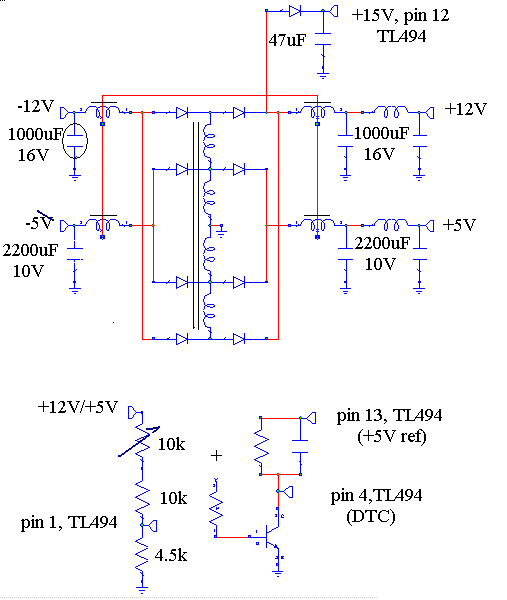
The next step in the development is the following modification of the PCSU supply which I have made and delivers 200W overall power, with the supply
variable in the range 3 - 30V.
I have kept modifications to a minimum, so at this stage the large variability is achieved by a combination of potentiometer variation, which varies
the 12V line as 8-15V to earth and 16-30V to the negative 12V line. The 5V line varies as 3.6-6.6V. The next stage if people are interested is to
introduce automatic switching and metering.
The changes entail removing the low power switching diodes from the -12V line and replacing with the high power bridge from the 12V line on another
PSU. Most of the PSU are of a type where the -12V line is filtered through the toroid. Unfiltered -12V lines cant be used since voltage regulation
is by means of an LC filter and variable duty cycle. Peak voltage is always the same, hence peak detection will give no voltage alteration if such
smoothing is used.
Note exactly this type of rectification provides power to the TL494, which hence doesnt vary with the potentiometer.
All components leading to pin1 of TL494 need be removed, and ones shown inserted. Pin 4 must be also arranged as shown, its voltage for proper
operation is close to ground.
Questions welcome

|
|
|
chromium
Hazard to Others
  
Posts: 284
Registered: 27-6-2005
Member Is Offline
Mood: reactive
|
|
Its great you are back again! I have followed your sugestions so far. As you know from U2U i disconnected everything from pin1 and connected
potentiometer with two resistors. So i was able to change voltage at 5V line from 4.19V to 6.09V.
Now i checked connections from main transformer secundary on my PSU and indeed its essentially as on drawing in your last post. My secundary has
aditional outputs for 3.3V which are connected with their own schottky diodes and own winding on filtering coil.
At time i did not replace low power diodes yet although i located them on PCB and can too it anytime. My question is about circuit for TL494 pin4.
What values are expected for resistors and capacitor and where to connect base resistor? I suppose transistor can be any common low power npn like
2N2222 or BC548? Also where to connect input of voltage divider for pin1?
When all think alike, then no one is thinking. - Walter Lippmann
|
|
|
len2
Harmless

Posts: 32
Registered: 13-9-2008
Member Is Offline
Mood: No Mood
|
|
Sorry I couldnt reply earlier. The resistor at pin 4 going to positive is about 4.7k, the capacitor about 10uF - they should alreadt be present in
the original circuit. Most circuits also have the transistor already there - it can indeed by bc548 or 2n2222 as you say.
The top of the resistive divider is connected to the rectified smoothed 12V output. The rectifiers for the negative line need to be heavy duty -
either the discrete diodes used as rectifiers in the +12V part of the supply, or the bridge
----|>------<|-----
paralleled as
----|>-----<|-------
| |
----------------------
for each diode
Len
|
|
|
jarynth
Hazard to Self
 
Posts: 76
Registered: 12-8-2008
Member Is Offline
Mood: No Mood
|
|
Interesting thread! Recently my interest in laboratory power supplies from computer ones started. A few comments on your scheme:
1) Can't you just save the power transformer and use it as-is without any kind of driving circuit (only a rectifier)? Do you have the self-inductance
data? Would it need some current-limiting? What's the secondary to primary ratio in your explicit case?
2) Why don't we stack a few power supplies in series? Even without the slightest understanding of the inner workings of such 'black boxes', you can
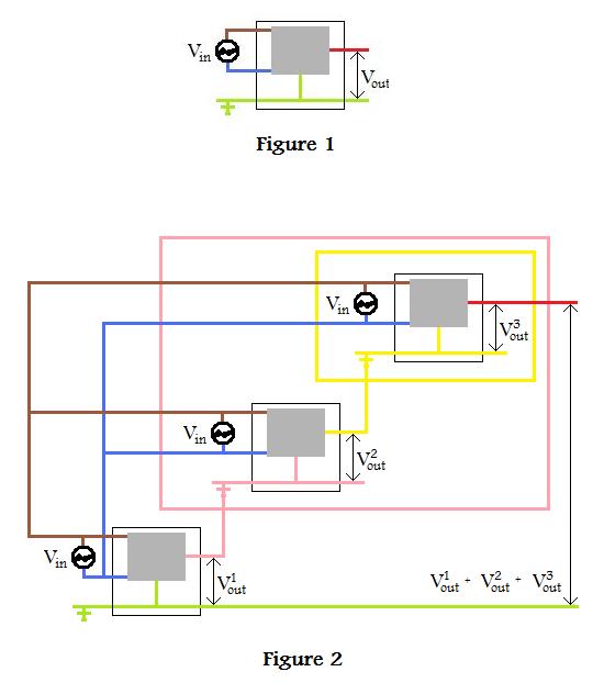
identify same-voltage output leads and bundle them to get the most current. For simplicity, I assumed you only have one possible (positive) output
voltage: (Figure 1)
This voltage is powerful, reliable, current-limited, overload-protected etc. I'd rather not mess with the circuitry just to see my PS fry because I
removed some sort of protection.
Now, to connect to PSs in series is kinda like stacking batteries, the only problem is we don't know which leads coming out of the PSs are
independent. But one thing is for sure: the GROUND will always be independent of the live output. Simply split up the mains cable of the right PS and
stick the GROUND wire into the secondary of the left PS. Iterate. Figure 2
Voltage regulation:
- for 1 PS, we can choose between +5V, +12V
- for 2 PSs, the combinations are +10V, +17V, +24V
- for 3 PSs, we can choose among +15V, +22V, +27V, +36V
Not to mention the fact that the available power gets added: eg using 3x250W ATX PSs for $10 each you'd get 50A at +15V and 20.8A at 36V. Warning: the
maximum current is limited by the 'weakest' element, ie max 20.8A in this example for +22V and up.
Parallel connections are even more straighforward, and will afford currents up to 150A at +5V in this example, at a cost of only $30. Overall, having
single PSs with bundled-up leads turns out very versatile. I'm going to try this with a few 600W 'elements'. 
An elegant touch would be to build a switch panel to toggle the connections from series to parallel and to change each voltage at the mere flip of a
switch. You'd get something like a commercial laboratory PS, only the possible voltages have a discrete range of values. But hey, I never liked those
tricky potentiometers anyway. 
[Edited on 3-10-2008 by jarynth]

|
|
|
dann2
International Hazard
    
Posts: 1523
Registered: 31-1-2007
Member Is Offline
Mood: No Mood
|
|
Read up on computer PSU's
Keep up the good work Len1.
Sorry Jarynth, but I am going to have to give your post the old 
Hope I'm not barred off the Interweb (not to speak of SM.ORG) for that. 
Dann2
|
|
|
jarynth
Hazard to Self
 
Posts: 76
Registered: 12-8-2008
Member Is Offline
Mood: No Mood
|
|
| Quote: | Originally posted by dann2
Sorry Jarynth, but I am going to have to give your post the old  |
LOL, can you elaborate on that a little bit? Of course it's a completely different approach, probably inelegant to the electronic geek in everyone of
us, but does it warrant the rolleyes? You have to challenge the mainsream sometimes. I am not necessarily looking for applause; if I was, I'd be
talking about poor endangered panda bears in front of a greenpeace symposium. 
|
|
|
dann2
International Hazard
    
Posts: 1523
Registered: 31-1-2007
Member Is Offline
Mood: No Mood
|
|
These supplys cannot be connected as shown. They will malfunction or worse.
They are switch mode supplies and do not contain a power transformer as such.
It may be possible to connect them in parallel using diodes to isolate each supply from the next (you may not need diodes as the supplies may have
suitable diodies internally). Current balance would be a problem. You could use resistors to help balance current but it's a crude solution.
I will have to humbly withdraw the rolleyes.
See Tumadre's post of 8 - 4- 2007 here:
http://www.sciencemadness.org/talk/viewthread.php?tid=3885&a...
for some info. on connecting is series + some more posts after, for to connect in series.
Dann2
|
|
|
chief
National Hazard
   
Posts: 630
Registered: 19-7-2007
Member Is Offline
Mood: No Mood
|
|
What about the new "inverter-type" welding-transformers ? I saw some for 100 EUR: 10-80 A current capability, at the welding-voltages ! (displace
welding-transformers from now on ...)
Those should be technologically about the same as the PC-power-supplys, only bigger ? ..
Only that they maight control the current instead of the voltage, but then: Having 5 electrolytic cells in series, at 50 A each, means 250 A too !
[Edited on 5-10-2008 by chief]
|
|
|
12AX7
Post Harlot
    
Posts: 4803
Registered: 8-3-2005
Location: oscillating
Member Is Offline
Mood: informative
|
|
Probably not 100% duty cycle at such currents, much as the old iron buzzboxes are rated.
Tim
|
|
|