| Pages:
1
..
30
31
32 |
Dr.Bob
International Hazard

Posts: 2821
Registered: 26-1-2011
Location: USA - NC
Member Is Offline
Mood: Mildly disgruntled scientist
|
|
I also just took new photos of my remaining condensers. I got some for some trades, some I just dug out, and others I have had. I also have a few
Wests I have in some 24/40 kits that I am putting together.
I have a bunch of Allihans for $20 each for the unlabelled ones, $25 for the LG longer one. The Fredrichs both have issues, one is new but the inner
tube is broken, easy enough to fix, the other one is missing the inner tube and adapter, they would be $20 each. The Vigreauxs are $20 each, and I
have two small liebigs for $20 each. The coil condenser are $25 for the Chemglass coils, and the like new Synthware reflux coil one.
  
|
|
|
Dr.Bob
International Hazard
Posts: 2821
Registered: 26-1-2011
Location: USA - NC
Member Is Offline
Mood: Mildly disgruntled scientist
|
|
I also has someone ask me about stirrers, I have three working ones. I don't have any heating stirplates right now, but trying to get some fixed.
The Corning PC-410 is the newest, the dial is damaged, but otherwise it is great, I would ask $60. The Corning PC-310 is older, $50, and the VWR 310
is $50.
  
|
|
|
Dr.Bob
International Hazard
Posts: 2821
Registered: 26-1-2011
Location: USA - NC
Member Is Offline
Mood: Mildly disgruntled scientist
|
|
Here are two boxes of books I would like to give away for postage only. First come, first serve, but I will be out town soon for a little while, so
I may have to arrange shipping then, but books will be allocated basedd on the first to u2u or email me. Cost would be ~$5 for one or two books,
~$10 for a medium sized box, and about $15-20 for a large box, as media mail rate is low for large boxes.
These have been claimed so far:
CRC Handbook
Protective groups in organic synthesis
The excitement and fascination of science
Effective writing for Engineers, Managers, Scientists
 
[Edited on 3-2-2025 by Dr.Bob]
|
|
|
Dr.Bob
International Hazard
Posts: 2821
Registered: 26-1-2011
Location: USA - NC
Member Is Offline
Mood: Mildly disgruntled scientist
|
|
First, a good chunk of the books are claimed for now. I will be out of town for a while, so any other requests I will handle once I get back, as
well as any interest for glassware. Once I get back I will catch up on any new requests, as well as post more photos of books to select from. Hope
everyone stays well.
|
|
|
SuperOxide
National Hazard
Posts: 539
Registered: 24-7-2019
Location: Devils Anus
Member Is Offline
|
|
@Dr.Bob, looking at the condensers in this reply:
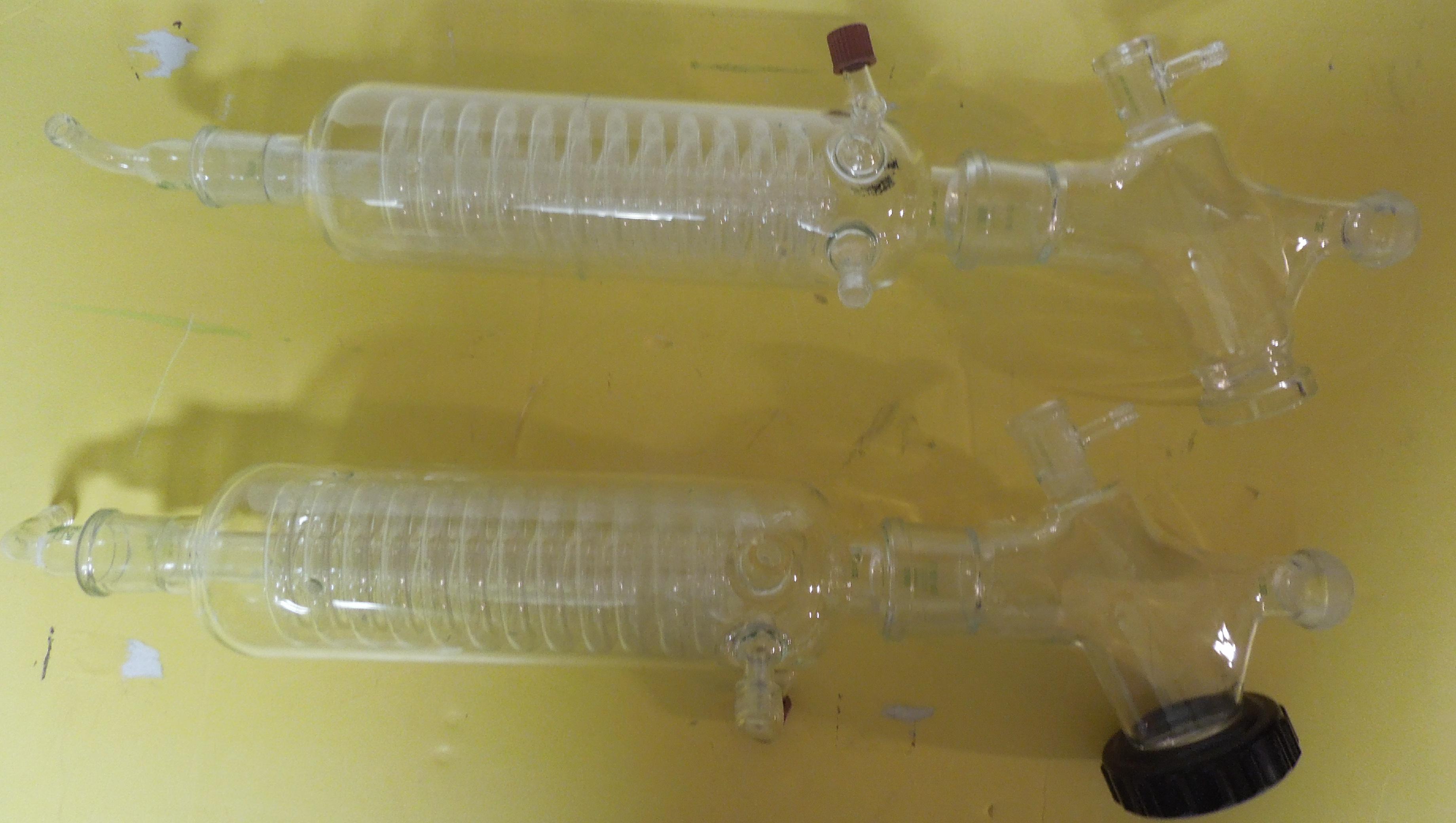
- Are either of the condensers still in stock?
- Do either of the condensers include the feedstock valve like what you posted here?
- On both of those condensers I see a red fastner nut thing, do you know what that's for? Im wondering if it could be used for a temperature
probe for an R-205 rotovap.
|
|
|
Dr.Bob
International Hazard
Posts: 2821
Registered: 26-1-2011
Location: USA - NC
Member Is Offline
Mood: Mildly disgruntled scientist
|
|
I think I have sold those, but might have a similar one left, I will check now that I am back. I do have lots of simple water condensers left, that
are one piece. The red nut is where you can also hook up the vacuum, or put in a vacuum meter. I might have one which can hold a temp probe, but
they are not very accurate in a vacuum, so I rarely use that. But I will see what I have shortly.
For everyone else with questions, I will try to get back to you soon now that I am home, but it may take a few days to get caught up. Had a greta
time away from work.
|
|
|
Dr.Bob
International Hazard
Posts: 2821
Registered: 26-1-2011
Location: USA - NC
Member Is Offline
Mood: Mildly disgruntled scientist
|
|
Here is another list of books to give away, I have a few people that asked before but were too late, they get first dibs on these, but any other
requests will be first come first serve.

|
|
|
Dr.Bob
International Hazard
Posts: 2821
Registered: 26-1-2011
Location: USA - NC
Member Is Offline
Mood: Mildly disgruntled scientist
|
|
Superoxide,
I don't have any water condenders like shown above, but I do have several of the simpler ones like shown below. They can also be set to allow adding
more material while in use. The red nut is a cap that seals the vacuum inlet, but can be replaced by an inlet adapter or other 5mm tube. The first
two has threaded hose adapters, the second two have standard hose barbs for the water and vaccuum lines. I can provide the stopcocks, threaded
connector and other parts as well. These are listed on Ebay for up to $200, but I would sell them here for about $150, plus shipping, depending on
what other parts you need.
 
 
[Edited on 26-2-2025 by Dr.Bob]
|
|
|
Dr.Bob
International Hazard
Posts: 2821
Registered: 26-1-2011
Location: USA - NC
Member Is Offline
Mood: Mildly disgruntled scientist
|
|
Here are a few more flasks I just unpacked. These are mostly 24/40 joints.
A - 24/40 2L evaporating flask - Chemglass - $30
B - 24/40 2L RBF with 1 neck - Pyrex - $25
C - 24/40 1L RBF with 3 necks - Pyrex - $25
D - 29/42 evaporating flask - ? - $20
E - 24/40 1L RBF with 1 neck - Prism (local Co) - $15
F - 24/40 1L RBF with 1 neck - Chemglass - $15
G - 24/40 2L RBF with 1 neck - Kontes - $25 (lost photo, working on it.)


[Edited on 2-3-2025 by Dr.Bob]
|
|
|
Dr.Bob
International Hazard
Posts: 2821
Registered: 26-1-2011
Location: USA - NC
Member Is Offline
Mood: Mildly disgruntled scientist
|
|
I have yet a few more big things to sell. First off is a large rotovap, which I do not know much about. It likely worked, but I don't know for
sure, and don't have the space or time to test it. The good news is that means I just want to sell it for parts or repair, and you can have it for a
fraction of its original cost. Shipping would likely be more than the cost, so if you are near NC it would be easier to arrange a low cost way to
pick up or deleivery it. But I can try to arrange shipping as well, for enough money. Make me an offer or let me know if you are interested.
   
|
|
|
Dr.Bob
International Hazard
Posts: 2821
Registered: 26-1-2011
Location: USA - NC
Member Is Offline
Mood: Mildly disgruntled scientist
|
|
Next up is a chiller/heater circulator system. From USA Lab, a UHC-50/40 system that sells new for $10K. It is fairly new and was working
recently. It was used with a large jacketed reactor. This we are looking for an offer of $3000 to $3500, plus shipping or pickup. Also available,
a huge vacuum/pressure pump from GAST, a 4565-V150, a 6HP motor, runs on 208V 3 phase. A big momma. And last I have a portable clean room, 8 x 8 x
8 feet, with Hepa filters, fans, lights, and more.
See https://www.ebay.com/itm/125829179339
See https://www.ebay.com/itm/365485028774
 
 
[Edited on 18-4-2025 by Dr.Bob]

|
|
|
| Pages:
1
..
30
31
32 |