This article is part of a series of
Illustrated Key Syntheses in Chemistry which I intend to post, with the purposes and guidelines outlined in the thread of the same name in the General
Chemistry section.<br> I shall attampt to ensure that the first post in all syntheses contains all the relevant information. If something
needs to be added later on, due to comments further down the thread for instance, I shall edit the first post.
Aim
It is the aim here to present an illustrated demonstration of a method for the amateur chemist to produce useful quantities of sodium metal for
laboratory use. The method relies on electrolysis of molten NaOH, a process patented by Castner in 1891, which has been found to be the simplest
method of sodium production for the amateur. The present method is a modification of the Castner process in both form and scale to enable
construction by the amateur using only materials easily obtainable from hardware stores. It is nevertheless capable of producing up to several
hundred grams per day. The present appartus is based on a simpler non-reusable cell presented on the German site .de which produced several grams
sodium per day., here modified and increased in scale to make the equipment reusable, durable and allow easy replacement of consumable elements, such
as the cathode and anode. One should note that many instances of alkali metal production using 'electrolysis in a can' have been previously
presented. While these methods can be constructed in a matter of hours they are not capable of reliably producing quantities of more than fractions
of a gram, the reason being that the electrolytic bath produces yields over a very narrow temperature range, 320-330C - for the sodium cell.
Consequently in a simple cell initial production subsequently redisolves and there is no yield. The present equipment uses the minimum amount of
sophistication necessary to achieve a consistent yield in a reusable cell.
Motivation
Sodium is an indispensible element in a serious amateur laboratory. Its primary use is in thoroughly drying organic solvents, such as Grignard
reagents, in the formation of alkoxides used in the syntheses of ethers for instance, and in the synthesis of whole groups of inorganic compounds such
as cyanides, azides, and metal amides. In the latter case, the disolution of metalic sodium in liquid ammonia produces an intense blue solution with
electronic properties similar to metals. In industry sodium is used as a heat transfer agent in situations such as nuclear power plants due to its
excelent thermal properties. Despite its plethora of uses, in the past there were no proven methods for the amateur to synthesise his own sodium
except the subgram amounts available from electrolysis in a can. This presented a problem since in many locations sodium can not be purchased OTC, for
reasons of liability and other considerations. Professional laboratories generally buy their sodium, and if it is required to be made, for reasons of
purity for instance, decomposition of NaN3 at 300C is about the only laboratory preparation available. Since NaN3 is extremely poisnous and an
explosive precursor, the availablity of sodium azide is generally poorer than that of sodium.
This leaves the amateur with industrial methods, many from the 19th century, for sodium production, methods which have generally not shown results due
generally to the difficulty of adapting industrial processes to the laboratory. These include
- vacuum reduction of sodium salts with carbon at > 1000C, such as 4NaOH + 2C -> Na2CO3 + CO + 2H2 + 2Na
- vacuum reduction with metals such as lead, magnesium or zirconium at > 500C, such as 2NaCl + Pb -> PbCl2 + 2Na
- electrolysis of NaCl + CaCl2 at 600C (Na is soluble in the bath at the mp. of NaCl) with a consumable carbon anode
- variations of the above with mobile liquid cathodes, such as molten lead or mercury to deal with reactivity of Na at 600C
- electrolysis of NaOH (due to its low mp. of 318C) with iron cathode and S/S or nickel anode 2NaOH -> 2Na + H2 + O2 (some H2O also escapes)
The latter method due to its low temperature and evolution of hydrogen gas protective to the sodium, obviates the need for a vacuum and has been found
suitable for modification to the amateur scale. The main problem which needs to be solved with this method is the extreme reactivity of molten sodium
hydroxide, which degrades almost all materials except a few metals. The basis of this method, electrolysis, was the means used by Humphry Davy the
discoverer of sodium who in 1807 electrolysed NaOH with platinum electrodes, but who was not able to produce more than subgram quantities. He in turn
owes the discovery to Alexander Volta, who six years earlier invented the battery - the voltaic pile. This new force, was immediately applied by
investigators all over Europe in an attempt to produce transformations in all kinds of materials, which previously defied change, and appeared
elementary. One such material was lye. Davy used a large pile belonging to the Royal Society, and to make lye conduct dissolved it in water, but
observed that water, rather than lye underwent transformation, and a new principal, of which there was a hint of formation at the cathode rapidly
reacted with the water. As a result Davy undertook electrolysis of the molten salt - which he cleverly melted and electrolysed with the same current.
For the next 80 years all sodium production was based on the high temperature methods above - which resulted in quick degradation of the apparatus,
and expensive sodium. In 1891 the original method of Davy was adapted for industry by Hamilton Castner, in a process bearing his name. Castner
observed that nickel was largely inert to the action of molten lye, and hence used this metal in th anode, where the positive potential in combination
with the corrosive bath acted to dissolve most other materials. If one tries to conduct the electrolysis with an overhead cathode, the molten sodium
adheres to it as it floats in the bath - and subsequent molten metal formed then attempts to form a bridge to the anode (see my experiments in the
electrochemical sodium thread) due to the potential difference in solution making this the lowest energy configuration. If one attempts to eliminate
this by using a non-conducting separator, the sodium will crawl under it, and commence forming in the anode compartment (resulting in explosions).
Hence an underside cathode - not in contact with the floating accumulated sodium - is required, and this introduces isolation and hermiticity
problems. Castner solved both these problems by using the bath material itself - a long underside stem encasing the cathode has a temperature
gradient along it, such that the bath at the bottom is solidified. The Casner cell uses an iron gauze to separate the anode and cathode below the
surface, this allows flow of ions, but not the sodium. Some sodium still manages to pass to the anode where it reacts with the oxygen formed there
and produces small explosions. The standard Castner cell is a cylinder of about 60cm diameter and 80cm high, holding about 200kg of bath.
Our cell has a diameter of 8cm and is 15cm high - a scaling down of about 250 - it holds 1.5kgs of bath, hence explosions are more serious for it -
and I have found a procedure for almost eliminating them. The current density at the electrodes is almost the same as in the original.
The only chemical on which the present method relies to produce sodium is sodium hydroxide NaOH, which is freely available OTC. Even if difficulties
arise in its purchase it can easily be manufactured from the electrolysis of salt NaCl, using a much simpler electrolysis cell than the present. It
can also be easily made using such chemicals as Na2CO3 and Ca(OH)2 in the soda lime process. Since NaCl will always be available, the consequence of
the present method is that it guarantees the same for sodium.
Note: A method described in a 1987 US patent 4725311 by
metallgesellschaft aktiengesellschaft puportedly employing reduction with magnesium at 200C appeared simpler to execute in an amateur laboratory than
any of the above. It has been tried in the unconventional sodium thread for the production of potassium following the procedure in example 1 of the
patent closely. Despite repeating the experiment several times with different sources of magnesium absolutely no alkali metal was obtained, all
observed indications of a reaction were consistent with the reaction of magnesium with water. This, combined with the obviously incorrect
measurements of evolved H2 presented in the patent, suggest the results the patent reports are false.
Findings
- 30hrs operation produced 200gms of Na, figure 1, the nickel anode shows no signs of corrosion
- The cell operates at 47-49 amps, achieving a current yield of 23% - typical for small cells, compared to 50% max theoretical current yield
- Electrical energy cost about AU$7.90/kg Na produced.
- A simple purification procedure, which produces shiny pure sodium is presented.
- A method for starting and operating the cell is presented, which completely eliminates the small explosions normally accompanying Castner
operation.
<IMG src="http://www.sciencemadness.org/scipics/Len1/Na_fig1.JPG">
Theory
The construction of a typical Castner cell (not the scaled cell for amateur use presented here) us shown in figure 2.
The following are the major reactions occuring at the cathode
- Na+ + e- -> Na(l) (-2.71V in aqueous solution)
- 2H2O +2e- -> H2 + 2OH- (-0.83V in aqueous solution)
- H2O + Na(l) -> NaOH + 1/2H2
- Na(l) + NaOH -> Na2O + 1/2H2
The following are the major reactions occuring at the anode
- 2H2O -> O2 + 4H+ 4e- (1.23V in aqueous solution)
- Ni + 2OH- -> Ni(OH)2 + 2e-
- 2Na(l) + 1/2O2 -> Na2O
- Na2O + H2O -> 2NaOH
The overall useful reaction is
- NaOH -> 1/2H2 + 1/2O2 + Na(l)
The half potentials quoted above are for aqueous reactions under standard conditions and so take into account the interaction energy of ions with
water molecules rather than with the NaOH bath at the operating temperature of the Castner cell, or indeed the overpotentials at the electrodes, they
are thus quoted for comparative purposes. One could alternatively use the formation energy of NaOH to derive the overall cell potential using DG = -
nFE, which gives a decomposition potential of 2.23V, which is more representative of the actual reaction, however this does not give us the respective
anode and cathode potentials.
The first half-cell reactions in each list are the actual desired processes leading to sodium evolution at the cathode. The actual voltage quoted for
this is 4.5V (compared to 3.94V obtained from adding the half-cell potentials, or 2.23V from the decomposition potential). Comparing this voltage to
that for the splitting of water (second cathode reaction) we see the latter occurs at a lower voltage of 2.03V under standard conditions, or
1.5V from the decomposition potential. Since water is always present in a fresh bath the initial stage of Castner cell operation is always the
electrolysis of water - until the later is eliminated. Since this proceeds at a lower voltage use is made of this fact in the present cell to avoid
production of sodium until all water has been electrolysed - as evidenced by a drop of current with the cell operating at the lower initial voltage.
This almost entirely eliminates explosions, which occur if sodium is produced with significant excess water still present in the bath. This also
serves to produce an initial protective cloud of hydrogen over the cathode. Once the all initial water has been electrolysed, the second cathode
reaction subsides, the voltage is raised, and the first cathode reaction commences. The anode reaction continues as before, and since this generates
water, the later is either electrolysed as before, or diffuses to the cathode and reacts with the sodium according to the third reaction. The effect
is the same, almost one mole of water is electrolysed for every mole of sodium (very little water can escape a dry caustic soda bath at the anode)
meaning the current efficiency of the cell is 50% maximum, based on the first cathode reaction. This can be seen explicitly from the overall reaction
of the cell. This can be a handicap when compared to the Downs cell for the electrolysis of NaCl, where one and not two moles of electrons are needed
to reduce one mole of sodium. This, as well as the fact that NaOH is overwhelmingly produced by electrolysis of common salt, means that the Downs
process has replaced Castner almost everywhere.
The second anode reaction represents degradation of the cell anode. Nickel has a large potential in sodium hydroxide, and is chosen as the anode
material for this reason.
Excess voltage, over that quoted above needs to be applied to the cell to overcome voltage drops due to ohmic losses and electrode overpotentials.
The cathode represents a copper spiral 50mm long and 21mm diameter, the anode is also cylindrical, with a diameter of 70mm. Since the conductivity of
molten NaOH is quoted at 2.1 Ohm-1cm-1, the resistance of the present cell is (1/2 Pi 2.1) * ln(70/21)/5 = 0.019 Ohm. To pass the standard cell
current of 47 Amp a voltage drop of 1V is then required. This power goes towards heating the cell - its not really wasted since it replaces heat
conduction losses and keeps the bath molten. This results in the convenient outcome, that after initial heating needed to melt the bath, subsequently
the temperature is maintained by the electrolysis current, in commercial Casner cells, as wee as here.
<IMG src="http://www.sciencemadness.org/scipics/Len1/Na_fig2.JPG">
Method
All reactions were carried out at an ambient temperature of 20C
Theory of construction
As mentioned in the introduction, the present construction is inspired by a pilot Castner cell presented in the German forum .de, to which the reader
is referred. Problems identified with that design, which prevent reuse of equipment for more than one run and result in limited production, were
- fairly flimsy nature of apparatus - the Na collector just sits in the melt - if you heat it too high, it will move.
- The container walls are used as an anode, which is not how Castner operates, leading to wall erosion, as well as making it impossible to use
nickel in the anode, by far the most sturdy material when it comes to dissolution under potential in molten NaOH
- The bottom of the vessel was ramed clay, exposed directly to NaOH at near melting temperature - although the original experiment tried to
maintain a temperature differential so the bottom NaOH is solid, in practice its hard to do, and in any case at elevated temperatures the clay will
rapidly dissolve (my experinments show molten NaOH attacks clay at the order of 1mm per 10 mins). The dissolution of the clay leads to substantial
contamination of the bath, shortens its life, as well as leading to perforation at the bottom with time.
- The low amperage of the cell resulting from (3) means you have to wait all day to get even a few grams of Na.
A 3D drawing of the salient features of the cell and a table listing the appropriate materials and dimensions is given below. This is not a
CAD scaled technical drawing, which would not be appropriate here. However adequate information is provided to enable the cell to be reproduced using
the 3D drawing, the many photographs, and the dimensions given in the table.
<IMG src="http://www.sciencemadness.org/scipics/Len1/Na_fig_add1.JPG">
Essential Components Length / Diameter / Thickess, in mm
- Cell Wall Carbon Steel Cylinder 160 / 80 / 5
- Collector Carbon Steel Cylinder 200 / 50 / 5
- Cell Bottom Carbon Steel Disk 90 / 5 with 24mm centre hole for cathode stem
- Cell Top Carbon Steel Disk 100 / 5 with 51mm centre hole for collector
- Stem Carbon Steel Cylinder 250 / 27 / 2
- Anode Nickel Cylinder 50 / 70 / 1
- Cathode Copper Wire/Pipe 550 / / 2 top is 18mm helix with 5 turns, bottom 290mm straight
- Heat Shield Stainless Steel Pot 130 / 130 / 0.7 with 92mm centre hole for cell wall
- Insulating Pot Stainless Steel Pot 230 / 220 / 0 with 28mm centre hole for cathode stem
Several areas of the original construction are used here unchanged
- The cathode was made of wound Cu tube of short cross section rather than solid. That is a great idea comapred to a solid Cu cathode- meaning
much reduced heat loss through Cu notorious heat conductivity, a much more unifrom temperature of the bath, which is essential for any reasonable
yield in this case.
- The Na collector was a slotted pipe into which a thin wire gauze (sold for toasters) was inserted, and held up extremely well.
- The cell was heated from the outside with insulation provided by fibreglass.
The present construction has the following features:
- A cylinder anode of 1mm Ni sheet of 6cm diameter by 5 cm long attached by adjustable SS bolts to a top circular plate separated from the
collector and casing by ceramic insulators scavanged from a radiation heater. See figure 3.
<IMG src="http://www.sciencemadness.org/scipics/Len1/Na_fig3.JPG">
- A NiCr heating element scavanged from the same heater wound around fibreglass matting and providing 300W of power. The fibregalss was held in a
wound state around the outside of the cell by two stainless steel hose clips. Each of the hoseclips also acted as a terminal for the heating element.
This provides a sturdy constrcution. See figure 4.
<IMG src="http://www.sciencemadness.org/scipics/Len1/Na_fig4.JPG">
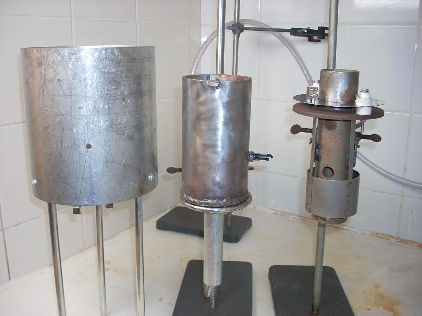
- An outer radiative-heat container of SS (an indian coffee jar from woolworths) of 15cm diameter and 15 cm long encased the cell with wound
NiCr. See figures 5 and 6.
<IMG src="http://www.sciencemadness.org/scipics/Len1/Na_fig5_6.JPG">
- Holes drilled in the radiative container with terminal posts attached to bolts drilled in the hose clamps allowed the passage of heating current
at 240V. Note its independent of electrolysis current, and is only needed at startup. A hole also passed a thermocouple probe held by a screw clamp to
the cell body. It was found that 365C was the ideal temperature for bath melting - while 320C was ideal for electrolysis. See figure 7.
<IMG src="http://www.sciencemadness.org/scipics/Len1/Na_fig7.JPG">
- The cell measured 8cm diameter x 15.5cm and held 1 kg of caustic, which although full when cold, filled it half-way when molten - this reduced
heat variation in the bath due to collector protrusion.
- A lided SS pot 25cm diameter 22cm long filled with glass wool formed the outer insulation. The pot was bolted to a long stand admitting a
receptacle which was passed cathode. See figure 8.
<IMG src="http://www.sciencemadness.org/scipics/Len1/Na_fig8.JPG">
<IMG src="http://www.sciencemadness.org/scipics/Len1/Na_fig_add2.JPG">
- The cathode was 5cm long 15mm diameter wound copper tubing. Fixed at the bottom (cool end) to a threaded nut and sealed with exhaust cement.
See figure 9.
<IMG src="http://www.sciencemadness.org/scipics/Len1/Na_fig9.JPG">
- Temperatures measured were 100C for bottom of SS pot, 66C for top, 44C for lower end of cathode stem, 33C for cathode, 150C for anode terminals,
270C for top of Na collector, 320C for bath inside collector.
- The Na was collected by a perforated ladel. This let the bath pass thru as stated - has liquid Na got a high surface tension! A lot was wasted
still clinging to the ladel - and you had to shake it really hard to get even half of it to drop into the parafin at 140C. See figure 10.
<IMG src="http://www.sciencemadness.org/scipics/Len1/Na_fig10.JPG">
- The bath current was 47 - 50A. Experiment time was about an hour to produce the sodium shown.
- The main component of the power supply, figure 11, is the transformer sourced from a cheap welder with an adjustable current screw. Welders give
20-30V or so RMS open circuit, so I had to wind down the secondary. I took a tap at 4V 8V and total 12V. About 2.2 V of that is dropped in the diodes.
These are 35A full wave bridges connected 4 in parallel to give a total capability of 140A. The PS is capable of about 70A before the transformer
(which has an aluminium secondary coil) starts overheating. The heatsink for the diodes you see is actually a bit of overkill, they hardly warm to the
touch in this arrangement at 70A. It would be better to mount the fan next to the transformer. The small red winding you see on the transformer is
power for a digital 200mV LCD meter which shows the current you see. I got a 100A shunt from Jaycar across which the LCD meter is connected directly.
It is switched with the switch you seeon the panel to show alternately the voltage/current. This is measured through a low pass filter (frequency
about 10Hz) so you get to see the mean value, rather than the useless peak.
<IMG src="http://www.sciencemadness.org/scipics/Len1/Na_fig11.JPG">
- Heater elements in radiative heaters are designed to operate at 800C plus, this does not melt the quartz tube in which they are encased, but it
will melt the fibreglass. I ran the coil at 50% power. This is provided by a variable duty triac driver. After having run the cell many times I found
the triac driver circuit is not really needed. That is because it turned out the optimum duty for the element, for exactly my type of cell, in 50% -
and this can be achieved more easily with a diode half-wave rectifier in series with the winding. The diode cannot be a 1N4004, it must be a 5 amp
variety at least.
Power Supply
The cell power supply must be capable of providing a single supply of rectified (though not necessarily smoothed) 3.3V and 4.5-4.8V RMS at 50A RMS,
with the voltage in the second range variable. It must have an associated current and voltage meter. The minimum rating of the power supply must
therefore be 240W to the load. Taking into account lead losses this is closer to 260-280W.
The simplest such power supply readily available to the amateur, is a PC supply with the 5V rail sensing made variable. However such supplies are
normally rated 250-300W, and this was considered to leave too little margin to account for variability in cell operation due to instantenous high
current demand associated with transients, such as infusion of small amounts of sodium into the anode compartment. Switching supplies are highly
intolerant of such variability when operating near their maximum rating. Hence a bridge rectified step-down transformer configuration with switchable
RMS current shunt / output voltage indicator was chosen. The power supply circuit diagram are shown below with an accompanying picture indicating
layout.
<IMG src="http://www.sciencemadness.org/scipics/Len1/Na_fig_add4.JPG">
<IMG src="http://www.sciencemadness.org/scipics/Len1/Na_fig_add3.JPG">
I have run the cell many times now, and can say its very reliable, just follow the procedure I outlined. The longest I ran the cell is 7 hours
producing 63gms Na, figure 12.
<IMG src="http://www.sciencemadness.org/scipics/Len1/Na_fig12.JPG">
The current adjusting screw, is essential, voltage control at high currents is very difficult (unless done on the primary). There is a screw on the
transformer which adjusts the position of some shunt metal in the core, to reduce or increase the amount of magnetic flux from the primary passing
thru the secondary. I have found that without such adjustment the procedure for getting sodium just doesnt work well. The cell easily overheats with
all the attendant consequences.
The holes in the collector are not critical, make them as large as you can cosnistent with structural integrity (and of course containment of the Na
at the top of the pipe). I made mine by milling 4 uniformly spaced straight channels 10mm wide by 60mm long. The collector is not floating, and is
electrically connected to the cell body at the top, at the bottom theres about a 10mm gap from the bottom of the cell, which is covered with gauze, to
allow good circulation.
Method of operation
If anyone repeats this PLEASE WEAR ENCLOSING EYE PROTECTORS. I never approach the
cell with the NaOH molten without them. Molten NaOH is one of the best materials for destroying organic tissue. A spray bit landed on my forearm,
about a 1mm sphere, and left exactly that cavity on my forearm.
If you dont follow the advice below, or your cell is constructed somewhat differently, there can be an EXPLOSION. This can eject a substantial portion
of the bath straight up the Na collector.
If this hits your Cornea - you can kiss it goodbye. And a blind experimental chemist is not a very good one.
- The temperature of the cell must be raised GRADUALLY. In all it took about 2.5 hrs from room temperature till the contents inside the collector
were liquid. AT no stage should electrolysis begin until this has occured. Heater elements in radiative heaters are designed to operate at 800C plus,
this does not melt the quartz tube in which they are encased, but it will melt the fibreglass. I ran the coil at 50% power. This is provided by a
variable duty triac driver. Once the set temperature is reached the triac is turned off. If it is required I can post a suitable circuit. You can
basically set the heating, and then go do something else for 2.5hrs.
- The bath melts at about 350C-360C as displayed by the thermocouple. This is due to the latent heat of NaOH melting as well as an unavoidable T
gradient between the thermocouple and the electrodes. Application of electrolysis current at this stage will lead to furious bubbling, and once the Na
starts forming small EXPLOSIONS. This is normal, most descriptions of Castner mention this effect. However, in a large cell such an explosion is
easily contained, doesnt eject bath, or ruin the cell. For a small cell, the explosion is of the same force, but is not well contained. It will lead
to ejection of some bath. You can see the result of that in the spray present on the cover of the pot in the first picture I posted. I have found that
explosions can be entirely avoided, so NO spatter from the cell occurs at all. The procedure is outlined below.
- Once the NaOH has melted turn of the heater. Apply electrolysis current at about 3.3V but no more. The temperature starts dropping, and the cell
electrolysis residual water in the bath. It doesnt have enough voltage to electrolyse Na. As this happens the temperature starts to drop.
- When it reaches 320C raise the mean voltage to 4.6V (you can see the actual variation of voltage across the cell in the scope trace below), the
current should approach 50A. Figure 13 shows the voltage waveform across the cell.
<IMG src="http://www.sciencemadness.org/scipics/Len1/Na_fig13.JPG">
- If the temperature rises above 325 start dropping the current by screwing in the core shunt to keep it below 330. An alteration of 1 to 2 amps
should be sufficient.
- If the temperature reaches 330C turn the electrolysis off, until its dropped to 325 (again to avoid explosions at higher temperatures due to the
fact the the Na is more mobile in the less viscous NaOH melt).
- If you overcompensated the other way and the temperature drops below 315 turn on the heater.
- When starting a new run, assuming the cell is already full from the previous run, add some NaOH so bath level remains about 4cm above the
cathode, using a funnel, into the NaOH colelctor pipe.
- Initially a brand-new ladel is a nuisance. The Na wets it perfectly and half of it stays in the ladel which is a waste. To avoid it dip the S/S
ladel into the hot NaOH bath for a minute or so, then take it out wash, and dry at 280C. This treatment will cover it with a durable black-brown oxide
cover. The Na will not stick to this.
Figure 14 shows the sodium forming in the cell, and starting to cover the NaOH bath. This picture was taken with the collector cap raised - do not
raise the cap on the collector unnecessarily, this risks both the splatter of sodium, and a fire due to escape of the protective hydrogen cloud.
<IMG src="http://www.sciencemadness.org/scipics/Len1/Na_fig14.JPG">
Purification, yield, efficiency
The sodium laddled from the cell is in the form of globules, about 1c - 2cm across, figure 15, and generally has some adhering (green) bath paricles.
<IMG src="http://www.sciencemadness.org/scipics/Len1/Na_fig15.JPG">
I have found the best method for coalesceing the globules is as follows. Once the Na has melted below the parafin surface the temperature needs to be
brought up to 140C+ to decrease the surface tension of the Na. The small globules can be sucked up by a 5ml pipete on the picture, and injected into
the larger globules. It is best if some parafin is sucked up first to reduce oxidation of the exposed Na surface at the top of the pipete. The action
needs to be performed quickly to avoid the Na solodifying in the pipete. Once one big globule is obtained, large bits of crust, which due to the
surface tension are ejected from the Na to the surface can be picked off with tweezers. When all the large bits are gone a fork can be used to trawl
through the molten ingot several times, this will collect all the oxide and small crusts to the side where it can be easily picked off. The end result
is an effectively pure Na ingot as seen in figure 16 (the slight brown precipitate on the surface, but not adhering to the sodium, is due to an
earlier attempt at coagulation using isopropyl alcohol, which did not give good results). Purification by distillation is considered inappropriate for
an amatuer set-up since the apparatus needs be completely evacuated.
<IMG src="http://www.sciencemadness.org/scipics/Len1/Na_fig16.JPG">
Initially the cell was run for 150 minutes at an average current of 47A, resulting in 24.6 gms of crude Na. Assuming 1 gram of the weight is bath
crud that gives a yield of 23.6 grams. Now 96000 Coulombs at 100% current efficiency give 23 grams of Na. In our case
47*150*60 = 432000 Coulombs.
The percentage current yield is then
(96000/432000)*(23.6/23) = 22.8%
The maximum theoretical current yield in a castner cell is 50% due to water from the anode diffusing to the cathode (where it generates H2, so
necessary to ensure the Na doesnt catch fire). And 26% is a long-term yield quoted for industrial Castner's, so the result is not bad.
Another interesting number is the cost, which depends on the energy efficiency. As stated, and despite whats written in the literature, this 'small'
Casnter cell does not need external heating during electrolysis. So the entire energy cost is the electric power. 47A at 6.4V for 150mins assuming 80%
transformer efficiency (the diode efficiency has already been accounted for in the voltage drop) is 0.94 kW-Hr. Over where I live a Kw-Hr costs 17
cents. So the cost of Na with this method is AU$6.7/Kg Na. This is VERY good.
Of course I neglected the cost of the heating current in the prior-to-electrolysis phase. Its about 12cents. So if you produce say 100gms Na in a run,
it would contribute about an extra $1.20, or $7.90 per Kg Na.
I have made some investigation of corrosion rates of different anodes in NaOH. The anode in this cell is the point most subject to attack because
- The positive anode voltage creates oxidizing conditions which tend to dissolve the anode material in the bath
- The O2 and H2O evolved at the anode tend to oxidize the anode material.
The greater concern here is contamination and shortening of bath life by the presence of anode cations in the bath, rather than the dissolution of the
anode per-se, although, using nickel in the anode has allowed the anode material to be spot welded - something I would not have been able to do if it
was subject to rapid dissolution. I have taken the cell apart after about 30hrs operation and 200gms of Na, and the nickel anode shows no signs of
corrosion whatsover. I think it can be regarded as a permanent item of the cell. The copper cathode shows more corrosion, but not really significat.
Copper can not be used in the anode, it dissolves and contaminates the bath rapidly. S/S I have used in mock-ups before. High Ni SS (which can be
detected by the fact that they are non-magnetic) seem to stand up as anodes the best. Their dissolution rate just as a very rough estimate is less
than about 100microns/hr at the current densities of this cell. The best material, without any doubt however, is the original Ni chosen by Castner.
Conclusion
I have run the cell several times and using the operating regime introduced the cell operates perfectly every time. Unlike what is generally assumed,
the cost of sodium production at AU$7.90/kg sodium with an outlay of about $200 for cell and power supply fabrication, compares favourably with
outside purchase and transport of the metal, where that is an available option.
[Edited on 24-3-2008 by len1]
[Edited on 24-3-2008 by The_Davster]This article is part of a series of
Illustrated Key Syntheses in Chemistry which I intend to post, with the purposes and guidelines outlined in the thread of the same name in the General
Chemistry section.<br> I shall attampt to ensure that the first post in all syntheses contains all the relevant information. If something
needs to be added later on, due to comments further down the thread for instance, I shall edit the first post.
Aim
It is the aim here to present an illustrated demonstration of a method for the amateur chemist to produce useful quantities of sodium metal for
laboratory use. The method relies on electrolysis of molten NaOH, a process patented by Castner in 1891, which has been found to be the simplest
method of sodium production for the amateur. The present method is a modification of the Castner process in both form and scale to enable
construction by the amateur using only materials easily obtainable from hardware stores. It is nevertheless capable of producing up to several
hundred grams per day. The present appartus is based on a simpler non-reusable cell presented on the German site .de which produced several grams
sodium per day., here modified and increased in scale to make the equipment reusable, durable and allow easy replacement of consumable elements, such
as the cathode and anode. One should note that many instances of alkali metal production using 'electrolysis in a can' have been previously
presented. While these methods can be constructed in a matter of hours they are not capable of reliably producing quantities of more than fractions
of a gram, the reason being that the electrolytic bath produces yields over a very narrow temperature range, 320-330C - for the sodium cell.
Consequently in a simple cell initial production subsequently redisolves and there is no yield. The present equipment uses the minimum amount of
sophistication necessary to achieve a consistent yield in a reusable cell.
Motivation
Sodium is an indispensible element in a serious amateur laboratory. Its primary use is in thoroughly drying organic solvents, such as Grignard
reagents, in the formation of alkoxides used in the syntheses of ethers for instance, and in the synthesis of whole groups of inorganic compounds such
as cyanides, azides, and metal amides. In the latter case, the disolution of metalic sodium in liquid ammonia produces an intense blue solution with
electronic properties similar to metals. In industry sodium is used as a heat transfer agent in situations such as nuclear power plants due to its
excelent thermal properties. Despite its plethora of uses, in the past there were no proven methods for the amateur to synthesise his own sodium
except the subgram amounts available from electrolysis in a can. This presented a problem since in many locations sodium can not be purchased OTC, for
reasons of liability and other considerations. Professional laboratories generally buy their sodium, and if it is required to be made, for reasons of
purity for instance, decomposition of NaN3 at 300C is about the only laboratory preparation available. Since NaN3 is extremely poisnous and an
explosive precursor, the availablity of sodium azide is generally poorer than that of sodium.
This leaves the amateur with industrial methods, many from the 19th century, for sodium production, methods which have generally not shown results due
generally to the difficulty of adapting industrial processes to the laboratory. These include
- vacuum reduction of sodium salts with carbon at > 1000C, such as 4NaOH + 2C -> Na2CO3 + CO + 2H2 + 2Na
- vacuum reduction with metals such as lead, magnesium or zirconium at > 500C, such as 2NaCl + Pb -> PbCl2 + 2Na
- electrolysis of NaCl + CaCl2 at 600C (Na is soluble in the bath at the mp. of NaCl) with a consumable carbon anode
- variations of the above with mobile liquid cathodes, such as molten lead or mercury to deal with reactivity of Na at 600C
- electrolysis of NaOH (due to its low mp. of 318C) with iron cathode and S/S or nickel anode 2NaOH -> 2Na + H2 + O2 (some H2O also escapes)
The latter method due to its low temperature and evolution of hydrogen gas protective to the sodium, obviates the need for a vacuum and has been found
suitable for modification to the amateur scale. The main problem which needs to be solved with this method is the extreme reactivity of molten sodium
hydroxide, which degrades almost all materials except a few metals. The basis of this method, electrolysis, was the means used by Humphry Davy the
discoverer of sodium who in 1807 electrolysed NaOH with platinum electrodes, but who was not able to produce more than subgram quantities. He in turn
owes the discovery to Alexander Volta, who six years earlier invented the battery - the voltaic pile. This new force, was immediately applied by
investigators all over Europe in an attempt to produce transformations in all kinds of materials, which previously defied change, and appeared
elementary. One such material was lye. Davy used a large pile belonging to the Royal Society, and to make lye conduct dissolved it in water, but
observed that water, rather than lye underwent transformation, and a new principal, of which there was a hint of formation at the cathode rapidly
reacted with the water. As a result Davy undertook electrolysis of the molten salt - which he cleverly melted and electrolysed with the same current.
For the next 80 years all sodium production was based on the high temperature methods above - which resulted in quick degradation of the apparatus,
and expensive sodium. In 1891 the original method of Davy was adapted for industry by Hamilton Castner, in a process bearing his name. Castner
observed that nickel was largely inert to the action of molten lye, and hence used this metal in th anode, where the positive potential in combination
with the corrosive bath acted to dissolve most other materials. If one tries to conduct the electrolysis with an overhead cathode, the molten sodium
adheres to it as it floats in the bath - and subsequent molten metal formed then attempts to form a bridge to the anode (see my experiments in the
electrochemical sodium thread) due to the potential difference in solution making this the lowest energy configuration. If one attempts to eliminate
this by using a non-conducting separator, the sodium will crawl under it, and commence forming in the anode compartment (resulting in explosions).
Hence an underside cathode - not in contact with the floating accumulated sodium - is required, and this introduces isolation and hermiticity
problems. Castner solved both these problems by using the bath material itself - a long underside stem encasing the cathode has a temperature
gradient along it, such that the bath at the bottom is solidified. The Casner cell uses an iron gauze to separate the anode and cathode below the
surface, this allows flow of ions, but not the sodium. Some sodium still manages to pass to the anode where it reacts with the oxygen formed there
and produces small explosions. The standard Castner cell is a cylinder of about 60cm diameter and 80cm high, holding about 200kg of bath.
Our cell has a diameter of 8cm and is 15cm high - a scaling down of about 250 - it holds 1.5kgs of bath, hence explosions are more serious for it -
and I have found a procedure for almost eliminating them. The current density at the electrodes is almost the same as in the original.
The only chemical on which the present method relies to produce sodium is sodium hydroxide NaOH, which is freely available OTC. Even if difficulties
arise in its purchase it can easily be manufactured from the electrolysis of salt NaCl, using a much simpler electrolysis cell than the present. It
can also be easily made using such chemicals as Na2CO3 and Ca(OH)2 in the soda lime process. Since NaCl will always be available, the consequence of
the present method is that it guarantees the same for sodium.
Note: A method described in a 1987 US patent 4725311 by
metallgesellschaft aktiengesellschaft puportedly employing reduction with magnesium at 200C appeared simpler to execute in an amateur laboratory than
any of the above. It has been tried in the unconventional sodium thread for the production of potassium following the procedure in example 1 of the
patent closely. Despite repeating the experiment several times with different sources of magnesium absolutely no alkali metal was obtained, all
observed indications of a reaction were consistent with the reaction of magnesium with water. This, combined with the obviously incorrect
measurements of evolved H2 presented in the patent, suggest the results the patent reports are false.
Findings
- 30hrs operation produced 200gms of Na, figure 1, the nickel anode shows no signs of corrosion
- The cell operates at 47-49 amps, achieving a current yield of 23% - typical for small cells, compared to 50% max theoretical current yield
- Electrical energy cost about AU$7.90/kg Na produced.
- A simple purification procedure, which produces shiny pure sodium is presented.
- A method for starting and operating the cell is presented, which completely eliminates the small explosions normally accompanying Castner
operation.
<IMG src="http://www.sciencemadness.org/scipics/Len1/Na_fig1.JPG">
Theory
The construction of a typical Castner cell (not the scaled cell for amateur use presented here) us shown in figure 2.
The following are the major reactions occuring at the cathode
- Na+ + e- -> Na(l) (-2.71V in aqueous solution)
- 2H2O +2e- -> H2 + 2OH- (-0.83V in aqueous solution)
- H2O + Na(l) -> NaOH + 1/2H2
- Na(l) + NaOH -> Na2O + 1/2H2
The following are the major reactions occuring at the anode
- 2H2O -> O2 + 4H+ 4e- (1.23V in aqueous solution)
- Ni + 2OH- -> Ni(OH)2 + 2e-
- 2Na(l) + 1/2O2 -> Na2O
- Na2O + H2O -> 2NaOH
The overall useful reaction is
- NaOH -> 1/2H2 + 1/2O2 + Na(l)
The half potentials quoted above are for aqueous reactions under standard conditions and so take into account the interaction energy of ions with
water molecules rather than with the NaOH bath at the operating temperature of the Castner cell, or indeed the overpotentials at the electrodes, they
are thus quoted for comparative purposes. One could alternatively use the formation energy of NaOH to derive the overall cell potential using DG = -
nFE, which gives a decomposition potential of 2.23V, which is more representative of the actual reaction, however this does not give us the respective
anode and cathode potentials.
The first half-cell reactions in each list are the actual desired processes leading to sodium evolution at the cathode. The actual voltage quoted for
this is 4.5V (compared to 3.94V obtained from adding the half-cell potentials, or 2.23V from the decomposition potential). Comparing this voltage to
that for the splitting of water (second cathode reaction) we see the latter occurs at a lower voltage of 2.03V under standard conditions, or
1.5V from the decomposition potential. Since water is always present in a fresh bath the initial stage of Castner cell operation is always the
electrolysis of water - until the later is eliminated. Since this proceeds at a lower voltage use is made of this fact in the present cell to avoid
production of sodium until all water has been electrolysed - as evidenced by a drop of current with the cell operating at the lower initial voltage.
This almost entirely eliminates explosions, which occur if sodium is produced with significant excess water still present in the bath. This also
serves to produce an initial protective cloud of hydrogen over the cathode. Once the all initial water has been electrolysed, the second cathode
reaction subsides, the voltage is raised, and the first cathode reaction commences. The anode reaction continues as before, and since this generates
water, the later is either electrolysed as before, or diffuses to the cathode and reacts with the sodium according to the third reaction. The effect
is the same, almost one mole of water is electrolysed for every mole of sodium (very little water can escape a dry caustic soda bath at the anode)
meaning the current efficiency of the cell is 50% maximum, based on the first cathode reaction. This can be seen explicitly from the overall reaction
of the cell. This can be a handicap when compared to the Downs cell for the electrolysis of NaCl, where one and not two moles of electrons are needed
to reduce one mole of sodium. This, as well as the fact that NaOH is overwhelmingly produced by electrolysis of common salt, means that the Downs
process has replaced Castner almost everywhere.
The second anode reaction represents degradation of the cell anode. Nickel has a large potential in sodium hydroxide, and is chosen as the anode
material for this reason.
Excess voltage, over that quoted above needs to be applied to the cell to overcome voltage drops due to ohmic losses and electrode overpotentials.
The cathode represents a copper spiral 50mm long and 21mm diameter, the anode is also cylindrical, with a diameter of 70mm. Since the conductivity of
molten NaOH is quoted at 2.1 Ohm-1cm-1, the resistance of the present cell is (1/2 Pi 2.1) * ln(70/21)/5 = 0.019 Ohm. To pass the standard cell
current of 47 Amp a voltage drop of 1V is then required. This power goes towards heating the cell - its not really wasted since it replaces heat
conduction losses and keeps the bath molten. This results in the convenient outcome, that after initial heating needed to melt the bath, subsequently
the temperature is maintained by the electrolysis current, in commercial Casner cells, as wee as here.
<IMG src="http://www.sciencemadness.org/scipics/Len1/Na_fig2.JPG">
Method
All reactions were carried out at an ambient temperature of 20C
Theory of construction
As mentioned in the introduction, the present construction is inspired by a pilot Castner cell presented in the German forum .de, to which the reader
is referred. Problems identified with that design, which prevent reuse of equipment for more than one run and result in limited production, were
- fairly flimsy nature of apparatus - the Na collector just sits in the melt - if you heat it too high, it will move.
- The container walls are used as an anode, which is not how Castner operates, leading to wall erosion, as well as making it impossible to use
nickel in the anode, by far the most sturdy material when it comes to dissolution under potential in molten NaOH
- The bottom of the vessel was ramed clay, exposed directly to NaOH at near melting temperature - although the original experiment tried to
maintain a temperature differential so the bottom NaOH is solid, in practice its hard to do, and in any case at elevated temperatures the clay will
rapidly dissolve (my experinments show molten NaOH attacks clay at the order of 1mm per 10 mins). The dissolution of the clay leads to substantial
contamination of the bath, shortens its life, as well as leading to perforation at the bottom with time.
- The low amperage of the cell resulting from (3) means you have to wait all day to get even a few grams of Na.
A 3D drawing of the salient features of the cell and a table listing the appropriate materials and dimensions is given below. This is not a
CAD scaled technical drawing, which would not be appropriate here. However adequate information is provided to enable the cell to be reproduced using
the 3D drawing, the many photographs, and the dimensions given in the table.
<IMG src="http://www.sciencemadness.org/scipics/Len1/Na_fig_add1.JPG">
Essential Components Length / Diameter / Thickess, in mm
- Cell Wall Carbon Steel Cylinder 160 / 80 / 5
- Collector Carbon Steel Cylinder 200 / 50 / 5
- Cell Bottom Carbon Steel Disk 90 / 5 with 24mm centre hole for cathode stem
- Cell Top Carbon Steel Disk 100 / 5 with 51mm centre hole for collector
- Stem Carbon Steel Cylinder 250 / 27 / 2
- Anode Nickel Cylinder 50 / 70 / 1
- Cathode Copper Wire/Pipe 550 / / 2 top is 18mm helix with 5 turns, bottom 290mm straight
- Heat Shield Stainless Steel Pot 130 / 130 / 0.7 with 92mm centre hole for cell wall
- Insulating Pot Stainless Steel Pot 230 / 220 / 0 with 28mm centre hole for cathode stem
Several areas of the original construction are used here unchanged
- The cathode was made of wound Cu tube of short cross section rather than solid. That is a great idea comapred to a solid Cu cathode- meaning
much reduced heat loss through Cu notorious heat conductivity, a much more unifrom temperature of the bath, which is essential for any reasonable
yield in this case.
- The Na collector was a slotted pipe into which a thin wire gauze (sold for toasters) was inserted, and held up extremely well.
- The cell was heated from the outside with insulation provided by fibreglass.
The present construction has the following features:
- A cylinder anode of 1mm Ni sheet of 6cm diameter by 5 cm long attached by adjustable SS bolts to a top circular plate separated from the
collector and casing by ceramic insulators scavanged from a radiation heater. See figure 3.
<IMG src="http://www.sciencemadness.org/scipics/Len1/Na_fig3.JPG">
- A NiCr heating element scavanged from the same heater wound around fibreglass matting and providing 300W of power. The fibregalss was held in a
wound state around the outside of the cell by two stainless steel hose clips. Each of the hoseclips also acted as a terminal for the heating element.
This provides a sturdy constrcution. See figure 4.
<IMG src="http://www.sciencemadness.org/scipics/Len1/Na_fig4.JPG">
- An outer radiative-heat container of SS (an indian coffee jar from woolworths) of 15cm diameter and 15 cm long encased the cell with wound
NiCr. See figures 5 and 6.
<IMG src="http://www.sciencemadness.org/scipics/Len1/Na_fig5_6.JPG">
- Holes drilled in the radiative container with terminal posts attached to bolts drilled in the hose clamps allowed the passage of heating current
at 240V. Note its independent of electrolysis current, and is only needed at startup. A hole also passed a thermocouple probe held by a screw clamp to
the cell body. It was found that 365C was the ideal temperature for bath melting - while 320C was ideal for electrolysis. See figure 7.
<IMG src="http://www.sciencemadness.org/scipics/Len1/Na_fig7.JPG">
- The cell measured 8cm diameter x 15.5cm and held 1 kg of caustic, which although full when cold, filled it half-way when molten - this reduced
heat variation in the bath due to collector protrusion.
- A lided SS pot 25cm diameter 22cm long filled with glass wool formed the outer insulation. The pot was bolted to a long stand admitting a
receptacle which was passed cathode. See figure 8.
<IMG src="http://www.sciencemadness.org/scipics/Len1/Na_fig8.JPG">
<IMG src="http://www.sciencemadness.org/scipics/Len1/Na_fig_add2.JPG">
- The cathode was 5cm long 15mm diameter wound copper tubing. Fixed at the bottom (cool end) to a threaded nut and sealed with exhaust cement.
See figure 9.
<IMG src="http://www.sciencemadness.org/scipics/Len1/Na_fig9.JPG">
- Temperatures measured were 100C for bottom of SS pot, 66C for top, 44C for lower end of cathode stem, 33C for cathode, 150C for anode terminals,
270C for top of Na collector, 320C for bath inside collector.
- The Na was collected by a perforated ladel. This let the bath pass thru as stated - has liquid Na got a high surface tension! A lot was wasted
still clinging to the ladel - and you had to shake it really hard to get even half of it to drop into the parafin at 140C. See figure 10.
<IMG src="http://www.sciencemadness.org/scipics/Len1/Na_fig10.JPG">
- The bath current was 47 - 50A. Experiment time was about an hour to produce the sodium shown.
- The main component of the power supply, figure 11, is the transformer sourced from a cheap welder with an adjustable current screw. Welders give
20-30V or so RMS open circuit, so I had to wind down the secondary. I took a tap at 4V 8V and total 12V. About 2.2 V of that is dropped in the diodes.
These are 35A full wave bridges connected 4 in parallel to give a total capability of 140A. The PS is capable of about 70A before the transformer
(which has an aluminium secondary coil) starts overheating. The heatsink for the diodes you see is actually a bit of overkill, they hardly warm to the
touch in this arrangement at 70A. It would be better to mount the fan next to the transformer. The small red winding you see on the transformer is
power for a digital 200mV LCD meter which shows the current you see. I got a 100A shunt from Jaycar across which the LCD meter is connected directly.
It is switched with the switch you seeon the panel to show alternately the voltage/current. This is measured through a low pass filter (frequency
about 10Hz) so you get to see the mean value, rather than the useless peak.
<IMG src="http://www.sciencemadness.org/scipics/Len1/Na_fig11.JPG">
- Heater elements in radiative heaters are designed to operate at 800C plus, this does not melt the quartz tube in which they are encased, but it
will melt the fibreglass. I ran the coil at 50% power. This is provided by a variable duty triac driver. After having run the cell many times I found
the triac driver circuit is not really needed. That is because it turned out the optimum duty for the element, for exactly my type of cell, in 50% -
and this can be achieved more easily with a diode half-wave rectifier in series with the winding. The diode cannot be a 1N4004, it must be a 5 amp
variety at least.
Power Supply
The cell power supply must be capable of providing a single supply of rectified (though not necessarily smoothed) 3.3V and 4.5-4.8V RMS at 50A RMS,
with the voltage in the second range variable. It must have an associated current and voltage meter. The minimum rating of the power supply must
therefore be 240W to the load. Taking into account lead losses this is closer to 260-280W.
The simplest such power supply readily available to the amateur, is a PC supply with the 5V rail sensing made variable. However such supplies are
normally rated 250-300W, and this was considered to leave too little margin to account for variability in cell operation due to instantenous high
current demand associated with transients, such as infusion of small amounts of sodium into the anode compartment. Switching supplies are highly
intolerant of such variability when operating near their maximum rating. Hence a bridge rectified step-down transformer configuration with switchable
RMS current shunt / output voltage indicator was chosen. The power supply circuit diagram are shown below with an accompanying picture indicating
layout.
<IMG src="http://www.sciencemadness.org/scipics/Len1/Na_fig_add4.JPG">
<IMG src="http://www.sciencemadness.org/scipics/Len1/Na_fig_add3.JPG">
I have run the cell many times now, and can say its very reliable, just follow the procedure I outlined. The longest I ran the cell is 7 hours
producing 63gms Na, figure 12.
<IMG src="http://www.sciencemadness.org/scipics/Len1/Na_fig12.JPG">
The current adjusting screw, is essential, voltage control at high currents is very difficult (unless done on the primary). There is a screw on the
transformer which adjusts the position of some shunt metal in the core, to reduce or increase the amount of magnetic flux from the primary passing
thru the secondary. I have found that without such adjustment the procedure for getting sodium just doesnt work well. The cell easily overheats with
all the attendant consequences.
The holes in the collector are not critical, make them as large as you can cosnistent with structural integrity (and of course containment of the Na
at the top of the pipe). I made mine by milling 4 uniformly spaced straight channels 10mm wide by 60mm long. The collector is not floating, and is
electrically connected to the cell body at the top, at the bottom theres about a 10mm gap from the bottom of the cell, which is covered with gauze, to
allow good circulation.
Method of operation
If anyone repeats this PLEASE WEAR ENCLOSING EYE PROTECTORS. I never approach the
cell with the NaOH molten without them. Molten NaOH is one of the best materials for destroying organic tissue. A spray bit landed on my forearm,
about a 1mm sphere, and left exactly that cavity on my forearm.
If you dont follow the advice below, or your cell is constructed somewhat differently, there can be an EXPLOSION. This can eject a substantial portion
of the bath straight up the Na collector.
If this hits your Cornea - you can kiss it goodbye. And a blind experimental chemist is not a very good one.
- The temperature of the cell must be raised GRADUALLY. In all it took about 2.5 hrs from room temperature till the contents inside the collector
were liquid. AT no stage should electrolysis begin until this has occured. Heater elements in radiative heaters are designed to operate at 800C plus,
this does not melt the quartz tube in which they are encased, but it will melt the fibreglass. I ran the coil at 50% power. This is provided by a
variable duty triac driver. Once the set temperature is reached the triac is turned off. If it is required I can post a suitable circuit. You can
basically set the heating, and then go do something else for 2.5hrs.
- The bath melts at about 350C-360C as displayed by the thermocouple. This is due to the latent heat of NaOH melting as well as an unavoidable T
gradient between the thermocouple and the electrodes. Application of electrolysis current at this stage will lead to furious bubbling, and once the Na
starts forming small EXPLOSIONS. This is normal, most descriptions of Castner mention this effect. However, in a large cell such an explosion is
easily contained, doesnt eject bath, or ruin the cell. For a small cell, the explosion is of the same force, but is not well contained. It will lead
to ejection of some bath. You can see the result of that in the spray present on the cover of the pot in the first picture I posted. I have found that
explosions can be entirely avoided, so NO spatter from the cell occurs at all. The procedure is outlined below.
- Once the NaOH has melted turn of the heater. Apply electrolysis current at about 3.3V but no more. The temperature starts dropping, and the cell
electrolysis residual water in the bath. It doesnt have enough voltage to electrolyse Na. As this happens the temperature starts to drop.
- When it reaches 320C raise the mean voltage to 4.6V (you can see the actual variation of voltage across the cell in the scope trace below), the
current should approach 50A. Figure 13 shows the voltage waveform across the cell.
<IMG src="http://www.sciencemadness.org/scipics/Len1/Na_fig13.JPG">
- If the temperature rises above 325 start dropping the current by screwing in the core shunt to keep it below 330. An alteration of 1 to 2 amps
should be sufficient.
- If the temperature reaches 330C turn the electrolysis off, until its dropped to 325 (again to avoid explosions at higher temperatures due to the
fact the the Na is more mobile in the less viscous NaOH melt).
- If you overcompensated the other way and the temperature drops below 315 turn on the heater.
- When starting a new run, assuming the cell is already full from the previous run, add some NaOH so bath level remains about 4cm above the
cathode, using a funnel, into the NaOH colelctor pipe.
- Initially a brand-new ladel is a nuisance. The Na wets it perfectly and half of it stays in the ladel which is a waste. To avoid it dip the S/S
ladel into the hot NaOH bath for a minute or so, then take it out wash, and dry at 280C. This treatment will cover it with a durable black-brown oxide
cover. The Na will not stick to this.
Figure 14 shows the sodium forming in the cell, and starting to cover the NaOH bath. This picture was taken with the collector cap raised - do not
raise the cap on the collector unnecessarily, this risks both the splatter of sodium, and a fire due to escape of the protective hydrogen cloud.
<IMG src="http://www.sciencemadness.org/scipics/Len1/Na_fig14.JPG">
Purification, yield, efficiency
The sodium laddled from the cell is in the form of globules, about 1c - 2cm across, figure 15, and generally has some adhering (green) bath paricles.
<IMG src="http://www.sciencemadness.org/scipics/Len1/Na_fig15.JPG">
I have found the best method for coalesceing the globules is as follows. Once the Na has melted below the parafin surface the temperature needs to be
brought up to 140C+ to decrease the surface tension of the Na. The small globules can be sucked up by a 5ml pipete on the picture, and injected into
the larger globules. It is best if some parafin is sucked up first to reduce oxidation of the exposed Na surface at the top of the pipete. The action
needs to be performed quickly to avoid the Na solodifying in the pipete. Once one big globule is obtained, large bits of crust, which due to the
surface tension are ejected from the Na to the surface can be picked off with tweezers. When all the large bits are gone a fork can be used to trawl
through the molten ingot several times, this will collect all the oxide and small crusts to the side where it can be easily picked off. The end result
is an effectively pure Na ingot as seen in figure 16 (the slight brown precipitate on the surface, but not adhering to the sodium, is due to an
earlier attempt at coagulation using isopropyl alcohol, which did not give good results). Purification by distillation is considered inappropriate for
an amatuer set-up since the apparatus needs be completely evacuated.
<IMG src="http://www.sciencemadness.org/scipics/Len1/Na_fig16.JPG">
Initially the cell was run for 150 minutes at an average current of 47A, resulting in 24.6 gms of crude Na. Assuming 1 gram of the weight is bath
crud that gives a yield of 23.6 grams. Now 96000 Coulombs at 100% current efficiency give 23 grams of Na. In our case
47*150*60 = 432000 Coulombs.
The percentage current yield is then
(96000/432000)*(23.6/23) = 22.8%
The maximum theoretical current yield in a castner cell is 50% due to water from the anode diffusing to the cathode (where it generates H2, so
necessary to ensure the Na doesnt catch fire). And 26% is a long-term yield quoted for industrial Castner's, so the result is not bad.
Another interesting number is the cost, which depends on the energy efficiency. As stated, and despite whats written in the literature, this 'small'
Casnter cell does not need external heating during electrolysis. So the entire energy cost is the electric power. 47A at 6.4V for 150mins assuming 80%
transformer efficiency (the diode efficiency has already been accounted for in the voltage drop) is 0.94 kW-Hr. Over where I live a Kw-Hr costs 17
cents. So the cost of Na with this method is AU$6.7/Kg Na. This is VERY good.
Of course I neglected the cost of the heating current in the prior-to-electrolysis phase. Its about 12cents. So if you produce say 100gms Na in a run,
it would contribute about an extra $1.20, or $7.90 per Kg Na.
I have made some investigation of corrosion rates of different anodes in NaOH. The anode in this cell is the point most subject to attack because
- The positive anode voltage creates oxidizing conditions which tend to dissolve the anode material in the bath
- The O2 and H2O evolved at the anode tend to oxidize the anode material.
The greater concern here is contamination and shortening of bath life by the presence of anode cations in the bath, rather than the dissolution of the
anode per-se, although, using nickel in the anode has allowed the anode material to be spot welded - something I would not have been able to do if it
was subject to rapid dissolution. I have taken the cell apart after about 30hrs operation and 200gms of Na, and the nickel anode shows no signs of
corrosion whatsover. I think it can be regarded as a permanent item of the cell. The copper cathode shows more corrosion, but not really significat.
Copper can not be used in the anode, it dissolves and contaminates the bath rapidly. S/S I have used in mock-ups before. High Ni SS (which can be
detected by the fact that they are non-magnetic) seem to stand up as anodes the best. Their dissolution rate just as a very rough estimate is less
than about 100microns/hr at the current densities of this cell. The best material, without any doubt however, is the original Ni chosen by Castner.
Conclusion
I have run the cell several times and using the operating regime introduced the cell operates perfectly every time. Unlike what is generally assumed,
the cost of sodium production at AU$7.90/kg sodium with an outlay of about $200 for cell and power supply fabrication, compares favourably with
outside purchase and transport of the metal, where that is an available option.
[Edited on 24-3-2008 by len1]