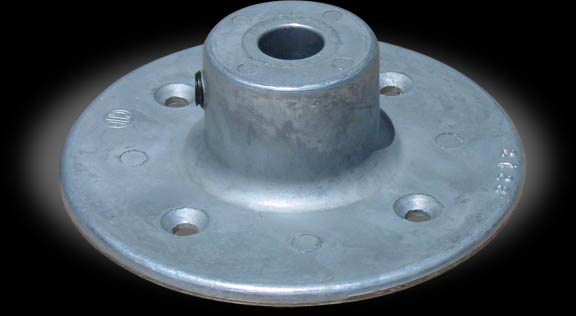
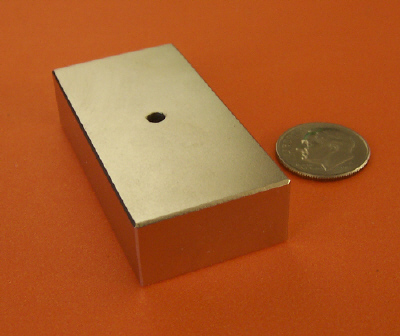
Sciencemadness Discussion Board

DIY magnetic stirrer

 Pages:  1  

thatlittleguy - 19-12-2004 at 18:18

I have seen plans for a home-brew mag. stirrer that many of you are probably pretty well familiar with. Has anyone out there tried to place this in the body of a hotplate? Success or no? Elec. motors don't like heat, do they? maybe a ceramic plate in between?


E.b.C: Title

[Edited on 15-4-2005 by chemoleo]

thatlittleguy - 19-12-2004 at 19:32

Well....maybe not so pretty well familiar. I'll try attaching it?

magstirrer.gif - 74kB

BromicAcid - 19-12-2004 at 19:51

Before I invested in a good hotplate stirrer I used a home aid stirring mechanism in tandem with a range coil heater. I would take the range and sit it directly on top of my encased electric stirrer and never had a problem stirring the mixture on the other side of the heating element. I never thought to combine the two because some things needed stirring without heating, and some heating without stirring and I thought it novel that I could do each individually, additionally my stirring mechanism took a 12 V power source and the hot plate 120V so there would have still been two plugs. In my organic chemistry class we also took our heating mangles and set them on stirring apparatuses stirring through the heating mantle. It was just easier this way.

As for incorporation, the inside of a hotplate isn't too bad, there is a metal plate below the actual coil, and heat has a tendency to rise, so if you put the mechanism within, as long as it didn't come into contact with the reflective plate for the heat I wouldn't see a problem. Just don't go using a sand bath. I realize that in order to add your attachment you had to make another post, but please be mindful of adding attachements in the first place. Yes, many of use know of that design from rhodium, also, many of us could come up with something similar on our own.

[Edited on 12/20/2004 by BromicAcid]

The_Davster - 22-1-2005 at 21:23

Here is something I made a year or so ago. The beaker size is 600mL.

Be kind:P

stirrer.jpg - 28kB

jimwig - 23-1-2005 at 13:59

somewhat vague but you may get the idea:

http://www.geocities.com/jimwig2000/diy-mag-stirrer.html

all the parts except the motor and housing are present in most discarded speakers.


[Edited on 23-1-2005 by jimwig]

Mendeleev - 25-1-2005 at 05:34

Quote:

Here is something I made a year or so ago.


Ha ha ha he *snort* *tear* ha ha ha.

Ahem, sorry, I really like it, it's just kind of funny :P.

frogfot - 25-1-2005 at 09:42

The main problem with conventional hot plate and a magnetic stirrer is the shielding of magnetic field.. so the plate should be done out of aluminium (or other nonmagnetic metal).
The only source for this I could find was from 1,3kW iron (all modern irons have Al heating plates). But since it had a safety on about 225*C I was afraid to heat it further.. Any idea if such heating plates will survive if set on maximum (directly to 230V)?

Would be great to put one of those plates on a homemade dimmer..

chemoleo - 25-1-2005 at 11:59

Well i wouldn't quite do that.
You might want to take out the coil/resistance heater, and connect it to the mains with a powerregulator before that. Most can bear low red heat. I am sure you will find a powersetting that keeps this at low red heat.

Didn't someone post a nice stirrer before, from brainfever?

[Edited on 25-1-2005 by chemoleo]

bio2 - 25-1-2005 at 13:28

Irons also make good melting point apparatus!

The irons I have seen have the element integral (cast) as part of the assembly. So good luck trying to remove the wire!

These should easily take 400-500deg but would likely burn-out running flat out especially with no load. Take your triac phase controller (dimmer) rated at least to the full output and determine the setting required for the temp you want. Then put a resistor (trim pot) in series with the main pot to limit the maximum output. You could also feed a half wave rectifier to reduce the ouput by about half or use a NTC thermistor (surge limiter type) in series to not only give a soft start but also a series resistance. Most commercial heating mantles are designed for a maximum element temp of 450deg. If you can see the end of the wire and determine the guage then calc the temp. I posted a NiCr wire helix calculator a few days ago that makes this very easy.

Good luck and don't forget Ohms Law or you will be producing a lot of smoke.:o

frogfot - 26-1-2005 at 09:59

Bio, you're right, it's cast.
If it can take up to 500*C, it's nearly as a kitchen stove.
Reason I thoat that it would be ok to connect it directly to 230V is because that's how the iron was made originally.. Temp in my iron is controlled by a small bimetal piece, so coil have only two modes, on and off.
I also think that wire reaches it's highest temp in seconds, so logically thinking, it actually shouldn't matter for how long I will keep it on maximum setting.. it have to be designed for maximum power!
Making a good heat isolation from the electronics/magnet is another story..

I'm not so good in electronics.. do you think that triac phase controller schematics in this pdf (fig 1, application schematic) is ok in my application:
http://www.onsemi.com/pub/Collateral/UAA2016-D.PDF

Though I don't really understand what's NTC resistance for..

The_Davster - 26-1-2005 at 15:09

Quote:
Originally posted by Mendeleev
Ha ha ha he *snort* *tear* ha ha ha.

Ahem, sorry, I really like it, it's just kind of funny :P.


Hey, it is not THAT funny, the popsicle sticks keep the beaker from vibrating off the surface. If you think that is bad before I put lead weights under the cardboard box that it is construced out of the damn thing would run around on the table.:D
And the ducttape, that is just for the aesthetic appeal, and waterproofing, the thing is made of cardboard after all;)

This will just make everyone laugh harder:( :D:P

PS: I do have plans to make a metal one but that is on a very long 'to do' list.

[Edited on 26-1-2005 by rogue chemist]

bio2 - 26-1-2005 at 15:55

http://www.teccor.com/cgi-bin/r.cgi/prod_series.html?LFSESSI...

Check out the app. notes on this page. All you will ever need to know to design phase controllers. The zero switch is to minimize RF interference and is not essential or required.

Just get the cheapest dimmer you can find that has a wattage rating near your load but this is not so easy as most are 600w.
However if you can find the el-cheapo $3 ones then get a couple and find the rating of the triac. Some actually have 8amp triacs but are downrated because the heat sink is so small. Advantage here is you have the board, pot, enclosure etc. so it's easy to add just a few parts and make it really usefull. If you like doing this kind off stuff then get a temp sensor and a optical isolator for a variable power temp controller. I have a few made from the hardware store junk (IMHO) dimmers. You can pick up a 20A triac these days for just a few bucks. I have a nice 3phase 480V one using the 40A alternistor triacs. Now that's usefull wattage and it turns down to 2%. Check my other posts on this. Have fun!

More later kinda busy

frogfot - 15-2-2005 at 05:34

How about an external electrical magnetic stirrer? I've drawed the whole thing to ease the explanation:
http://img.photobucket.com/albums/v113/frogfot/magnstir.gif

So we got an iron ring with 4 fat bolts. 4 coils are winded on those bolts. By simply changing the current direction (as given in pic) we can rotate a magnet inside. Just like in a stepper motor..
The iron ring can be easily done from a "construction band", sold in hardware store.. Purpose of it is to "transport" magnetic field. Well it should be more effective that way.

Though I dunno how big currents this thing would eat.. probably alot..

This thing would have many advantages, if it could work that is.. It can be placed on any stove/hotplate (couple of cm of air is enough isolation). There are no moving parts..

Is there a chance it will work?

Btw, still didn't make any dimmer..

[Edited on 15-2-2005 by frogfot]

Quince - 11-3-2005 at 10:55

Not to fall behind, I built this little guy, shown in the attachment on the slowest setting:

slow.jpg - 36kB

Quince - 11-3-2005 at 10:57

And this attachment shows the fastest setting:

fast.jpg - 36kB

Quince - 11-3-2005 at 10:58

The last attachment shows the insides. The power is from a small 9 V DC wall wart. Notice how small the motor is, yet it was still going too fast (this was true with any motors), so I used a 3:1 geardown (the rubber band), which makes speed more reasonable and increases torque, so the heavy plate and magnets speed up faster.

A better stirrer would use induction drive, as you see in aquarium pumps, and would thus have no moving parts to wear down.

open.jpg - 33kB

Let me show off my latest project:

BrAiNFeVeR - 15-3-2005 at 14:12

http://www.geocities.com/brainfevert/heatstir.html

In the link above you will find my totally homemade heater/stirrer combo unit.

Comments or questions are welcome.

Quince - 15-3-2005 at 15:02

Nice! Now you just need a PID temperature controller...

LOL, when I first opened the page, I thought the first picture was it.

BrAiNFeVeR - 16-3-2005 at 01:36

temperature controlling seemed kinda hard to fit in ... but I may add an IR thermometer later.

Making the digital IR thermometer control the varistor sounds pretty hard to do though ...


If you have interesting hints or ideas about this I'd love to hear them.

I'm baptising the mantle today with it's first destillation :)

Quince - 16-3-2005 at 18:27

You can always add it later. Here's my plan, and I will post a circuit when I finish it (I have a queue of a few other project to finish first, though...)

Now, you said you will using an infrared sensor. My question to you is, since you are not dealing with a blackbody due to reflected light (some will be reflected in IR), wouldn't this be inaccurate at low temperatures? Why not use a thermocouple?

For temperature control, you can buy a PID for $100-$150. The advantage is that it is programmable. The disadvantage is that it's not DIY and the money could be spent on better things.

I plan to build my own. First I need an electronic thermometer. I will use a thermocouple, and its cold junction temperature will be known because I'll use an LM335 sensor besides it, and a simple circuit will give me Centigrade scale temperature accurate to about 1*C. The output goes into the PID circuit (a voltmeter can be attached for a display so you don't need another thermometer to read off). The thermocouple probe is best enclosed in glass, but I'll just use Teflon, since I haven't gotten the hang of melting glass yet...

The details of making a simple PID are shown here:
http://www.sensorsmag.com/articles/0504/52/main.shtml
The reason you don't just want proportional (P) is that the slow response of the system (long chain: heater-to-flask-to-solution-to-thermocouple) means there will be too much overshooting and temperature instability, in my opinion. The extra control is nice, in any case; for example, consider that when you are boiling, you want to adjust the heating rate, rather than the controller just pumping at max because it's trying to reach some temperature that's impossible until the liquid boils off. All those variable resistors in Fig 1 are controls.

The output of this drives a PWM (can be made with a mere NE555) and that drives the optocoupler (safety first!) and then the heater's triac.

Using a SPICE simulator makes for less troubleshooting during build time. Linear's SwitcherCAD III is a good free one. If you have a few grand to burn, go for Micro-Cap 8 :D :D :D

[Edited on 17-3-2005 by Quince]

BrAiNFeVeR - 20-3-2005 at 14:21

First off, I'm not all that good with electronics, so I could make very little of the last part of your post. (from "the output" on)

Secondly, any sensor that would require to be inside the liquid is impossible as that will make my destillation setup (the projects main goal) no longer airtight (no fun with HNO3).

I have absolutely NO cash to burn. Anything going over €50 is out of the question for this project.
During first destillation tests, I regulated the current by hand, and found this fairly reliable.


One possibility might be to place the thermocouple in the position of the NS14 Hg-thermometer.


If one where to automate the destillation proces, could it be something like this?:

At the beginning, it will give full heating power (3 to 4 Amps) untill T reaches a set point, at which the unit sets the power back to a set "cruise power" (1.75 to 2.5 Amps).
If the temperature drops, cruise power setting is altered to a slightly higher value. If the temperature rises beyond a certain point, power is turned off completely, and a signal is given that the destillation proces is complete.

BrAiNFeVeR - 23-3-2005 at 14:40

<pm Quince>

Subject: Re: DIY mag. stirrer
From: Quince
To: BrAiNFeVeR
Sent: 22-3-2005 at 03:27
Message: I am replying by U2U since I can't post. Perhaps you can help me and ask Vulture to reinstate my posting ability.

The thermocouple can be inserted as any glass/mercury thermometer. A PTFE or glass tube is all you need (probably easier to seal the glass). Then just use it with your thermometer adapter and you can have an airtight seal.

The parts for the thermocouple/controller should add up to less than $20, with the possible exception of a temperature display (so you don't need both thermocouple and thermometer). You can just use an old analog voltmeter for that.

Please post my reply in the thread so others can see it.

</pm Quince>

My reply:

First off; I'm no mod and I don't know why your ability to post was taken, but I can't do anything about it.

I'm aware of the existance and use of thermocouples and Pt100/1000, but any kind of temperature and destillation automatisation is too complex a work for the seldom destillations I do.

It would take more research and work then it would be used distilling.

It would be a cool project, but finding the courage to commence with it (research and test) and see it trough (placement in my setup and regulating) is not the kind of thing I see happening within a few months time.

Quince - 14-4-2005 at 20:47

Soldering the heater wire for a mantle is out of the question, as it will melt away. Pressure joints are problematic, as oxidation layers can form between the surfaces, wrecking the connection eventually. Spot welding is difficult without the proper equipment. Best is to braze.

I had no brazing alloy, so I just used silver. I used the nichrome ribbon from a toaster, but put the parts in series instead of parallel as it was in the toaster -- you don't need as high a temperature as the toaster reaches (plus, it is harder on the fiberglass loom). The silver melts easily in a propane torch. It wouldn't stick well to the nicrhome, so I melted in just a bit of copper and solder. Regular soldering flux doesn't work since it burns away too fast in the torch, so I used borax powder in a bit of alcohol. Overall, it worked great.

Driving a triac the usual way doesn't give power proportional to the potentiometer position. It's best to use a PWM to drive the triac. I have attached a schematic of my solution; the two 25 K resistors represent a 50 K pot (actually a higher value gives more linear response, use 200 K pot and change the 1 K resistors to 2 K). Adjust C1 to change the frequency.

The output is fed into the circuit of figure 7 or 8 here.

For electronic control, set the pot to the middle position, and feed a control voltage to the CV pin (range 0-Vcc). That allows control from say a PID or computer or whatever.

Quince - 14-4-2005 at 20:48

Forgot the attachment. For some reason, the edit feature doesn't allow me to add one.

PWM.png - 25kB

frogfot - 15-4-2005 at 00:23

Cool, that controller seems to be easy to make. I got some questions though..
What's the purpose of that MOC30xx thingy, is it really necessary? and where is it's input, is it on pin 2 instead of the AND?
Oh, and what's that round thingy "V1" in 555 timer circuit?

Sorry for all questions.. :)

Quince - 15-4-2005 at 00:48

V1 is a voltage source. That's a very common symbol so you should remember it.

Check the NE555 datasheet for acceptable voltages. Better run the simulator to make sure everything works right with the parts values and voltages you are using. The one pictured is good and completely free.

Yes, you connect it instead of the NAND. That gate seems to be shown there to indicate that you are using a logic signal. Again, make sure you are using compatible voltages so you don't fry something, and reformat the signal if needed. Rin needs to be set to create the proper current through the emitter; currents are given in the datasheet.

DO NOT drive the triac directly! It is not safe; you need the optical isolation; it is almost as bad as cutting off the grounding prong of a three-prong power cord to fit an ungrounded outlet (though the latter is actually illegal). Also, the two main terminals on a triac are not interchangeable, so make sure you check the datasheet of whatever triac you use.

I'll probably build a PID and thermocouple thermometer that can be added for awesome control, and I'll post these when ready.

Anyone use mantles with flat bottomed flasks and beakers? It kind of sucks having to get both a mantle AND a hotplate. Is the air gap under the bottom of a flat bottom vessel and the mantle a problem, other than slowing down the response?

[Edited on 15-4-2005 by Quince]

Quince - 18-4-2005 at 04:55

Values changed in schematic. Use a 250K pot instead of 50K and remove R2. An input signal at the pot wiper, through a 250K resistor, will also control the PWM (with pot set to center), but it's not quite a linear correspondance with the control voltage, which might throw off a PID. Maybe I'll post something better later.

12AX7 pointed out (thanks) that a triac doesn't shut off until a zero crossing of the AC going through it. That means that PWM will only work at a good deal lower frequency than the power line's. I'm thinking a MOSFET switch may work, as in the attachment (simulates OK, but I've not built it so don't put much stock in it).

The voltage source in there (on the right) stands for the driver (PWM through optocoupler or small transformer for isolation). On the left is obviously the mains frequency; the amplitude says 169 instead of 120 since LTSpice uses peak rather than RMS (for sine wave it's by a factor of sqrt(2)). R3 is load and R2 is because mains neutral is tied to ground in North America (as in, it's already in your house wiring, I just chose some arbitrary resistance to represent that connection).

This should work fine with a heater as load (such as a heating mantle). As for other loads...should be fine as light bulb dimmer, and for other 'slow', dumb loads (that 'integrate' the supply). No clue if it will work with AC motors. Wouldn't try transformers or electronics as load either, as they depend on a normal-looking AC.

[Edited on 18-4-2005 by Quince]

ac_ss_relay.png - 39kB

FrankRizzo - 20-4-2005 at 18:15

Quince,

This cheap PID available from Meci.com might be of interest. Unfortunately, customer service there doesn't have any specs for it, but it may be useful. I ran across it when searching for PID's for my RIMS brewing setup.

http://www.meci.com/Catalog/Item/7c239168-af45-43bc-9795-505...


Back OT, the following sites have some good info on stir plates:

http://brewiki.org/StirPlate
http://www.frontier.iarc.uaf.edu/~cswingle/brewing/equipment...


[Edited on 21-4-2005 by FrankRizzo]

Quince - 28-4-2005 at 20:10

Well I had used plaster of paris for the mantle bowl but it broke too easily. I see BrAiNFeVeR (what kind of brain fever did you have, BTW, meningitis or encephalitis? viral or bacterial? :P ) used concrete. Can I use clay? Actually, I don't have clay either, but what if I crush up some earthenware pots, can I make clay from that and bake it in my kitchen stove?

12AX7 - 28-4-2005 at 23:57

LOL, no that'll be grog. Grog has no binding power. You need real clay, either from the ground or the local pottery store. Then it needs to be "baked" upwards of yellow heat, preferably a good yellow-white. That'll get you in the cone 6 to 12 area which has good strength and density for most clays (assuming it hasn't melted yet).

Tim

Quince - 29-4-2005 at 00:45

I don't have a kiln. What's the alternative? Is air-dry clay good enough for a mantle base, or will the heat damage it?

[Edited on 29-4-2005 by Quince]

Magnetic stirrer made from broken diskdrive.

Tacho - 8-5-2005 at 09:09

Almost all you need to make a magnetic stirrer is in that old HDD you just didn't have the courage to throw in the garbage.

Here... attached.

Attachment: hddstirrer.pdf (192kB)
This file has been downloaded 2741 times


Triac as rate controller instead of phase controller

Rosco Bodine - 10-5-2005 at 06:34

Most lamp dimmer type circuits are phase controllers and conduct for a varying percentage of each cycle of AC . The effect
is to not change the frequency of the AC at all , which is desirable for lighting applications , so as not to cause any strobe effect in the light output .

However , the speed of an AC motor is very much related to the frequency of the
AC which establishes the synchronous speed for the motor . The actual speed
slips behind the synchronous speed because of friction and the inertia of the rotor . The lower the applied power , the greater the slippage away from attaining the synchronous speed , until the stall speed is reached and the motor stops .

There can be advantages to using a triac in a different way , so that the triac energizes for a complete cycle of AC ,
and delivers the full voltage and current to the load during each cycle the triac is energized . The triac is used as a percentage controller , and the effect is that as the percentage is lowered , the
actual frequency of the AC power supplied to the load is also lowered .

I have not built this circuit nor compared it side by side with the usual lamp dimmer type phase controller . But it makes sense that it should be more efficient ,
and it would also lower the heatsinking requirement for a triac being used to
control heavy loads such as heating elements .

This type of operation mode for a triac may provide and is claimed by the patent to provide better low speed control and torque output for shaded pole AC motors .
How it may perform with a permanent split capacitor motor is unknown .

In the design of stirplates , it is advantageous for the drive magnet
field to be close to an aluminum or stainless steel plate . The eddy currents
set up in the plate by the rotating field
create a speed regulating and governing
effect which stabilizes the motor speed at any given power setting , particularly the lower rotation speeds . The loading effect of the eddy currents is such that
if the motor speed tries to drift upwards ,
the eddy currents increase and provide
a feedback torque opposing the increase of the speed of rotation of the magnets .
Conversely , if the motor speed is slow and begins to decrease towards the stall speed , the eddy currents decrease and reduce the load on the motor , so that the motor speed comes back up . So ,
an aluminum plate in the field of the magnets functions as an active feedback
speed regulator and stabilizer for a stirplate , and should be of benefit in most designs which do not utilize some sort of active electronic speed sensing and feedback power control for speed regulation . This eddy current speed regulation scheme is used on the Cimarec
stirplates , which control the voltage to the motor via a wirewound power rheostat . Even such a simple design
can provide excellent performance if the separate components are carefully matched to function together well .

The attached patent describes a circuit that has been used by Fisher Scientific in
some of its stirplates . This circuit could perhaps also be useful in custom build
scenarios for stirplates , mantle controllers
and the like where an alternative to the usual phase controller is desired .

Attachment: US44144500 Shaded Pole Motor Variable Speed Contol.pdf (604kB)
This file has been downloaded 1646 times


TheBear - 30-5-2005 at 12:21

I'm building myself a magnetic stirrer from a broken HD as in the pdf you attached Tacho. However: the spindle motor works and I'm hoping that I will be able to use it. The epoxy glue that I fasten my magnets with is now curing and I will see tomorrow if the disk will spind too fast or not. Here's my question:

Do anyone know a moderatly simple way of controlling the speed of the spindle motor?

[Edited on 30-5-2005 by TheBear]

Tacho - 30-5-2005 at 13:00

TheBear,

That spindle motor runs at something close to 3.000RPM. I wish you luck, but I see big (imense) problems with centrifugal forces and balance. Besides, will magnets spinning at 3.000RPM drive the stirbar? I don't know.

I also doubt you can slow that spindle motor. I did think of changing a crystal I saw on my circuit to a smaller Mhz value, but I never tried it.

By the way, be carefull with those magnets flying off the disk at 3.000 rpm, they may really hurt you.

Edit: Also, my small motor uses just 150mA. I bet the spindle+driver consumes a few amperes. You will need a big power source.

[Edited on 30-5-2005 by Tacho]

Quince - 30-5-2005 at 14:01

Common DC electrical motors are simply too fast for stirrers. Use a reduction gear or belt. I did it as simply as using an elastic band and some plastic wheel from a busted VCR. You get more power as well, so you can use a much smaller motor. If you are using more than a couple of watts, you are wasting energy. My tiny motor spins even a large 5 cm stirrer in thick liquid easily, and still fast enough to make a half full 500 mL beaker spill.

[Edited on 30-5-2005 by Quince]

TheBear - 31-5-2005 at 12:36

Safety... umm: plenty of epoxy and a positive (naive) attitude! Great fun seeing those magnets going at ~4500 rpm (nah.. perhaps 3000 when taking the extra weight of the magnets into consideration.. don't know). But I have to say:

When putting the metal top over the spinning magnets you can really hear and feel how those eddy currents do their job. Speed is reduced drasticly! But still not enough.

The speed is of course (as expected) far to great for any magnet to have a chance to keep up with.

And stability: ever seen a harddrive vibrating and moving around a benchtop?... very nice. But this got me thinking: couldn't one make a tiny homemade centrifuge out of an broken harddrive? Should be the most simple way to go I think.

I will probably use another motor.. seems like it would be a hard task manipulating something as complex as the electronics of a harddrive.

And for power source: a PSU


[Edited on 2-6-2005 by TheBear]

Tacho - 1-6-2005 at 05:04

I tried to make a driver circuit for the spindle motor, but it didn't work. I used variations on stepper motor circuits, but it seems that this motor works with positioning sensing, probably written on the magnetic disk.

I posted a circuit to drive a stepper motor sometime ago. It's a bit complex because I wanted do use TTL logic and have reverse spinning. One could make a much simpler driver circuit for steppers using a 555, one CMOS chip and a ULN2003 chip.
I may do it one of these days.

I like the centrifugue idea. For the tubes I would use 2 x 5ml syringe barrels. Maybe just two wire loops passed through holes drilled on the disk would work as the swivel (sp?)joints. Humm...

[Edited on 1-6-2005 by Tacho]

GreatHampton - 6-6-2005 at 14:14

Been thinking about a stepper motor myself. Thing is, will they run OK at 1300 rpm? Otherwise, a great way to have perfect speed control.

Twospoons - 6-6-2005 at 20:54

Its really much simpler to use DC motor with a reduction gear. My local electronics supplier has them for NZ$15. A simple variable voltage supply will give you variable speed.

Tacho, those HD spindle motors are brushless DC motors and use feedback either through Hall sensors, or back EMF from the coils. Chips exist to drive these things.

Quince - 6-6-2005 at 21:21

$15, are you nuts? Any little junk motor will do. Why bother with a reduction gear, when you can just use a plastic wheel and an elastic band for mechanical advantage.

Tacho - 7-6-2005 at 04:24

Quote:
Originally posted by GreatHampton
Been thinking about a stepper motor myself. Thing is, will they run OK at 1300 rpm? (snip)


To make a stepper motor run fast is possible, but not trivial. You need higher voltages to overcome the impedance of the coils. Then you need power resistors to limit the current. Of course, all electronics must be compatible with such voltages. Maybe 1300 RPM can be reached by commom stepper drive circuits, but I'm not sure,

[Edited on 7-6-2005 by Tacho]

reverse engineer

jimwig - 7-6-2005 at 11:31

look at the way a commercial mag stir is constructed.
I don't remember the brand of mine but it is very clever and very simple.

a round disc of ferrous metal is mounted on a shaft of a variable speed (variac) motor.

a round magnet is then balanced on the disc and presto chango = mag stirrer.

dynamic balance can be adjusted very easily.

to get a hot plate mag stirrer add a "thin" nichrome etc surface above the spinner.

just make sure that it is ceramic is non magnetic to pass heat and magnitism.

btw all the components except the wiring and motor are contained in most speakers!!!

just disassemble and there is the magnet and the disc (already center punched).

this info is crudely illustrated on

http://www.geocities.com/jimwig2000/diy-mag-stirrer.html

[Edited on 7-6-2005 by jimwig]

[Edited on 7-6-2005 by jimwig]

Twospoons - 7-6-2005 at 16:10

Quote:
Originally posted by Quince
$15, are you nuts? Any little junk motor will do. Why bother with a reduction gear, when you can just use a plastic wheel and an elastic band for mechanical advantage.


Because a plastic wheel with a rubber band is not likely to last long inside hotplate! The off-the-shelf geared motor with brass reduction gears for $15 (thats about $10 US) is a hell of a lot simpler and more reliable.

Quince - 7-6-2005 at 21:53

Yes, for a hotplate you are right. I'm using mine with a DIY heating mantle which has insulation on the outside, so it's not an issue.

BTW, from the discussion of temperature control here I was inspired to PID my espresso machine, and I did that along with some other mods, with awesome results. If anyone here is a coffee snob, check out my post at the coffegeek.com forums:
http://coffeegeek.com/forums/espresso/machines/147405

Rosco Bodine - 16-2-2006 at 11:21

Here is an AC power handling circuit which I have been
developing and evolving for the dedicated purpose
and niche application that is an open loop speed control
for a laboratory magnetic stirrer . Specifically it was
my purpose to design an AC power handler useful for
speed controlling permanent split capacitor ( PSC ) type
motors . The four pole or six pole motors are most desirable
although others could be used depending on the top
speed desired . PSC motors are more than twice
as power efficient as the shaded pole motors used in
commercially manufactured stirrers , and have more than
twice the starting torque and low end torque , along
with a more linear power slope from locked rotor up to
80% of synchronous speed , so on paper anyway , they
would appear to be the designers choice , even though
the commercial manufacturers are not using the PSC
motors , but using cheap shaded pole motors and often
not even using the best choice of shaded pole motor for
the application :D

I have looked in dismay at the absolute junk which is being commercially manufactured and am unimpressed by most of it , knowing there is something better , and surprised that the " state of the art " is so dismal for laboratory grade instruments that a lab tech would be found at that place where " necessity is the mother of invention " for a thing that the hardware engineers who get paid the big bucks should have perfected years and years , decades ago , but they either dropped the ball or never had a grasp of it in the first place , or the bean counters insisted things be done on the cheap . Whatever the problem , for a lab instrument
I know we can do better , even if we have to build it ourselves in the way it ought to be built :D which is exactly where I am , going to build a good old Labtech Stir - Rite , model 1 , serial number 1 :D

The circuit idea development for the AC power handler for a PSC motor has been chronicled here in this forum since its
beginning on page 4 of the Power Supplies thread in the
" Miscellaneous " category . Thanks for the ideas and suggestions from other members in helping with the evolution of the circuit design . More details concerning
the concept of inherent speed regulation of the motor ,
are described in the thread where the circuit development
can also be followed .

http://www.sciencemadness.org/talk/viewthread.php?tid=387&am...

Even though this circuit idea is general for a sort of
" power supply " , it is more specifically a dedicated
device intended for a niche application , the laboratory
magnetic stirrer . So I am attaching the schematic
for the latest design revision here in this thread where
it is directly pertinent to the topic .

I welcome any comments or suggestions ,
or any simulation data which may contribute to
development of this prototype which is presently
in the parts acquisition stage .

There are a few final changes which I am still making
in the circuit before I consider this a completed design .
So in no way consider the attached schematic as being
a finished work . There are some revisions which
I will be posting with an updated schematic when the calculations are completed and the edits made for
the values of components I will use .

The attached schematic now shows the above mentioned
component revisions / additions . It is now closer to completion . In terms of arrangement of components
I believe the circuit is complete . However the values
for the components are not fully analyzed and checked .
So there may be some changes yet made , in the way of
further tuning and calibrating the system . I am mainly looking at optimizing the RC time constants for the startup pulse controller stage since that is the last section added .

[Edited on 17-2-2006 by Rosco Bodine]

AC Power Handler for Magnetic Stirrer Motor .jpg - 103kB

Rosco Bodine - 20-2-2006 at 01:03

There is a revision to the circuit design which was
going to substitute for the above file , but the
editing time allowed has expired . So the newest revision
for the experimental circuit is attached here .

At some point in this endeavor it may be fine to
merge the threads . I do not wish to cause any
trouble or waste bandwidth by crossposting attachments .
The attachment above can be removed with no problem
as I only wish to have the current file here with this thread .

AC Power Handler for Magnetic Stirrer Motor  555's.jpg - 120kB

12AX7 - 20-2-2006 at 10:12

LMAO @ Rube Goldberg designs. Thanks for the joke schems.

Rosco Bodine - 20-2-2006 at 13:23

No problem on the schematic ,
it was a real labor of love :o

BTW , that's Professor Goldberg to you ;)

learn a little respect for your elders :D

Anyway , if you got something better for the job ,
well I've showed you mine , ........

So now show me yours ,

and we can all see which utensil is a serious tool ,

and which is a joke :P:D

All joking aside .....the theoretical model is sound ,
and was as carefully evolved as my old synapses
can process . If a spice model kicks this thing back
then it would be my assertion that the spice sim is wrong .

[Edited on 20-2-2006 by Rosco Bodine]

12AX7 - 20-2-2006 at 15:53

Quote:
Originally posted by Rosco Bodine
Anyway , if you got something better for the job ,
well I've showed you mine , ........

So now show me yours ,


In the other thread, someone already posted one as good as I would come up with. Simulation results were even provided.

Tim

Rosco Bodine - 20-2-2006 at 16:15

Quote:
Originally posted by 12AX7
Quote:
Originally posted by Rosco Bodine
Anyway , if you got something better for the job ,
well I've showed you mine , ........

So now show me yours ,


In the other thread, someone already posted one as good as I would come up with. Simulation results were even provided.

Tim


Aside from showing a 1.5 watt control pot which by itself
costs more than my whole project , and having too low a voltage rated Mosfets , no surge or static protection , and no startup pulse logic , no level control for defining the operating parameters , as well as requiring complementary N/P Mosfets ......it's just wonderful .

If that's the best you could do .....

then why do you have a low opinion of the practical design shown here which is sorted out in all its specifics and ready for the soldering and testing ?

[Edited on 21-2-2006 by Rosco Bodine]

Rosco Bodine - 22-2-2006 at 03:17

Here is the final revision schematic ( I hope ) . The graphic is cleaned up a bit and I added a couple of resistors and tweaked the values for better noise immunity . An added resistor across the varistor is something of a safety device , since without it , and no load on the output , a meter test or probe might show no voltage across the output , if it was a high impedance probe .

The circuit which energizes the gate and turns on the output mosfet is completed through the load , so without some sort
of lower impedance " dummy load " there across the output continuously , the " pseudo " open circuit might appear to instruments not to be energized when it actually would be very quickly energized if it was touched by a finger for example :D So I figured it was safer to have the output unambiguously energized any time the circuit is powered up , and put a small load across the output to assure this .

Most of the parts for the project are on hand now and the few remaining parts I should have soon . I have some
other business to catch up while waiting on the remaining parts to arrive , and will probably take a break from this
work before beginning the construction of the prototype ,
since I have reached a " stopping point " with the completion
of the theoretical model . The apparent simplicity of the finished schematic for something like this is very deceptive about the amount of mental work which goes into sorting out and specifying the details of such a design , especially when the design is unconventional . An electrical schematic
is inherently a complex mathematical expression , and
it has been plenty of mental exercise developing this idea
for what seems so simple now in hindsight . I look at this
schematic and realize it took me three weeks to sort this
idea out and get the design down on paper in a buildable
specification . It may not be perfect , it is experimental .
But it is good enough of a theoretical model for me to proceed with the build using this as my " blueprint " .

Anyway , I deserve a break now and I am taking it :D

[Edited on 17-5-2007 by Rosco Bodine]

AC Power Handler for Magnetic Stirrer Motor experimental prototype schematic final resize.jpg - 68kB

Rosco Bodine - 23-2-2006 at 20:48

Today I found a way to get a quality color graphic file
of compact size to export in PDF format from my
ECAD software and am attaching it here because of
the usefulness of the red highlighting which shows
the interconnections between discrete components .
This attachment can be high resolution printed in
color or in black and white if you specify a black
and white only output in your printer properties .

Sorry for all the bulky JPEGS posted earlier . Since
there is nothing in the ECAD help files about doing
any sort of exporting of the ECAD output file as
JPEG or PDF file types , I had to improvise some
way to share the file content , which involved
printing , scanning , and image editing before .

But today I found that I could use a freeware
" virtual printer " from Adobe called Acrobat PDF Writer
to " print to file " ( a .pdf file ) from the print command
in my ECAD which by default only prints a hard copy
on paper , .....except to create a PDF , I just select
a different " printer " to send the " print job " ......
which is the " Acrobat PDF Writer " , and it makes
the PDF file that I am needing . A very handy little
freeware tool from Adobe ....as good for PDF filemaking
as is Acrobat Reader good for viewing those files .

This color graphic ECAD output file as PDF is higher resolution and only one quarter the size of some of the black and white scanned JPEG files , which were a headache to get
clear at any reasonable file size .

Attachment: AC Power Handler for Magnetic Stirrer Motor experimental prototype schematic final.PDF (26kB)
This file has been downloaded 1706 times


Pommie - 23-2-2006 at 22:15

Rosco,

An easy way to get any image into a file is:-
Get the image you want on screen in the application it was developed in at the size that you want it.
Press the key marked "Prt Sc"
Go into your favorite image editing package.
Start a new image.
Past the clipboard into the image.
Crop and resize as required.

Prt Sc copies what is on the screen to the clipboard.

Mike.

Rosco Bodine - 23-2-2006 at 22:58

I have a screen capture and printing utility called SnagIt
which does something like what you are talking about and it will output various file types . I tried it but the file size required for achieving comparable resolution just doesn't come near to the small file possible with a good direct output to Acrobat pdf . There is also a problem when the aspect ratio for the image is optimized for printing on an 8.5 X 11
sheet of paper , rather than for the screen . But the print
to PDF takes care of that sizing and optimizing automatically .

Open that file I just posted above and use the enlarge
button to zoom in and magnify the page to maximum ,
which is 16 X normal view , 16 diopters or 1600% magnification ......and the image quality holds
perfectly clear and precise , which is amazing for a
a 26KB page file . That is only possible because the
PDF file is largely composed of the actual PostScript
descriptor language which is the " raster file " for
screen or printer and the efficiency and precision
is unmatched by anything else ....precisely why
PDF and PostScript are the industry standards .

I may have spoken in error about the Acrobat PDF Writer
being freeware , I think it is the PostScript Virtual Printer that was the actual freeware and , the Acrobat PDF Writer is bundled as a feature of the Acrobat Pro Version , which I have .

[Edited on 24-2-2006 by Rosco Bodine]

update on prototype stirrer

Rosco Bodine - 19-4-2006 at 20:59

The experiments which I have been doing lately
involves evaluations of several PSC motors to see
what is their variable speed performance , when
supplied with a variable voltage and driving a
fan load , which is a quadratic type load similar
to the load which will be felt by the same motor
used in a stirrer . For these bench tests I have been
using an ordinary variac as the power supply ,
as I have not yet built the solid state power supply
described in the attached schematic , which is one
of a collection of several solid state controls which
will be evaluated . For these tests I have been
looking at the PSC motor performance , and it appears
good enough that a variety of different controls may
be useful and provide satisfactory performance , the
choice depending upon how critical is the application .
The power supply type is likely not so critical as is the matching
of the motor to the driven load so that a very smooth speed increase
is produced in response to the increasing power input .
The speed decrease should
likewise track nicely with decrease in power input .

I have tested more than a half dozen different PSC motors
of various power and voltage ratings from 1/20 to 1/3 hp .
Guess which one I like :D , that's right the big one :D
The motor selected as having characteristics which fit
my best guess as a candidate motor for the prototype
is a 1/3 hp 230 volt 1075 rpm motor which was originally
built for use as a condenser fan motor for an HVAC
application . But the motor will be run in highly derated
fashion , across the voltage range of perhaps 15 to 110 volts ,
so the actual plate rating of the motor is something
like 4 times the actual maximum loading which the motor will
ever be run in the " off label " use which I am performing .
It is a 48 frame motor with a 1/2 inch shaft .

One of the things I quickly discovered from testing motor
performance is that the " dynamic range " of the motor
performance is extremely important , that is the greater
the range of operating voltage possible for the motor ,
the better the motor will perform , and some motors are
better than others in that regard . A good candidate motor needs
to be able to start reliably and run at about 13% of its rated voltage
without any further modding to enhance its low end performance .
After certain changes are made , like increasing the capacitor value
by about 66% over the plate value used for conventional fixed speed high efficiency ....
the minimum starting voltage for the motor can be decreased
by about one third below the stock performance .
The precise capacitor value which is optimum
must be determined by carefully testing
and comparing and charting the results for a particular motor ,
recording the current draw and voltage incrementally
across the operating speed range for the motor both unloaded and loaded ,
on the stall slope speeds particularly , but also looking at what happens if the speed increases into the normal operating range where the counter-EMF or " regeneration " voltage becomes a factor and excessive capacitor current could develop .
It is a tedious process selecting the optimum capacitor value for
the particular application . PSC motors which seem to
fit the requirements best have larger than average capacitor values for their hp rating in usual stock configuration and
this is some indication of a more hefty auxilliary winding ,
a motor which will have a higher starting torque and stall torque by design than the average motor . These motors
will also have a bit lower ultimate efficiency than motors
designed to labor less and accellerate more slowly up to
their near synchronous operating speed where the main winding then does most of the work .

A factor which I have discovered has bearing on the minimum starting voltage for the motor is the static friction
of the bearings and the lubricant film on which the weight of the rotor is resting . It is something like the effect of a sled
sitting on the snow , it requires an extra force to breakaway
the runners sitting at rest , due to " adhesion " forces , but
once that initial " slippage " occurs ...away it goes in motion .
To eliminate the weight of the rotor on the thrust bearings
which is causing this adhesion , I am installing a magnetic thrust bearing consisting of ring magnets around the exit shaft which will levitate or nearly levitate almost all of the rotor weight , so that the only remaining resistance to rotation on starting is simply the viscosity of the oil film on the bearings . This should reduce the starting power for
the motor from its stock configuration minimum of about 15 Watts input , to less than 5 Watts being required for the motor to reliably start and run without stalling at very low speeds which would otherwise not be possible without
using a magnetic support bearing . I will provide more
information on what are the results of my tests of the
magnetic support bearing , when this part of the prototype
is completed . I have the magnets for the bearing and also
have the magnets for the driven rotor , but the mountings
have not yet arrived for these magnets , and I will update
the progress after these parts arrive .

The motor in derated operating mode appears to be
still operating in excess of 50% efficiency at the shaft while
driving a 16" four blade fan load , and observing the
ammeter dropoff as the rpms reach past 80% of synchronous
speed .....so the top end penalty on efficiency is under thirty watts from optimizing the low end and stall slope speeds performance . The input power and speed response
is very linear across the entire stall slope rpm range ,
and the practical range is roughly from 6 Watts to 175 Watts
or taking 50% of that at the shaft as actual mechanical
output ....the rest being dumped easily as heat .
A large blower wheel will be used as a fan canopy to
provide cooling for the motor . And the drive magnet
armature is a 5" length of 1" wide and 5/8" thick barstock
on which are mounted each end N40 block magnets which
are 2" long by 1" wide by 1/2" thick , doubling this thickness
by pairs if required . The planned configuration will allow
an actual delivered horsepower at the drive magnet
across the range from .004 to .117 hp , a 29.3 to 1 control range ,
or from 3.4% to 100% output as real power . If this
motor to load match is accomplished as predicted , then no
elaborate power control schemes will be required for open loop operation which would be adequate for non-critical
applications . The motor has enough torque to pull any
hill without needing a cruise control and without laboring too much under any but extreme viscosity change conditions ,
ordinary speed variations should be minimal even without
any active feedback speed control . The starting torque of
the motor is also sufficient that it appears that nothing
beyond an ordinary variac having its minimum voltage pinned
to a fixed limit for starting , or an adjustable minimum starting voltage relay added to the motor ....is all that would be needed in the way of a power supply :D

What could you do with this stirrer ? Stir anything from
a 500 ml beaker ......up to a 200 liter barrel :D ,
even coupling through the bottom of a hardshell mantle
sitting on top . I am intending to establish a new standard
for " heavy duty " :D

The thing may not have to go on casters , but it is
moving that direction weightwise .....it looks like
maybe 35 pounds for the whole shebang . Ever noticed
how it seems like any equipment that is worth a damn
seems to have a bit of heft to it ?

The magnetic support bearing works !

Rosco Bodine - 29-4-2006 at 12:42

The mounting hub for the magnetic support bearing
arrived the other day and has now been installed on the
motor shaft . I am doing the first testing today ,
and it is already confirmed that my theory was correct
about the weight of the rotor itself and its static friction
on its thrust washer bearing , being a large determinant
for the minimum starting voltage , the breakaway voltage
for the motor . Evidently half or more of the static friction
which must be overcome by torque from the stator field magnets to cause the rotor to breakaway into rotation , is indeed friction from thrust load present simply from the dead weight of the rotor which weighs several pounds .

Without the magnetic support bearing , the minimum
positive reliable starting voltage was 28 Volts @ .70 Amperes
which is 19.6 Watts of minimum reliable starting power .

With the magnetic support bearing installed and adjusted to
levitate the rotor , and driving the same test load , the
minimum positive reliable starting voltage reduced to
16 Volts @ .41 Amperes which is 6.6 Watts of input power ,
only one third of the previous input power required as
a minimum reliable starting power :D

Quite a difference , and this is important for the slow speed performance . The dynamic range from minimum power
input to maximum power is tripled (2.96) , simply by the addition of the magnetic support bearing .

It appears certain that indeed a variac alone would be
sufficient as a power supply for an open loop speed control
which would have adequate speed stability for any but
the most exacting sorts of applications . I mentioned this earlier and it appears that simply pinning the lower limit of
the variac or using a set voltage tripped relay would be
sufficient for setting a minimum powered on voltage ,
but this is not really essential as protection since the input
power is so low , it doesn't matter if the motor is stalled
or not ....it likely wouldn't overheat and has an auto reset
thermal breaker in the motor for protection anyway .
At higher power settings , some sort of " stall detection "
switch could be used to detect any abnormal condition like
could occur in stirring a thickening slush of heavy crystals
which might cause a problem . Perhaps some sort of
motion detector or airflow sensor input combined with
a voltage comparator , and a settable delayed response
relay could be configured as an automatic breaker for
the stirrer when it is left operating unattended overnight
for example . This could automatically shut down the unit
if a stall or abnormal condition occurred . It is not
certain to me that this sort of added circuitry is essential ,
given that the thermal protection breaker in the motor itself
would also function in such circumstances , although more
slowly in its response , it would still get the job done .

Anyway , the motor performance on the bench looks
good at this point with the addition of the magnetic support bearing , and the AC power simply being supplied by an ordinary variac .

The motor is an A.O. Smith #175 1/3 hp 1075 rpm 230 Volt
motor , being run at 16 to 125 Volts . The endshields were
removed and supported on phenolic blocks , and a 1/8" pin punch and hammer were used to punch out the 13 vent slugs
on each endshield , to allow for cooling airflow . The capacitor value for reduced voltage operation and improved
performance for this niche application is changed to 12.5 uF
at this designers specification , after much testing has shown
that value optimum , as opposed to the 7.5 uF value which
is the manufacturers recommendation for rated voltage
operation at rated output and rpm ....which is of course
irrelevant to this application . I have found this capacitor
value change to be about the ballpark proportional change desirable for operation of a motor in a derated scheme of
approximately half the rated voltage . It may vary a little
either way depending upon the amount of asymmetry present about the auxilliary winding versus the main winding , for optimizing lower voltage and stall slope performance , and should be tested by trial and error
carefully charting the performance , and watching for
the power efficiency " sweet spot " for a given motor on
the stall slope , without undue circulating current losses
at the higher speeds and unloaded speeds .

The ring magnets are .51" ID X 1" OD X 1/4" thick N40 .
A sheet of .005 brass shim stock was wrapped around
the .4998" motor shaft to align the ring magnet concentrically
around the shaft , a very small amount of silicone grease
applied as a bore release agent and the ring magnet epoxied
to the bearing housing facing where the shaft exits the motor . When the epoxy was set very firmly , but not yet
completely cured , the shim was pulled out leaving the ring
magnet positioned with a .005" clearance fit between
the sides of the shaft passing through the opening
in the ring magnet .

A second identical ring magnet was mounted against the
face of a machined steel hub having a 1/2" bore and 2 set screws spaced 90 degrees . A 1/2" drill bit shank was
inserted through the hub whose bore was lightly greased
and the brass shim was again used to assure concentric
alignment of the ring magnet , epoxied to the hub , being
certain to position the like pole of the exposed face of the ring , to correspond with the exposed like pole of the
first magnet mounted on the motor . Again , when the epoxy had set firmly enough that the magnet would not move , but was not yet fully cured , the shim was pulled
out leaving the magnet aligned concentrically with the
bore of the hub , in a way that would also assure alignment
of the faces of the two ring magnets in operation later .

After the epoxy set completely , the hub mounted magnet
was placed on the motor shaft and moved downward until
there was about 1/4" air gap between the faces of the
repelling rings , the gap adjusted until the repulsion force
levitated the weight of the rotor , and the set screws tightened to fix the position for the rotating magnet which
turns with the shaft above the stationary magnet on the face of the motor housing . The rotor can be seen to be
floating in the slight shaft endplay distance when the shaft is
pushed down by fingertip pressure on the end of the shaft ,
or lifted up slightly , and the gap can be adjusted very easily to levitate the weight of the rotor , so it has a little endplay
both up and down as it is levitated by the magnetic bearing .
It is a very slick setup :D The motor manufacturers should just build 'em this way to begin with , and save me the trouble of putting them right :D But the magnets are sort
of pricey at about ten bucks apiece which makes for an expensive bearing , but one that will never ever wear out :D

To use this kind of magnetic bearing requires about 3/4" of unflatted clear round shaft emerging from the motor , before any milling cuts for the flats on the shaft , some motors will
have almost no clear round shaft length , but a few will
meet the requirement .

There have been concerns expressed by the motor manufacturer about the potential for sleeve bearing damage
in a motor running less than 500 rpm due to the failure of the oil to circulate from the slinger washer . I am unsure
about how much or little problem this will prove to be for
a motor having babitt sleeve bearings with oiler wicks ,
so long as it is kept well oiled and not used continuously
at only low speed .....my opinion is it won't be any problem
for an intermittent duty application , but maybe after a month of continuous windmilling yes it could be a bearing would go dry . The cure is replacement with sintered bearings if the dry bearing concern should ever become an issue for the solid sleeves . A ball bearing motor can be used as is , and depending on the quality of the bearings ,
may not even need the magnetic support bearings to
start at an acceptably low voltage . The minimum starting voltage is not a figure that is published by the manufacturers
which would simplify things greatly . But the fact is that
the manufacturers don't really want to admit that PSC motors driving a quadratic or " fan load " can be speed controlled using a variac . Why tell people who could be their customers for a six times more expensive ECM motor ?
So it is worth testing any ball bearing motors which might seem likely candidates , you might find the one that does
exactly what the manufacturer knows it will do but will never tell you about . In fact they will lie to you about it before they will level with you about it .

Cooling could be supplied by a narrow blower wheel inverted to enclose the end of the motor which will just slip inside it , so that the wheel draws its air through the motor .
I am unsure that this rather extreme measure will even
be needed . The rotor has some small vanes on its ends
which create a bit of airflow , and at low speeds there is very
little power dissipation which the motor housing just seems to heatsink without even feeling warm to the touch .
It may be that the main magnet rotor can simply have some
aluminum blade appendages fastened to it and this will
provide ample air circulation for cooling , as a sort of
paddle fan assembly .....and I will probably try this first
since indications are it will be sufficient and simplify things .

A tripod body band mount will probably be used to mount the motor to a heavy baseplate with rubber feet . The rotating parts will be dynamically balanced so the stirrer runs smoothly and quietly .

Everything seems to be right on track at this point , with no
surprises really except that the motor seems to have better performance than was expected ....which greatly simplifies
the speed control scheme . This thing could end up requiring
absolutely nothing in the way of solid state electronic control , simply for the good balance of mechanical components ......being a nuts and bolts project versus any control circuitry problem at all . I won't know for sure on that score until I actually have a drive magnet armature on the end of the motor shaft spinning closely underneath an aluminum plate , and driving some stirbars through their test paces . But so far my guesses have been on track and
my guess is that the eddy current and stirrer loads will
behave about the same as the 16" four blade fan load which
has been my test load on the bench ......in which case
this thing should work beautifully . The geometry of the
drive magnet is one thing I hope I get right first try ,
because I really don't want to get into six months of experiments with field shaping and coupling fine points
for magnet and armature combinations to find what works right .

Quince - 29-4-2006 at 20:31

You know what we want Rosco -- PHOTOS!

Rosco Bodine - 29-4-2006 at 23:23

Yeah okay , I'll take some digital pictures of the
setup later . I had planned on doing the pics when the
assembly is near to the end stages and I have the
final components . It has been a spread of parts
and wires to this point , nothing really much to show
that is worth a photo presentation and I wanted to make sure it all works before posting the bragging pictures .
It's pretty straightforward , but I know
folks want the pics if nothing else to prove I'm not
just making all this stuff up :D Hey trust me it's for real .

PWM and triacs

armo - 10-5-2006 at 16:08

Hi,Quince. I tryed the PWM + triac solution some time ago and it didint work. The reason is that triacs needs a pulse of at least 0,2 ms to go on and will shut off on the next AC zero cross. I´m working now on a zero cross detector circuit (usin PIC microcontrolers) to phase control triacs. With PWM you going to end up with erratic triac firing (just put a lamp bulb and watch the control ou get!)
As soon as I find a solution I´ll post it here

armo

Rosco Bodine - 10-5-2006 at 16:17

I'll tell you that there is for some reason more
heating loss and less mechanical efficiency ,
as well as a low power hum , and less smoothness
and linearity to the mechanical power when
the same PSC motor is controlled by an ordinary
triac " light dimmer " type of speed control .......
compared to the smooth and efficient
pure sine wave power from a variac which
works beautifully .

[Edited on 11-5-2006 by Rosco Bodine]

armo - 10-5-2006 at 16:34

Hi Tacho,
Some time ago I found on the net a site about using stepper motors. I think it was Jones on step motors. In this site he teaches how to use damaged hds. May be you can just use the spindle as a small centrifugue.
armo

Quote:
Originally posted by Tacho
I tried to make a driver circuit for the spindle motor, but it didn't work. I used variations on stepper motor circuits, but it seems that this motor works with positioning sensing, probably written on the magnetic disk.

I posted a circuit to drive a stepper motor sometime ago. It's a bit complex because I wanted do use TTL logic and have reverse spinning. One could make a much simpler driver circuit for steppers using a 555, one CMOS chip and a ULN2003 chip.
I may do it one of these days.

I like the centrifugue idea. For the tubes I would use 2 x 5ml syringe barrels. Maybe just two wire loops passed through holes drilled on the disk would work as the swivel (sp?)joints. Humm...

[Edited on 1-6-2005 by Tacho]

Quince - 10-5-2006 at 16:49

armo, that's because I didn't use triacs. I used a floating gate bidirectional MOSFET switch, and tcouple of kHz). That gives me fully linear control; no worries about phase or anything. The only thing here is that the gate supply and driver has to be floating, so I used a second small transformer in order to do that (it's referenced to the AC line instead of ground). The PWM circuitry feeds the floating gate driver through a standard optoisolator.

I no longer have schematics since my HD crash.

[Edited on 11-5-2006 by Quince]

Rosco Bodine - 16-5-2006 at 22:19

Update : The X269 Marathon PSC motor

A specific motor recently tested appears to have speed control characteristics which make it an excellent choice
right out of the box , with one minor modification which is
easily done . It is a ball bearing fan motor , which can be easily modified for stirrer duty by reducing the thrust preload force on the ball bearings to about one third
to one fourth of the preload used in the motor as it ships from the factory . There is inside the bearing housing a
wave washer which places a thrust preload on the ball bearings to limit shaft endplay and takeup any clearance
in the ball bearings themselves . The wave washer spring is stiff enough to also oppose the thrust load of a fan blade which would in the intended use be pulling
on the shaft . The spring is pretty stiff and causes too much static friction on the bearings for good low voltage starting and low power operation . The factory assembled preload
tension is quite high , possibly 20 kilos , and this really causes sluggish starting at reduced voltage . For example in
the stock configuration the motor requires 46 volts @ .3 amp which is 13.8 Watts of input power to start , and
following breakaway into rotation it gradually spins up
accelerating to its rated slip from synchronous speed
at 1625 rpm . Removing the wave washer completely
and eliminating any thrust preload on the ball bearings
and retesting , the mimimum starting voltage was
reduced to 15 volts @ .060 amp which is 0.90 Watts ,
Yes less than 1 Watt of input , and the motor runs
stable at about 50 rpm , speed controlling beautifully
from a variac when driving a fan load . However it
was found that eliminating all of the preload was
unacceptable because of bearing vibration at certain speeds . A much lighter force of preload on the ball bearings
has the effect of quieting them in operation without
adversely increasing the starting voltage . After
flattening the stock wave washer and rebending it
to a lower curvature and lighter tension , it was reinstalled . The adjusted thrust force required for
quieting bearing vibration , raised the starting voltage
to about 19 volts @ 0.085 amps or which is 1.6 Watts
and again after starting the motor was well behaved
in speed response , which seems to hold true at anything
below 5 watts input unloaded . This area of low power
starting and operation seems to be a region where the
motor is actually working most simply to stir against the viscosity of the lubricants in the motor bearings which
prevents the motor from simply climbing the torque
slope and accellerating on up to synchronous speed
even with no other load whatsoever . The bearings are high enough precision that the presence of the added weight of a magnet rotor or fan seems to only increase the minimum starting voltage by less than a half volt above the unloaded figure , essentially no difference . Ball bearings are not dead silent like sleeve bearings . There is a slight hum or whizzing sound especially at high speed operation , a slight zishing sound almost like
escaping air from a slightly cracked open valve . Maybe
there are ball bearings that are dead quiet but I haven't found them yet . But these are quiet enough I think
for instrument use , with the reduced preload . No really obnoxious rattle or whine was noted , but more of a soft
mechanical low pitched hum with a harmonic shift at
a couple of speeds as is typical even for sleeve bearings .

One thing I also did was put about five drops of ashless
two-stroke oil at the gap in the bearing shields to slightly
thin the gluelike grease which the bearings are fully packed with from the factory . The stock grease is an extremely sticky mineral-polyurea that is as thick and
sticky and viscous as almost cured gasket cement or
epoxy putty ....more like a glue than a lubricant . This
is the sort of grease you could fling a golf ball sized
lump against a window and come back a few years later
and it would still be hanging there , maybe sagging
slightly from where it was . It was so thick I knew a bit of oil would help loosen it a bit which was needed for the tests I was doing and for the few hours break-in running .

Different capacitor values were tried and charted
and I was pleasantly surprised to find that the motor
designer at Marathon had indeed already worked out
the most efficient combination of capacitor value and
assymetry ratio for the way the motor was wound ,
and the best compromise value of capacitor for both
speed control and power efficiency is clamped to the
case of the motor from the factory . The stator coils
have been laced in tight bundles and the stator has
been varnish dipped and baked . The rotor has been
dynamically balanced . And even though the output
shaft is a half inch single flatted shaft , it is a turned
down exposed section of the actual rotor shaft which is ~17mm journaled in shielded ball bearings which appear
to be 40mm OD units , supported in machined
aluminum bearing housings cut directly into the cast aluminum endshields . The case and endshields are
themselves a heatsink , and there is an automatic reset
thermal breaker . The motor frame is 48Y , 5 5/8" dia.
The motor appears to be a jewel of quality hand
built craftsmanship , carrying a little blue label ,
" built with pride , made in USA "
and it looks like it :D

This is a motor where you can adjust the bearing preload to a reduced tension to clean up the low end low power performance and quieten it for instrument duty use as described , put a balanced rotor magnet assembly on it and power it from a simple variac .....
and it will probably run for ten years continuously , or intermittently for a hundred years , re-bearing it and keep right on going like it was brand new all over again
for the ones who inherit it long after you are gone .
Built like a bank vault as the old saying goes .

So it looks like this particular motor may be one of those
elusive matches which I was saying I believed was
possible early on in the process of considering a PSC
motor in open loop speed control operation for a
magnetic stirrer . I am glad to have found this one ,
which does seem to be a good match of an existing motor to the intended task , without any exotic
accomodations or modifications . The motor is
rated 1/6 hp 60Hz 230 volts 1.2 amps 1625 rpm
class B insulation , 40C ambient , continuous duty ,
air over , open enclosure , permanently lubricated .

I will probably use this motor and run it derated
from 20-125 volts . It was my original idea to use
a four pole motor anyway because of the higher rpm
capability when using smaller stirbars . The torque
is significantly lower than for the 1050 rpm six pole motor .....but there is ample power and the power
band covers a wider speed range , so I believe this is a better all purpose choice . And having discovered the
" secret " of reducing the bearing preload , the same
method could be used to tune the low end performance
of a ball bearing 1050 rpm motor , without having to
worry about any sleeve bearing lubrication issues at low speeds and not having to use magnetic support bearings either . Adjusting the bearing preload is
a general method which could likely be used with many different ball bearing motors to adapt them from fan duty to stirrer duty applications . It has cost me a lot of time and money to discover this simple fact . And it
sort of gripes me because it seems so simple that the
bearing and lubrication and motor experts I have consulted , likely knew this all the time , and kept the
facts confidential and proprietary .....just the same as they will not acknowledge the speed control capabilities of PSC motors themselves , much less what factors
such as bearing preload are determinants in that area
of motor performance . And some people say they
think I am an asshole , hey shop around , there are bigger ones to be found ! Check some big corporations
for quick disvovery on that score .

If it's " not invented here " or how many thousand units
do you wish to have shipped ...they are not much help .

attached is the dimensional drawing for the X269

It is about a $140 retail motor . I scrounged a new one
for about 130 less than that :D


[Edited on 17-5-2006 by Rosco Bodine]

Attachment: Marathon X269 motor.pdf (100kB)
This file has been downloaded 1190 times


garage chemist - 17-5-2007 at 13:06

I got a commercial magnetic stirrer from ebay today, the principle it uses is way more clever than any PWM circuit that only regulates the power that goes to the motor.

There is a plastic disk with many slots in it on the stirrer shaft, and this disk goes through an optocouple sensor (LED + photodiode), giving feedback about the actual stirring speed to the circuit. Using a special IC and an OP-Amp, this feedback is used to keep the stirring speed always exactly constant, regardless of load on the motor due to e.g. viscosity changes in the reaction mix.
If the motor speed goes down, the circuit sends more power to the motor so that the speed remains the same.

I can scan the schematics and make a pic of the inside of the stirrer if wanted.

Rosco Bodine - 17-5-2007 at 19:13

Yeah go ahead and scan 'em and let's see what it is they are doing nowadays on the electronics . I can make pretty good guess .

Recently I aquired a couple of old tape reel direct drive PM 1.2 to ~42V DC servo motors in new old stock condition for cheap . They will start and run from a single flashlight battery at about 40 rpm , with torque strong enough that you can barely grab the 1/2" shaft and slow it by hand , even at under a half amp current . You can slave one unpowered motor to the other with test clips , and manually turn the shaft on one motor and the other motor shaft will turn to follow it like a synchro , from the generated voltage . I think they are old Electrocraft motors
probably made for one of the old Univac? government computers from fifty years ago . Ball bearings , new brushes
they look brand new ....cost me about ten bucks each :D
They have encoder shafts on them but no encoders .
They are so torquey that really just give 'em a regulated voltage and they hold speed open loop good enough for any stirring application short of maybe stirring setting plaster .


I have a couple of hotplate stirrers based on the servo motor/encoder wheel tachometer feedback design , one was commercially manufactured having a C-frame shaded pole motor and the other was a custom aftermarket add-on servo-lock that I put in a stirrer which before had only a triac on a 3 3/8 frame shaded pole motor for speed control .

BTW , I also have a couple of overhead stirrers with encoder signaled Dart digital industrial controls which are giant sized versions that work on the same principle to control 1/6 hp continuous duty series motors from 30-7000 rpm , and have programmable torque and speed profiles , process timers , and parallel cable interfaces for remote operation and monitoring from a PC :D IIRC these were limited manufacture by Talboys from twenty years ago . The point being that the same manufacturer also makes puny little
mini-scale laboratory hotplate stirrers that look like everybody elses cheap stuff , great for a couple of liters or less and that's about it . But you know very well from looking at their " industrial scale " equipment that they understand the technology , and deliberately underbuild cheap stuff strictly because of the bottom line . You couldn't buy a good true heavy duty hotplate stirrer for two or three hundred bucks and get the manufacturers interested , until raising that price range by a factor of ten because that amount would barely cover just the motor and magnet .

The tachometer controlled speed regulation is the best setup for constant speed operation . However accurate and smooth performance is only delivered if the motor and magnet is pretty hefty and entirely adequate to the job also , as the speed control only compensates for speed variations which the motor torque can easily manage .
The problem is that the motor itself must have plenty of dynamic range " reserve torque" in order to be smoothly responsive to throttling by the "cruise control" . The sin that most stirrer manufacturers are guilty of is using way too small a motor ( cheap little C-frame shaded pole fan motor ) and then add an encoder and a tachometer (frequency to voltage converter) output to an error amplifier op amp driving a vactrol ( high voltage optocoupler ) to control the triac output to the little shaded pole motor . A signal voltage
from the wiper on a control pot represents a selected speed and the power to the motor is simply increased or attenuated
until the tachometer output voltage matches the voltage from the wiper on the speed control pot . It's like a standard servo-lock DC motor speed regulator , the only difference
being with the Vactrol optocoupler AC biasing for the Triac ,
to enable high voltage AC output , whereas an ordinary
optocoupler would be used in a DC motor control circuit .

Really to do it best , they would need to use a precision ball bearing permanent magnet brush type DC servo
motor with an encoder , like an old computer tape reel
drive motor of 1/10 hp or so , and use a DC supply to a power op amp error amplifier . That would give a good high torque low speed performance even down to 40 rpm or so
and upwards to 1600 rpm .....a 40:1 usable torque speed control range .

And if they are going to use an AC motor then something
like the Marathon X269 PSC motor would be ten times better than anything like a C-frame or a 3 3/8 frame shaded pole motor . A specially made permanent split capacitor 3 3/8 frame ball bearing motor would do it as a something of a compromise at about 1/20 hp and would still be at least five times better than a C-frame shaded pole POS motor .
But what the manufacturers are presently building in terms of both medium and heavy duty mag stirrers , with regards to not only the base units but the design of stirrer magnets themselves proves that they either just don't get it , or aren't about to spend the bucks on the components to put into the equipment what they ought to put into it .

[Edited on 19-5-2007 by Rosco Bodine]

alancj - 30-5-2007 at 18:19

Has anyone looked into possibly using induction? A series of electromagnets in a ring (say, 6 of them) and a controller turning them on and off and reversing polarity in the proper sequence to spin the magnet bar in the flask. It would be like an axial brushless DC motor. No moving parts except for the stir bar. Maybe it could be more reliable and more compact then a mechanical one. Not less complicated, may use more power, and heat could be an issue if it was embedded in with a heating mantel. Anyway, Just a thought...
What do you guys think?

-Alan

not_important - 30-5-2007 at 18:59

You want not to run a DC motor with a variable voltage, but with pulses of full voltage and control the rotation rate by pulse width and pulse rate modulation. That way you get full torque at low rotation rates, the concept is used in various variable rate motor setups.

I tried the induction route some years ago, effectively making a stepper motor where the armature is the stir bar. It looked like I would need 10 to 16 poles, this could be because I was lousy at winding electromagnets or because my controller design wasn't good. Whatever the cause the fewer pole prototype didn't work well, the stir bar tended to lose lock and hop about, and was stuck up on the shelf. I still like the concept, though.

12AX7 - 30-5-2007 at 19:21

PWM averages out to variable DC in the winding's inductance and resistance. The whole point of PWM is to provide a variable DC voltage without dissipating the power of a linear regulator.

A stirrer is an AC motor. A magnetic field is created which is rotating. Two windings can be used, on an appropriate armature, to produce a rotating magnetic field. Tesla's original distribution system was four wire, two phase (quadrature). Later, it evolved into today's triphase system, with a phase of 120 degrees between legs. Three windings produce mutually rotating fields which, because each is a sine wave, sums vectorially to the same magnitude of field (producing a smooth torque output) rotating versus time. Two phases, one following a sine and the other following a cosine wave, accomplish the same goal; triphase only has the advantage that three wires can have the same voltage between legs.

In practical terms, we need a core to distribute the magnetic field as close to the stirbar as possible. It is utter foolishness to attempt any sort of motive device, generator or motor, without iron. Air gaps must be minimized. A piece of laminated iron in the shape of two "U"s merged at the bottom of the "U" and having 90 degrees between the two would be suitable. Windings go on the legs, say. The legs should be round for ease of winding, spreading to nearly intersecting at the top (to minimize air gap between the windings).

The best way to excite such a motor would be a low frequency quadrature oscillator. This could be done with a clock generator, variable divider, an EPROM programmed with a sine table and a DAC, but somehow I doubt three hundred thousand transistors are necessary. For instance, a switched-capacitor filter is used in Figure 5.38 (p. 292) in Art Of Electronics, 2nd ed., Horowitz and Hill; mention is made (on pp. 293-4) of linear-to-trigonometric conversion chips by AD; and a fixed-frequency quadrature oscillator is shown on page 304 (c.).

Tim

Rosco Bodine - 30-5-2007 at 20:52

Actually a plain permanent magnet servo motor like I mentioned , the old tape reel drive motors or huge aluminum platter hard drive motors , is the cheapest substitute for something like a Kollmorgen servo motor
you will find . And they have plenty of torque to run open loop and maintain good virtually constant speed with
nothing but a constant voltage applied , plenty accurate enough for any usual stirring application . PWM is for the most part an energy conservation method for high power
usage or battery powered equipment where the efficiency
is more critical than any concerns about insulation on the wiring or the compatability of the motor with that sort of
chopped power delivery . A piece of bench equipment
which is going to draw maybe 150 watts at most and generally much less , and is powered from a wall outlet
is not exactly begging to be powered from a PWM controller , especially if you are using a scrounged motor
that was designed for smooth pure DC . A regulated DC supply , or the rectified and lightly filtered output of a control transformer energized by a light duty variac is
kinder to the windings and easy enough to buy or build .

I have an electromantle stirrer mantle which uses the magnetic drive that is produced from sequentially energized electromagnets , and it's cute but nothing
so powerful nor smooth as a conventional motor drive
with a hefty rotor .

Variomag is one of the companies that makes the solid state type stirrers and there are others , but they don't have the performance of motor drive stirrers .

Really it isn't engineering the control means that is the
challenge , nearly so much as choosing the right motor and other components , matching the parts that work together well .....the control becomes greatly simplified .

Magnet arrangement

dann2 - 23-2-2008 at 21:31

Hello,

Can anyone with a purchased (or a good working homemade) magnetic stirrer tell me what is the magnet arrangement. Do theses things have 1, 2, ....4 magnets?

I have made a magnetic stirrer out of a CPU cooling fan(quite a big fan, about the size of what is in a computer PSU) with one hard disk magnet stuck to it with epoxy. Don't know rotation speed. I am going to guess about 400revs.
I have tried a number of different shapes/size of Magnetic stirrer bars but most are not stable. They will 'come off' and go the the edge of container and sit there jittering. One short thick cylindar shaped bar is OK. An egg shaped one is bad. Other cylindar shaped ones, both bigger and smaller than the one I am using will work sometimes for a while but are totally unpredictable.
I have the magnet as close to the bar as is possible. Perhaps if I had two magnets?
Why are the bars magnetic? Would a piece of Iron work OK?(plastic coated).
If I could slow the moter down it would work, I guess, with any bar but that is not possible.

TIA,

Dann2

Rosco Bodine - 24-2-2008 at 00:11

About the minimum technology that was ever serviceable here is described as follows.
For an older Cimarec 12" stirrer hotplate the drive magnet is two high grade ceramic block magnets 1" wide by 1 1/2" long by 1/2" thick which are superglued to a piece of cold rolled 1" barstock 3/8" thick and four inches long . But that design would have improved coupling and centering for smaller stirbars if the length and center gap between the blocks was reduced by 1/4" to 3/8" . The block magnets poles are on the 1 by 1 1/2 faces , each having the opposite pole upwards . An aluminum plate provides an eddy current loading which acts as a crude speed regulator , for the shaded pole motor , whose power is controlled by a 50 watt 250 ohm 0.45A rheostat .
The motor is a fasco 1/125 hp 1500rpm 1/4" shaft
sleeve bearing motor 0.42A impedance protected 3 3/8 open case cooled only by the draft from the magnet rotor.

Open loop control only works well when everything is carefully matched together for the task so that you have a pretty linear response without any active speed regulation .

The bars have magnetic cores to increase the coupling force between the drive magnet and the driven magnet .
When stirring a thick slush of crystals or a viscous solution , the stirring magnet will decouple and hop around when the torque limit is exceeded .

dann2 - 24-2-2008 at 03:42

Hello,

Thanks for that.
The stirrer/magnet bar combination that I have has worked fine for about 3 days but today the bar was back sulking over at the edge. I am running a tall chlorate cell. Stirring is essential as the top of the liquid will reach 73C without stirring (the bottom staying cold).

Will put a second magnet on the fan.

Dann2

Rosco Bodine - 24-2-2008 at 07:21

On something having a light duty motor like that , a single rod magnet with poles at the ends laid horizontal with
the axis at the middle would work better and it needs no
backing plate so it will be lighter in weight . But it will only
couple well with driven magnets which are close to the same length .

measuring rotation rate

chemrox - 3-5-2008 at 19:14

I'd like a reasonably simple way of measuring rotation rate of a lab stirrer. I have in mind the over head motor type as this gives me the torque I need.

azo - 3-5-2008 at 20:05

Dann i have a SEM 12"square magnetic stirrer hot plate the hot plate is aluminum teflon coated and underneath the heating plate is where the magnet sits transfering magnetizm through the plate i can remove the bottom easy and take photos for you if needed and i also have a circuit diagram which looks simpler than the last on posted if this helps.

IT IS PLC CONTROLED


regards azo

MagicJigPipe - 3-5-2008 at 20:54

Wait. Teflon decomposes at around 260*C. Why would anyone put that on a hotplate unless they didn't plan on going above 240*C or so? That doesn't make sense to me.

not_important - 3-5-2008 at 21:36

Quote:
Originally posted by chemrox
I'd like a reasonably simple way of measuring rotation rate of a lab stirrer. I have in mind the over head motor type as this gives me the torque I need.


Put a small disk of stiff opaque material (metal, plastic) on the shaft, near the motor. Punch a hole/slot in the disk, or paint it black with a white or silver stripe. Pick an photointerrupter like those here

(data sheets)
http://www.sharpsma.com/Page.aspx/americas/en/134f6b9b-800e-...

or here (pricing, PDF)
http://dkc3.digikey.com/PDF/T082/2348.pdf

and use it to detect the hole (transmissive) or reflective spot (reflective - surprised?) For reflective you need to check data sheets to determine the distance at which black cause output - you'll likely want a fairly short detection distance.

Count the pulses on you freq counter, or get a counter kit - check electronic surplus dealers, or program a single chip microcontroller to count pulses and drive a LED numeric display bar like these
http://dkc3.digikey.com/PDF/T082/2467.pdf

The uP has the advantage that you can have it divide by 60 to get RPM, and possibly use it to control the motor to get a more stable speed.


A real simple method would be to use the optical interrupter, feed the pulses to an op amp configured as an integrator to drive a volt/milliamp meter to give analogue speed reading. Tweak the gain of the integrator to get the scale correct for the meter divisions.


I don't remember your areas of experience, so these may not fit what you feel you can do; if so, sorry.

kmno4 - 29-6-2008 at 16:23

A heart of motorless stirrer: electromagnets (two pairs) :D
It is my own (working) construction, copyied (with small diffrences) from stirrer made in a factory :)
BTW: Has anybody seen amateur motorless stirrer ?
I mean scheme of electronic part and main part - electromagnets ?
I do not mean stirrers from patents - I know almost all and most of them seems to have no right to be working at all........

DSCN9839.JPG - 133kB

12AX7 - 29-6-2008 at 18:29

You'll want to get rid of those nuts to free up clearance, but it's a good start otherwise. You need a quadrature oscillator, which can be as simple as a squarewave oscillator (555 wired for adjustable frequency) and a frequency divider (D, J/K or T flip-flop and some AND gates). To drive the coils, some power transistors -- be sure to include protection diodes!

Tim

kmno4 - 30-6-2008 at 00:07

:P

I have made whole stirrer, also with elctronic circuit.
There were a few versions, mainly for driving coils circuit (bridge, half-bridge, with bi- and unipolar transistors). Yes - each transistor
has protecting diode* (MOSFETs often possess built-in such one).
Oscillograms show that without diodes, voltage peak is limited only by U<sub>CEbr</sub>.
I am just interested in other amateur (working) constructions of motorless stirrers.
*Instead of diodes, transils can be used. But I have a lot of diodes and none transils :)


[Edited on 30-6-2008 by kmno4]

Truck/Car Alternator Stator with motor driver as mag stirrer:

obsessed_chemist - 5-8-2009 at 19:38

Has anyone here considered the use of a large automobile/truck alternator's stator (the stationary, outer windings) as the magnet source? I believe that the red insulation on the windings is the same as that used on transformer windings. Alternators are designed for high temp operation scenarios, and their winding insulation might be resistant to mineral oil, not to mention heat, just like modern transformers that are submerged in mineral oil - an alternative to the PCB oil once used.

Thus, the Stator could be centered and submerged in a mineral oil bath, and could be of an appropriate size so as to accomodate the diameter of whatever flask is submerged in the oil bath. Obviously, the mineral oil has it's temperature limitations before it begins smoking/becomes a danger.

This way, the stator's position could be adjusted laterally (up/down), in relation to the flask that sits in the middle of it, by adjusting how deep the stator is suspened in the oil bath while it is surrounding the fixed flask/beaker. I'm assuming that the bulk concentration of the cylindrically-shaped stator's magnetic flux eminates from it's center, and so that this would be the area where the mag stir bar would spin at when the stator is powered up. The magnetic stir bar could - in theory - be then made to either ride against the bottom of the flask, as in the traditional stirrer, or it could be made to levitate in the mixture while spinning. The latter application could be useful when it is necessary to thoroughly mix two separate phases.

Oh, and the Stator would be driven by a three-phase brushless dc motor ESC (Electronic Speed Controller) designed for RC motors. I believe to recall having seen ones in the 12-16V range rated at up to 100A. A small servo/motor tester designed to bench-test brushless dc RC car/plane motors would be needed to control the motor driver rpm induced upon the stir bar, as well as turn on/off. This device is simply a sort of potentiometer/signal generator if-you-will, that plugs into the motor ESC where the RC's radio receiver would ordinarily plug into it. Also, I suppose it would be necessary to have a DC adapter to power the motor driver. In this fashion, the voltage used is well within a safe range (as opposed to utilizing a stator from a 120V three phase induction motor.) I'm thinking this could give some serious stirring torque, and safely too.

[Edited on 8/6/2009 by obsessed_chemist]

sourcing drive armature components

Rosco Bodine - 19-3-2010 at 14:05

Slowly but surely I have been accumulating parts for a drive armature which has plenty of magnetic mojo, enough field to reach out and couple assertively with the driven element,
probably even a foot away.......the idea being to allow for use under a mantle or a bath of any sort without any problem. So I have some 1" square solid cold rolled barstock
which will be precision square end cut to a length of 4 1/2 inches and have two mounting holes on 2 1/2 inch centers
to secure the block magnets through the armature bar and
the hub, allowing a 1/2 inch end gap between the block magnets. This assembly will fit onto any 1/2" drive motor shaft or a 1/2" arbor or spindle. Two magnets may be stacked on each side, forming a sort of horseshoe or wide
U-shaped magnet assembly where the 1 inch solid piece
completes the backside magnetic circuit, and the field lines above the U-shape will arch across the space above like a rainbow, and couple solidly with any magnetic stirbar in the
vicinity.

http://www.robotmarketplace.com/products/0-HUB21235.html


labfix - 18-10-2010 at 23:33

I'm wondering why you didn't take the opportunity to buy a cheap and good working magnetic stirrer?
Check out the Topolino stirrer here
It's cheap and I can't imagine you can build such a magnetic stirrer by your own.

kmno4 - 19-10-2010 at 03:39

Quote: Originally posted by labfix  
I'm wondering why you didn't take the opportunity to buy a cheap and good working magnetic stirrer?
Check out the Topolino stirrer.
It's cheap and I can't imagine you can build such a magnetic stirrer by your own.

0. It is not cheap.
1. Amateur construction similar to Topolino cost 10-20 euros max.
2. This is DIY not BIY ( B= buy) thread.
3. Some of us really can imagine such things like building similar (not such a) stirrers.

neelin - 25-10-2010 at 15:35

Quote: Originally posted by kmno4  
A heart of motorless stirrer: electromagnets (two pairs) :D
It is my own (working) construction, copyied (with small diffrences) from stirrer made in a factory :)
BTW: Has anybody seen amateur motorless stirrer ?

No, I've been looking. Do you have a drive electronics schematic?
In the two years since this has been posted have you thought of any commodity consumer devices to scavange readymade electromagnets? Great project!

kmno4 - 11-11-2010 at 03:36

Quote: Originally posted by neelin  
Do you have a drive electronics schematic?

At last I have found time to draw it.
Sorry for "paintful" picture but I really tried....
As everybody can see, cost of electronic parts (even incuding generator) is about few euros.

Attachment: ecmst.pdf (16kB)
This file has been downloaded 1383 times


neelin - 15-11-2010 at 20:43

Quote: Originally posted by kmno4  

At last I have found time to draw it.
Sorry for "paintful" picture but I really tried....
As everybody can see, cost of electronic parts (even incuding generator) is about few euros.

Many thanks!!!
I'm new to digital electronics (but not linear), so I made a working model in LogicSim (the download Java, not the html applet) It's really cool, the light chases around in a circle representing one pole of the magnet! Small things amuse small minds :)


[Edited on 2010.11.16 by neelin]

[Edited on 2010.11.16 by neelin]

[Edited on 2010.11.16 by neelin]

Attachment: Magnetic Mixer.lsim (10kB)
This file has been downloaded 1274 times


kmno4 - 16-11-2010 at 13:44

This circuit is rather simple: 2 X D latch and 4 NAND gates working in transmission mode and 4 ones working as negators.
I replaced CMOS-es by TTL-s: HCF4013 -> 7474, TC4011 -> 7400, remaining 4 gates were replaced by 4 transistors BC.... series. Transils were replaced by 8 diodes between C and E. It is rather version, not improvement (8 elements instead of 2 ones).
How electromagnets can be constructed - see patent US2005088912A1 (very similar to my construction). Another examples with different shapes (and with slightly different driving) can be found in patent CH612855A5.

neelin - 16-11-2010 at 16:40

FWIW I had trouble finding that first patent, but I think this is the one that looks like your assembly: US#4,568,195 Feb. 4, 1986 "Magnet stirring apparatus" Helmut Herz & Klaus Kaufmann of Germany. The multi-gang stirrers shown in the patent look surprisingly like currently available multi/ganged induction style stirrers. Thanks for the info.

What combo of R1/R2 & C did you use on your 555 timer that worked good (i.e. what potentiometer ranged you through the 3-68hz you recommend). I have two old UPS's that I think all parts can be scavenged except for the 555 that I already have.

I'm picking up some surplus "wall wart" power supplies tonight. I'll try peeling off the secondary windings bobbins and use them as-is with a new iron core with the extension to make the top surface.

arsphenamine - 17-11-2010 at 08:29

Quote: Originally posted by neelin  
FWIW I had trouble finding that first patent, but I think this is the one that looks like your assembly: US#4,568,195 Feb. 4, 1986 "Magnet stirring apparatus" Helmut Herz & Klaus Kaufmann of Germany.
Check out figures 4 and 5 which show a steel? connection between and below diametrically opposed cores. This delivers more magnetic field at the top.

neelin - 17-11-2010 at 10:04

Quote: Originally posted by arsphenamine  
Check out figures 4 and 5 which show a steel? connection between and below diametrically opposed cores. This delivers more magnetic field at the top.


I think KMNO4 was doing this already like this. The wiring diagram shows only 2 electromagnets, but they would actually be 4 coils wired to give suitable N/S orientations.

In the mean time, here's transformer off a UPS. This is not the main UPS transformer, it is the transformer that provides the charging power to the UPS battery (12v7ah). I am surprised at how useless this is. At 9vdc 0.5a to the coil. The bottom of the photo show the original transformer, and the upper part of the photo shows one disassembled & only the secondary coil used, dropped onto a cast iron base for a parts holder.

What am I doing wrong to generate such a feeble magnetism? If you look at a commerical Topolino mini stirrer the whole power consumption is only 5watts so they're not using a lot of power to the magnets. I though this was going to be the coolest with plenty of oomph from professionally wound readily available coils.


electromagnet.JPG - 118kB

kmno4 - 17-11-2010 at 12:58

As I wrote earlier - electromagnets are the most important part of such a stirrer :P
Without proper understanding it is not easy to construct such electromagnets.
Electromagnets in my model consume ~4 W (~0,3 A x ~12 V).
Driving transistors (BD135/136) work without radiators and they are barely warm.
I attach scheme of "555"generator (original version).
It is a little more complex, because of "soft start" function.
BTW.
Knowing patent number you can visit this site and copy/paste it there.
http://ep.espacenet.com/numberSearch?locale=en_EP

Attachment: gen.pdf (9kB)
This file has been downloaded 1179 times

Improvement in DIY Electromagnet Stirrer

obsessed_chemist - 19-11-2010 at 10:31

Quote: Originally posted by kmno4  
...electromagnets are the most important part of such a stirrer :P
Without proper understanding it is not easy to construct such electromagnets...

Improvement in DIY Electromagnet Stirrer

obsessed_chemist - 19-11-2010 at 10:31

Quote: Originally posted by kmno4  
...electromagnets are the most important part of such a stirrer :P
Without proper understanding it is not easy to construct such electromagnets...


Hi all, just thought I'd chime in. I have an idea for building an electromagnet-based stirrer. Instead of using a split-capacitor theme or fancy electronics, why not just utilize a three phase stator with a motor driver from a small device. A brushless motor ESC used for motorized R/C vehicles comes to mind. A motor requires at least three poles - at least to gain rotation - three being the key number here. Using only three poles makes this simpler.


Anyway, on to my stator idea. In the realm of magnetic stirrers, in order to induce a rotating magnetic field vertically using electromagnets, we ideally need what's known as an "axial flux motor" setup.


My idea: Take a steel pipe cap like the one seen above (schedule 40 or 80, perhaps, and of varying diameter based on intended use). First, grind off the nubs on either side with a dremel. These are meant for assisting a plumber when screwing the cap on with a pipe wrench. This should leave a round smooth surface above the rim of the pipe cap.

Next, drill a hole in the center, and then make three centered cuts, shifting the saw 60 degrees after each subsequent cut, sawing across the top (sawing perpendicullar to the direction the hole was drilled) and continuing down either side, but stopping just at the top of the rim of the pipe cap. This should now leave six 60 degree equal sections, like a pizza pie, but still connected at the rim, or widest part of the pipe cap.

Now, make three more cuts horizontally, and parallel to and just above the pipe cap's rim/lip, connecting the bottom of the previous cuts, removing every other section. This should leave three sections uncut, equally spaced, or 120 degrees apart , and nearly coming to a point at the hole drilled in the center of the cap. Looking at the top of the pipe cap should now resemble one of those old school radioactive, or bomb shelter warning signs.


With this done, the remaining vertical portions of each of the three "poles" of the pipe cap could now be wound each with a coil of thick magnet wire, and wired into either a "Wye" or "Delta" configuration. The top portions of each section, between the the bend at the top and where they almost meet in the center would be left unwound. Now by using a motor driver and some resistors to limit the current at each "leg" of the motor stator, one should be left, in theory, with a cheap induction stirring device that can be submerged in water or oil baths without too much trouble.

A metal bandsaw or just an ordinary hacksaw should be able to do the job with some care taken to keep the cuts straight down the sides of the cap, supporting it in a bench vise. A dremel tool with small cutoff wheel might be necessary to make the 3 horizontal cuts along the rim of the cap. Obviously, rasping the cut edges smooth before winding the poles with wire would be in order.

It's hard to explain in words exactly what I mean, and I'm not good at paint shop. The "radioactive" hazard sign is the closest thing I can think of to explain what the top of the pipe cap should look like.

I guess another way to describe what the pipe cap stator I envision from a three dimensional standpoint: Imagine a king's crenellated crown, the head band being the base of the cap/stator, and the stalagmite-like or house-shaped crenellations, equally spaced at 120 degrees, and bending towards the center of the crown midway. These are the poles of the stator.


The thick circular base of the cap should make a good base for the stator, balancing out the fields induced. Also, the triangular portion of the poles coming almost to a point at the top should work well in directing the field in a geometrically appropriate, and efficient manner.

[Edited on 11/20/2010 by obsessed_chemist]

Stasis - 24-11-2010 at 00:18

Hey guys, just thought I'd comment based on my experiences with homemade stirrers. I've made a stirrer out of an eight-pole stator from an old washing machine, and hooked it straight up to 240V mains voltage. The stirring torque it puts out is huge, but it has serious limitations:

1. The internal diameter of the iron core is only 8cm, my 250mL flask JUST fits inside.
2. The total resistance of the coil is 50Ω, so it puts out about 1150W of heat when connected to the mains. I need to hook it up to a light dimmer or something, but I don't know if it would handle the power very well, and the nature of the dimmer may interfere with the rotating field.

I can post pictures if anyone's interested.

Stasis - 3-12-2010 at 03:03

I just tried to control the stirrer with a 400W dimmer, burnt it out within seconds... here's a picture of the coil, not in action as my 250ml flask shattered..


DSCM0763 (Medium).JPG - 58kB

obsessed_chemist - 4-12-2010 at 11:19

Hey Stasis, I was going to comment earlier, but maybe it's better that you burnt out the motor windings... 240V is just an excessive voltage to have to utilize directly on the stirrer windings.

I imagined the motor stator that you had described as being a single phase induction motor with run-capacitor windings, since you mentioned there being 8 poles, and it being from a washing machine. The stator shown in the picture you posted looks more like that of a universal series motor to me, but I'm no expert. Although these type motors can be controlled with a dimmer, they're pretty much useless in our application, for technical reason I won't delve into.

If you do decide to experiement again with a salvaged stator, try one from an old alternator, and use a motor drive to control the speed, as I had mentioned in one of my replies above, several months back. At least this will help you avoid an electrocution hazard, since alternators typically utilize lower voltages.

Also, if you do use a stator from a mains voltage motor again, try to power it through an isolation transformer, and go ahead and use one that can step the voltage down to a safe range, or between 0 - 48V (Variac + Isolation Transformer would work well). Some electrical codes are significantly relaxed or non-applicable at this voltage range since it is a lot less of an electrocution hazard. With a tiny magnetic stir bar, you don't really need that much juice anyway. This will reduce current consumption and thus heat loss. Also, the voltage will basically have no effect on the stirring speed. Instead, the speed of an asynchronous induction motor is based on the line voltage frequency, or the formula 120F/P -slip (P=poles).

As soon as I have some time and the space to do so, I plan on making a prototype of the "pipe cap" stator I mentioned before. Give that a try if you'd like. Other than the motor ESC, the rest of the materials might be lying around your garage.

[Edited on 12/4/2010 by obsessed_chemist]

Stasis - 4-12-2010 at 20:42

Quote: Originally posted by obsessed_chemist  

maybe it's better that you burnt out the motor windings


The motor itself is fine, it was the dimmer which burnt out. I knew it was going to happen, it was only rated to control 400W, and it got to around 70degC within about 20 seconds of operation.

Quote: Originally posted by obsessed_chemist  

I imagined the motor stator that you had described as being a single phase induction motor with run-capacitor windings, since you mentioned there being 8 poles, and it being from a washing machine.


I'm pretty sure this is a single-phase induction motor, not quite sure what you mean by run-capacitor windings though. The stator originally had three wires for electrical connection (red, white and blue) but I just connected the mains to red and blue and insulated off the white wire (which also had a thermal protector in series)

Quote: Originally posted by obsessed_chemist  

The stator shown in the picture you posted looks more like that of a universal series motor to me, but I'm no expert.


I'm definitely no expert either, but from what I researched about these universal motors, it appears that the rotor has a coil structure as well as the stator. The rotor from this motor was just the traditional squirrel cage. Again, I probably have no idea what I'm talking about...

Quote: Originally posted by obsessed_chemist  

, they're pretty much useless in our application, for technical reason I won't delve into.


Go on, I'm interested.


Quote: Originally posted by obsessed_chemist  

use a motor drive to control the speed, as I had mentioned in one of my replies above, several months back. At least this will help you avoid an electrocution hazard, since alternators typically utilize lower voltages.


Thanks for the safety concerns, but there really is no electrocution hazard, everything is grounded to the hilt (which you probably can't see from the photo).

Quote: Originally posted by obsessed_chemist  
use [a transformer] that can step the voltage down to a safe range, or between 0 - 48V (Variac + Isolation Transformer would work well). With a tiny magnetic stir bar, you don't really need that much juice anyway. This will reduce current consumption and thus heat loss. Also, the voltage will basically have no effect on the stirring speed. Instead, the speed of an asynchronous induction motor is based on the line voltage frequency, or the formula 120F/P -slip (P=poles).


Thanks. I tried stepping it down to 22V with a transformer previously, the stirring was pathetic, even with my smallest stirbar. It works out to around 9.5W of power I think, which was really useless. At 48V, it would be aorund 46W, which may or may not be sufficient. A variac would be great, except they are horrendously expensive, and I might as well buy a hotplate/stirrer if I'm going to lay down >$250..

(Also, what is the point of having an isolation transformer in addition to the variac? Would the variac not perform this function itself??)


Gearhead_Shem_Tov - 5-12-2010 at 00:48

Quote: Originally posted by Stasis  
Quote: Originally posted by obsessed_chemist  

maybe it's better that you burnt out the motor windings

...

(Also, what is the point of having an isolation transformer in addition to the variac? Would the variac not perform this function itself??)


Variacs are usually autotransformers; they don't have two windings, primary and secondary, rather they have one winding used sorta like a potentiometer voltage divider. This means they don't provide galvanic isolation between input and output. As long as what you think are Hot and Neutral on your AC input lines really are, then you're OK. If they are reversed, though, you could have the lethal situation of having Hot connected to what should nominally be at AC ground potential. Since this is often connected to a metal chassis, the first time you touch both the chassis and a true ground will unfortunately also be your last time.

-Bobby

 Pages:  1