Sciencemadness Discussion Board

Exploding wires

franklyn - 22-6-2009 at 00:36

This post is prompted in response to the post here
http://www.sciencemadness.org/talk/viewthread.php?tid=11756
much of this is informatively discussed at length in the reference
given by damn2 here _
http://www.sciencemadness.org/talk/viewthread.php?tid=11756&...
Succinctly outlined here _
http://www.teledynerisi.com/0products/8td/page06.html
http://www.teledynerisi.com/0products/8td/index.html
http://www.teledynerisi.com/0products/index.html


It was my understanding the notion of exploding electronic board resistors
was put to rest in this other thread _
http://www.sciencemadness.org/talk/viewthread.php?tid=7266&a...
here we go again _

First some definitions and misconceptions.
There are two applications of electric firing and these are mutually exclusive,
ignition, or alternatively , detonation ( of secondary explosives )

'Xenoid' describes above an elaborate apparatus to ignite rocket motors. I can't help thinking
so much effort for so little gain. I can't think of any reason to do so in quite that way except
that is just how he likes to do it. One can very expediently make a single use improvised
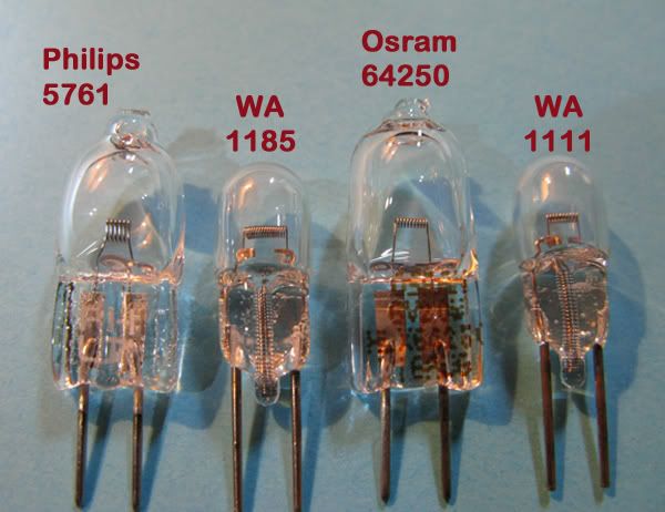
" Hot Bridge Wire " squib ignitor made from a flashlight or torch light bulb. Heating it with a
blowtorch to poke it open with a nail , and fill it with powdered match heads. The flashlight
itself is the only power supply needed and an arbitrary length of hookup wire.
Bulbs are manufactured with small values of resistance, which of course increases many fold
when turned on , limiting the working current. This complicates calculation of adding the
measured ohms of the firing cable. To determine the voltage needed to obtain the working
current its easiest to just test the bulb connected to the firing cable to light it before making
it into an ignitor. Using one more 1.5 volt battery than what is normally required should be
sufficient. Moderately higher voltage drives excessive current through the bulb lessening
it's life in normal use , but as it burns brighter that may be advantageous in this application.
http://www.bulbtown.com/1_0_2_99_Amp_Light_Bulbs_s/665.htm
http://www.bulbtown.com/1_4_9_Volt_Light_Bulbs_s/764.htm

[url][/url]

Primary ( initiating ) explosives ( substituted for match heads ) can be detonated in this same
way. http://en.wikipedia.org/wiki/Blasting_cap
Multiple charges are routinely connected by detonation cord set off from a single blasting cap.
Apart from wearing high impact resistant eyeglasses and face visor , ballistic vest , and tongs
or forceps for handling , thoughtful precaution is necessary when making an electric blasting
cap as the wire leads are effectively a dipole antenna and as such susceptible to radio frequency
broadcast in the vicinity which could resonantly induce current sufficient to heat the bridgewire
( filament in this case ). From the time it is first loaded with explosive and initially been tested
for continuity ( read the following procedure ) to the time when it will be used , the exposed
lead ends must remain twisted together. To ensure there is no hangfire , immediately prior to
use ( by having the cap inside a pit dug into the ground covered with a sand bag ) it is tested
for continuity , a tricky feat that requires a milliampere low voltage source of just under 1 volt.
The cap lead ends are then connected at this time to the cable or wire that will be used for
firing it, which is also first tested for continuity being already shorted and disconnected at the
power end. The final act is to bring the cap from under the sandbag to the main charge of
secondary explosive and inserted into a previously formed opening there , then promptly leaving
the scene to a safe area. The last thing before firing is to un-short the cable end and test again
for continuity before hooking up to power for firing . This is to distinguish an electrical failure
mode from a dud hang fire which may perhaps be still smoldering , ready to explode , in that
case a wait of 15 minutes or more is warranted before approaching the item for inspection.
For a high degree of safety one could instead electrically light a fuse first to then set off the
blasting cap. ( Individuals who snicker and think all this is excessive , are by definition kwels )

[url][/url]

__________________________


The EBW ( exploding bridge wire ) is an altogether different device that initiates detonation of
secondary explosives in direct contact without the use of primary explosives. This is accomplished
by vaporizing a small metal wire by the rapid Joule heating produced by a nearly instantaneous
( very low impedance ) applied electric current. Immediately evident by the very L O U D bang
it makes , note there will be little sound if the wire only melts and drips away much as a fuse.
( See here fusing current ) - http://www.ndrr.com/rmr_faq/Introduction/Fusing-Currents.htm
and also this - http://www.litz-wire.com/New%20PDFs/Fusing_Currents_R2.011609.pdf
* Note that both the above references omit to state that the wire diameter must be C U B E D
. before taking the square root , so , √ ( D X D X D ) , only then multiplied by the coefficient " A "

EBW devices must be within arms reach of the pulsed power source and supplied by a short
low impedance cable typically within 40 - 50 cm. This can be :
Solid copper core RG-8U Coaxial cable ,
[url][/url]

Braided or Rutherford Litzendraht ( Litz ) wire
[url][/url]

http://en.wikipedia.org/wiki/Litz_wire , http://www.litz-wire.com/applications.html ,
http://www.hmwire.com , http://www.hmwire.com/sm.html ,

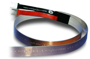
Goertz flat ribbon cable ,
[url][/url]
similar available plain and much cheaper from _ http://www.alphacoredirect.com/contents/en-us/d53.html

or 2 plys of 12AWG from http://www.decorp.com
[url][/url][url][/url]

http://www.flatwirestore.com/mm5/merchant.mvc?Screen=CTGY&Store...
http://www.tycoelectronics.com/catalog/cinf/en/c/11930/1486
http://www.tycoelectronics.com/catalog/minf/en/152
http://www.ampnetconnect.com/product_groups.asp?grp_id=1660&pat...
http://www.ampnetconnect.com/product_cut_sheet.asp?grp_id=2285&...
even 2 edgewise parallel flat cross section solid grounding strap would do.
http://www.keison.co.uk/furse/conductors_flat_tape.htm
Fralock transformer coil copper tape
http://www.surplussales.com/RF/RFSilv-CoppS.html
_____

Perversely , the uninitiated continue to believe that the bridge wire itself is a resistive element ,
- - W R O N G - -
A bridge wire is just that , an UNINSULATED wire having as low a DC current resistance as
possible. Due to the extremely short time rise of the current , initially conduction occurs only
along the surface , known as " skin effect ", as the wire heats up the resistance increases,
then as the wire melts the resistance drops again and conduction resumes now through the
entire cross section and continues to increase as it becomes vapor. High resistance material
inhibits this progression so that the surface is cooked off forming a vapor boundary layer which
is more conductive , dissipating the discharge as a heat flash , not shock.* Note this is a
principle reason why very fine wire is used in pulses of very short time frames , the current
simply cannot penetrate into the depths of the wire where it needs to be to rapidly heat the wire.


The applicable equation of state is , I = V / R , current I = amps , V = volts , R = ohms
Arithmetically R must be as small as possible to maximize the current. This is why kilovolts
are typically applied , to assure a huge current surge and rise time.

[url][/url]


Another misconception is the available energy provided to the wire.
A capacitor's stored energy according to E = CV^2 /2 , E = Joules , C = farads , V = volts
83 Joules = (.00082 F X 450 X 450 ) / 2
may be adequate to the task were it all to arrive instantaneously - which it cannot , being
a function of time and restrictive circuit characteristics. The determinant will be Power ,
the rate at which the energy can be delivered by the cable to the EBW. Because this is a
rate per second , at initial discharge apparent power seems as if megawatts are on tap.
Read Overview here _http://en.wikipedia.org/wiki/Pulsed_power
Dividing 83 Joules by the discharge time .000160 sec = 0.518 Megawatt average power
discharge time is calculated as follows : see - RC time constant , below

[url][/url]

- RC time constant
Determining the time during which the initial discharge occurs is given by
TC = RC , R = ohms , C = farads ,
TC means Time Constant , a factor which relates the rate at which the capacitor discharges.
Specifically , 63 percent of charged voltage during the first TC leaving 37 percent remaining ,
86 percent of the original after 2 X TC , leaving 13 percent of the total remaining , after the
third TC 95 percent discharge has occurred. Complete discharge is assumed after 5 X TC.
See middle of page here -
http://www.kpsec.freeuk.com/capacit.htm
also bottom of this page - http://www.bcae1.com/capacitr.htm
RC TC in depth - http://www.electronics-tutorials.ws/rc/rc_1.html
RC Time Constant Calculator - http://www.cvs1.uklinux.net/cgi-bin/calculators/time_const.cgi

Capacitors exhibit resistance which limits their rate of discharge, known as ESR ( Equivalent
Series Resistance ). Smaller ESR means a shorter RC Time Constant and more power
( energy delivered per unit time ). For the capacitor type and size range applicable typically
around 0.1 ohm or less. Reducing ESR shortens the TC and the current rise time without needing
to have higher voltage to compensate for higher resistance.
Very short pulse durations
are only acheived by capacitors having exceptionally low ESR. As these do not have large
capacitance, they must have a very high voltage to store significant energy.
What is a Capacitor ? - http://www.sofia.usra.edu/Edu/materials/activeAstronomy/sec5_capaci...
http://www.bychoice.com/capacitor_DF.pdf
http://www.illinoiscapacitor.com/uploads/papers_application/F8CD49C...
http://www.cartage.org.lb/en/themes/sciences/physics/electromagneti...
Equivalent Series Resistance (ESR) of Capacitors - http://www.low-esr.com/QT_LowESR.pdf
Equivalent Series Resistance of Tantulum Capacitors , Both the following PDF's are the same
- http://www.avx.com/docs/techinfo/eqtant.pdf
- http://www.avxtantalum.com/pdf/EQTANT.PDF

- In the opening post of this thread -> http://www.sciencemadness.org/talk/viewthread.php?tid=11756
given 820 uF or .00082 F, assuming a 2 cm 28 AWG EBW
Resistance of EBW = .004 ohm , plus Resistance of cable = .0267 ohm ( sum of core and shields
resistance of 3 meters 10 AWG RG-8U coax , see footnote ## ) , estimated ESR
0.1 ohm ( note that ESR is 3 times greater than the rest of the circuit resistance ) the total
circuit resistance = .131 ohm then TC = RC = (.131 )(.00082 ) =.000107 ~ 107 microseconds

- discharged at 450 volts after one TC the remaining voltage is 167 ( 37 % ) , so by E = CV^2/ 2
( .00082 X 167 X 167 ) / 2 = 11.5 Joules , dividing by the rating of 83 Joules ( 11.5 / 83 ) = 13.8 %
100 % - 13.8 % = 86.2 % of the energy is delivered during the first 107 microseconds. The magic
factor is 1.5 times the TC when the remaining charge is 100 volts ( 22.2 % ) 95 % of the energy
of the capacitor has gone into the line in just 160 millionths of a second. What this means is if
conduction is still occurring only along the surface of the EBW , there will be no loud B A N G !
http://www.probertencyclopaedia.com/cgi-bin/res.pl?keyword=Effectiv...

- Given that frequency is the reciprocal of time , f = 1/ t , then the 160 millionths of a second
translates to a frequency of 6.25 kHz. Well below the 170 kHz where skin effect reduces
cross sectional saturation. Look up 28 AWG , here -> http://www.powerstream.com/Wire_Size.htm
Note that this value would be a mere 2.6 kHz for the 10 AWG coaxial core were it just bare wire
instead of coaxial cable.
_____

Joules needed for vaporization of a 2 cm 28 AWG wire = ( weight of EBW / molar weight Cu ) X
( * *Enthalpy of vaporization of Copper 300 KJ / mol + Heat of fusion 13.1 KJ / mol ) =
( .0145 gm / 63.546 gm/mol ) X ( 313100 J/mol ) = 71.4 Joules
By comparison an equivalent weight of TNT yields 65.5 Joules (.0145 X 4519 Joules/gm )
* * From http://www.webelements.com/copper/thermochemistry.html
weight of bridge wire is easily obtained from this applet here _
http://circuitcalculator.com/wordpress/2007/09/20/wire-parameter-calculator

Resistance of EBW = .004 ohm , Resistance of cable = .0267 ohm ( see footnote ## )
The energy is consumed along the entire circuit's resistance. The portion which will act on
the EBW is: .004 / (.004 +.0267 ) = 0.03 , alternatively a 25 cm length of cable is .0022 ohm
recalculating , .004 / (.004 +.0022 ) = 0.645 , then .645 X 83 Joules = 53.5 Joules
An 83 Joule rated capacitor will not be adequate with inherent circuit losses , and still
be marginal with somewhat thinner wire. A thinner wire has less mass and will require less
energy to vaporize while presenting more resistance and consume a greater portion of the
available energy in the circuit. Worth a try with an aluminum foil ribbon and very short cable
run ~ 25 cm. Remember it must make a very loud bang , if it does not sound like a rifle shot
you have not achieved detonation status.
12AX7 observed in this other post
http://www.sciencemadness.org/talk/viewthread.php?tid=6032&a...
the only energy that matters in a system is that which actually achieves the intent.

_____

Capacitive reactance and Inductive reactance the two components of circuit impedance
behave as an additional form of resistance which interferes with rapid discharge of the
capacitor and transmission of that power as a short pulse. Coaxial power cable limits this
to a maximum of it's characteristic impedance of 50 ohms regardless of length. This value
is only a transmission line design parameter , whereas the actual line impedance of your
particular firing cable depends entirely on the wavelength of the discharge waveform
relative to the cables length , and what is attached on the ends. Given that wavelength
is the speed of light ' c ' divided by the frequency , λ = c / f, or alternatively multiplying
by the time of discharge , wavelength = λ = c X t = ( 300,000,000 X .00016 ) = 48000 meters.
The actual wavelength within the cable is always shorter than this because it slows down
( similar to light when it enters a denser medium ) known as " velocity propagation factor ".
For RG-8U it is 0.84 of light speed. A pulse that is lengthy due to a long discharge time
becomes shorter by the propagation delay inherent to the cable. A cable of just 3 meters
behaves here as a short circuit , exhibiting practically no line impedance to or attenuation
of the discharge pulse. See footnote below - IMPEDANCE EXPLAINED -
Xc = .159 / f C , Xc = capacitive reactance of the capacitor expressed as ohms
f = frequency , C = farads. So , Xc = .159 / ( 6250 X .00082 ) = .031 ohm ( vanishingly small )
* Note the absurdly overpriced Goertz " speaker cable " exhibits a characteristic impedance
of just 2 to 4 ohms by further reducing line induction.
Unrelated to the present topic , a rational perspective on such expensive attributes.
http://www.leedsradio.com/technical/snakeoil-cables.html


Ideally the EBW will have melted by full discharge as the current surge drives through
the lowering resistance and vaporizes the wire. We have observed that the ESR of the
capacitor is the most pronounced inhibitor of circuit performance , throttling the power
available. By the end of the next post it will be evident how the effect of ESR can be
minimized to improve the response and performance by at least two fold.


_____

The power feed cable as selected below must be of large gauge to minimize resistance
( ## 3 meter length of RG-8U coax ) or a braid of Litz cable. Welding cable can
suffice for only very short lengths but the induction becomes significant in the circuits
performance. This is because it acts as a transformer primary , magnetically coupling
with anything electrically conductive even moist ground.

Given everything going for it one can see why this has no application other than for
use in ordnance where the EBW can be snug up against the pulse generator.
A setup for outdoor use will need to have the pulse generator close by which puts it
at hazard if used to detonate explosives. Charging and firing control can be done from
a distance with a 3 wire extension cable. ( See the circuit diagrams - next post - below )

* 28 AWG is a common size used in " wire wrap " electronic board prototyping.
Click thumbnails then click again the pictures here -> http://en.wikipedia.org/wiki/Wire_wrap
My suggestion of 28 AWG is 3 to 4 times thicker than what is usually used for an EBW,
and with much bigger caps. Given that the 1 mil to 3 mil wire otherwise used is AWG 40
and smaller which is much finer than hair one should not stray too far from 28 AWG wire
as selected above. Much smaller wire size as noted requires less effort to explode but
becomes increasingly more difficult to physically work with and prepare. Larger wire
naturally requires greater energy to explode but more importantly the lower frequency
at which skin effect becomes significant will affect cross sectional current saturation.
Fine wire is cheaply obtained from ordinary stranded electric line cord. Count the number
of strands in the wire bundle of a known gauge ( 14 AWG being common ) to derive the
single strand size verified here _ http://www.interstatewire.com/WireTable.htm
http://www.seas.gwu.edu/~ecelabs/appnotes/PDF/techdat/swc.pdf

==> One experimenter's results with videos
http://members.tm.net/lapointe/Wire_Explosions.html
Viewing this setup one immediately can see despite success with fine copper wire that
such a large loop of single conductor must sap considerable energy by inductive losses.
This can't be stressed enough , the faster the current rise time , the greater the need
to minimize induction in the circuit !
Viewing the following videos I ask myself what's wrong with this picture. The widely
separated cables is what , which is in effect a single turn solenoid the induction of
which is responsible for the mediocre results observed.
Capacitor like woelen's - explosion -
http://www.youtube.com/watch?v=CY8bkf7QcVE
same guy with new General Atomics capacitor
http://www.youtube.com/watch?v=QMWRvAI4o2E
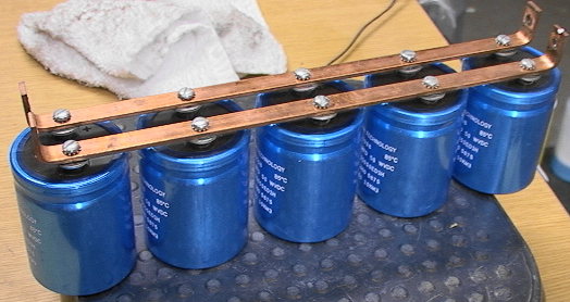
Banks of capacitors in parallel have one fatal flaw :
ALL of the energy will discharge into the capacitor that fails destroying it and
perhaps damaging those that are alongside.

[url][/url]
It's essential to design a capacitor bank so that the individual caps can have at
least one terminal disconnected from the common conductor with the other caps
so that it can be individually tested for "leakage current" and signs of impending failure.

http://www.fullnet.com/~tomg/esrscope.htm
Invest in a good RCL bridge meter that can measure this. Better yet get it all in one
package , the most prized of all , Sencore LC 75, 76, 77, 101, 102, 103 ( may be
seen on EBay for ~ 150 to 250 dollars and up ) These can even re-form deteriorated
aluminum electrolytics. The oxide insulating layer will tend to deteriorate in the absence
of a sufficient rejuvenating voltage, and eventually the capacitor will lose its ability to
withstand voltage if voltage is not applied. A capacitor to which this has happened can
often be "reformed" by connecting it to a voltage source through a resistor and allowing
the resulting current to slowly restore the oxide layer.
( See my attachment Equivalent Series Resistance & Maximum Leakage.rtf
next post below in Pulse Power - Firing circuits )

http://bama.edebris.com/download/sencore/lc102/LC102.pdf
Cheaper expedient methods (with oscilloscope ) are available
http://octopus.freeyellow.com/esr.html
http://octopus.freeyellow.com/99.html
All the way at the bottom see ' Scope ESR ' here _
http://www.anatekcorp.com/ttg/tiptrick.htm
_____

- IMPEDANCE EXPLAINED -

http://www.eskimo.com/~ddf/Theory/Char_Z.html
http://www.speedingedge.com/PDF-Files/BTS002_Characteristic_Impedan...
The activity in a 3 meter cable at the discharge frequency of 6.25 kHz being very much
less than a quarter wavelength is seen at the extreme right side of this diagram here_
http://www.tpub.com/content/neets/14182/css/14182_150.htm
http://www.allaboutcircuits.com/vol_2/chpt_14/5.html
http://www.epanorama.net/documents/wiring/cable_impedance.html , See the following
- Cables characteristics at high frequencies
- Why attenuation figures tend to increase with increasing frequency ?
Impedance calculations ( scroll down )
http://ocarc.ca/coax.htm
http://www.mantaro.com/resources/impedance_calculator.htm
http://hamradio.arc.nasa.gov/coaxcableloss.html
http://74.125.93.104/search?q=cache:xfy31beGKowJ:hamradio.arc.nasa.gov/coaxcableloss.html+%22Belden+9913%22&cd=58&hl=en&ct=c lnk&gl=us

FOOTNOTE

## 3 meter length of Belden 9913 10 AWG solid copper core RG-8U coax , .0089 ohms / meter
( sum of both core and shield resistance )
RF9913 - $ 0.76 cents ft ( recommended vendor )
- http://www.radiobooks.com/products/rf910.htm
- http://www.radiobooks.com/rwcoax.htm
25 ft cable + UHF connectors, or custom size ready made - $39.95
- http://www.radiobooks.com/products/ca9913.htm

An RG-213 stranded conductor 7 X 21 AWG + UHF connectors, ready made cable
may be suitable to sustain a multi kilojoule pulse for modest power throughput
( rated for 5 kilowatt ( 250 V X 20 amp ) due to the effective cross section being
half that of solid core RG-8U, is cheaply available here _
http://www.buckscom.com/catalog/index.php?main_page=popup_image&...
http://www.buckscom.com/catalog/index.php?main_page=product_info&am...
This one is preferable for applications at kilovolts having a very short time pulse.


Belden 9913 - 0.79 cents/foot ( alternative more expensive vendors )
http://www.theantennafarm.com/catalog/index.php?main_page=product_i...
http://www.signalpros.com/index_files/Page3071.htm
http://www.progressive-concepts.com/info/item.html?id=68
RG-8U Cable specifications and data -
http://www.contactcables.com/products/Belden/Belden9913datasheet.pd...
http://www.alliedelec.com/Images/Products/Datasheets/BM/BELDEN_WIRE...
http://sigma.octopart.com/30985/datasheet/Belden-9913-010500.pdf
http://www.belden.com/pdfs/03Belden_Master_Catalog/06Coaxial_Cables...
( page 6.70 )


Fusing current
http://www.ndrr.com/rmr_faq/Introduction/Fusing-Currents.htm
http://www.litz-wire.com/New%20PDFs/Fusing_Currents_R2.011609.pdf
http://www-d0.fnal.gov/hardware/cal/lvps_info/engineering/wirefusin...
http://www.interfacebus.com/Reference_Cable_AWG_Sizes.html
http://www.interfacebus.com/Aluminum_Wire_AWG_Size.html

Wire chart
Solid conductor
http://amasci.com/tesla/wire1.html
http://www.powerstream.com/Wire_Size.htm

Stranded conductor
http://www.interstatewire.com/WireTable.htm
http://www.seas.gwu.edu/~ecelabs/appnotes/PDF/techdat/swc.pdf

Wire calculator
http://circuitcalculator.com/wordpress/2007/09/20/wire-parameter-calculator

Unit conversion
http://www.allconversions.com


__________________________________________

Pulse Power - Firing circuits

franklyn - 22-6-2009 at 00:40

All the previous analysis presupposes the capacitor is a stand alone power source connected in a
closed loop with the EBW. Energy storage capacitors as these below, while suitable for exploding
wires , are large and unwieldy. A high voltage power supply is also needed to charge them.

240 uF 5000 Volts - 3000 Joules
http://cgi.ebay.com/ws/eBayISAPI.dll?ViewItem&item=350128516137

[url][/url]

http://www.gaep.com/capacitors.html


To provide a large power pulse , a current surge generator is a better arrangement.
By intentionally causing the a.c. power line to short circuit through the EBW , this enables
a very large power pulse to be directly applied with minimal , relatively inexpensive hardware.
In this scheme the capacitor voltage discharges through a spark gap to complete a circuit
with the a.c. power line , resulting in conduction of a huge current surge ( termed " in rush
current ") through the firing cable. This is known as '" Power OR " mode of operation , a
" shunt " diode channels this " follow current " from the a.c. line conducted by the arc.
See F O O T N O T E S bottom of the next post following
Also read here beginning the 3rd paragraph at left _
http://img11.imagevenue.com/img.php?loc=loc284&image=05761_Magnetizing_.jpg
A current surge of hundreds of amps during one half cycle of the a.c. power line
frequency can be tolerated only as a self terminated transient event to prevent damage
to the firing circuit and in particular the a.c. power line. The EBW additionally serves as
the circuit protection fuse , taking only just the power used to explode.
A 300 amp surge through a 2 cm 28 AWG wire by P = R I^2 = .004 ( 300 X 300 ) = 360 watts ,
more than 5 times what was determined necessary to be vaporized. Note that much more
power is consumed by the rest of the power line circuit which heats up considerably though
manageably in a single shot event. Line transients as these are commonly handled by
commercial surge suppressors discussed here - http://www.zerosurge.com/PDF/PQ94.pdf

_____

Drawing ' A ' ( attachment ) restricts the capacitor current to only the firing circuit by having
the capacitor ' C ' parallel with the a.c. line. Synchronizing a.c. line commutation to occur
in phase with the capacitive discharge is facilitated by a triggered spark gap or gas tube ' gg '
as part of the capacitor EBW circuit - Drawing ' B '
See footnote - Triggered Switches , in the post following this one and
- http://www.angelfire.com/80s/sixmhz/trigatron.html
This allows the peak voltage of the a.c. line to trigger the gas gap into conduction.
A diode ' d ', restricts triggering to the phase when the a.c. line voltage has
the same polarity as the caps. This arrangement does not receive the power boost
provided by having the capacitors in series with the a.c. line and will not be considered further.
3 terminal gas tube - 2 to be used in parallel & need to have leads thickened - $ 3.02 each
- http://www.mouser.com/Search/Refine.aspx?Keyword=871-B88069X8440B20...
- http://www.epcos.com/inf/100/ds/t81a90xx8440b202.pdf

Drawing ' C ' shows the capacitor ' C ' in series with the EBW and the a.c. power line. The
problem of a.c. commutation synchronization is solved by a spark gap ' G ' which conducts
in phase at peak a.c. power line voltage. Having the a.c. power line in series with the
capacitor has an additional benefit that the a.c. line voltage and capacitor voltage add
together increasing the voltage to the EBW , improving the current rise time. A large
diode ' D ' provides a path for the resulting current surge generated in the firing circuit.

_____

* * * Note that all the following circuits are divided into a charging and switching part shown
on the left side of each drawing , and the power storage part shown on the right side of the
same drawing. The entire circuit is interconnected across some distance with a 3 conductor
cable serving as an extension cord. Each conductor is labeled
' Top ' , ' Mid ' , ' Bot ' ( Top , Middle , Bottom )
This arrangement also charges the extension cable to the same static voltage as the capacitors.
which adds the cable's capacitance to the firing circuit , reducing the damping at discharge.
' Top ' and ' Mid ' conductors flow electron current to the left.
' Bot ' conductor flows current to the right.
( This is true for all these circuits , although charging phases may have different current paths. )

Suitable cable is of the type used for connecting RV ( Recreational Vehicles )
and trailers to the electric utility main grid , RV 30 Amp Generator Cord , 10/3
( The leading number is the gauge AWG followed by the number of conductors )
Characteristic impedance for twisted pair of this type would be somewhere 100 to 200 ohms
See http://www.mantaro.com/resources/impedance_calculator.htm
Conductor inductance calculations ( nice to know not really all that useful here )
http://www.kolb-net.de/pulsedpower.html - - scroll down
A very good price is less than a dollar a foot. 500 foot loop circuit resistance = .509 ohm
http://wesbellwireandcable.com/PortableCord.html
http://wesbellwireandcable.com/SOOW/SOOW10-3.html - 250 ft - $ 247.50
http://www.americord.com/bulk-cable/prod_537.html - 250 ft - $ 217.50
Cord Nomenclature
http://www.americord.com/glossary
http://www.cables.com.tw/yuefeng/glossary.htm

Crimped and soldered terminal lugs with screws are to be used to hook up the
3 conductor connecting cable.

Plugs and receptacles to connect the charging and switching circuit to the a.c line.
http://en.wikipedia.org/wiki/IEC_connector , IEC 320 C19 / C20 , cords are not available
ready made in 30 amp rating, but can certainly be wired with 10 AWG wire and provide a
secure connection , the pins are robust enough and provide better moisture seal.
[url][url]
The following rewireable plug must have the 2 piece mating seam sealed with epoxy
http://www.mouser.com/Search/Refine.aspx?Keyword=4789.1200
http://www.schurterinc.com/pdf/english/typ_4789.pdf
http://www.mouser.com/Search/Refine.aspx?Keyword=4797.0015
http://www.schurterinc.com/pdf/english/typ_4797.pdf
http://www.apcmedia.com/salestools/SADE-5TNRML_R0_EN.pdf
http://www.feller-at.com/English/Feller-GP-E.htm
NEMA Standard connectors ( If you must , use these , but are comparatively very large )
http://www.hubbellcatalog.com/wiring/catalogpages/section-b.pdf
see B-17 to B-19

_____

Drawing ' D ' shows a practical circuit having the minimum components.
Single Pole Single Throw / NO ( normally open ) switch ' S ' connects power to charge
the capacitor(s) ' C '. Electron current flows through resistance ' R ', and parallel
resistor ' r ' with series ' LED ' light emitting diode , through diode ' dx ' and
' Mid ' conductor , collecting in the negative ( - ) terminal of the the capacitor(s) ' C ',
displacing current out of the positive ( + ) terminal flowing back through ' Top ' conductor
and shunt diode ' D ' to the a.c. source. As it is charged , light emitting diode ' LED '
momentarily flickers on then darkens indicating that charging has occurred. Resistance ' R '
is to protect the small diode ' dx ' from excessive current when charging starts ).


* * * For added safety a 10 amp fast acting circuit breaker ' X ' provides redundant
protection for domestic wiring , serving also as a switch it now does the actual firing
when turned on. The charging circuit is F I R S T switched off by normally open switch ' S '
before the charged circuit can be fired.

Circuit breaker ' X ' fires the circuit by applying the a.c. line voltage in series with the cap(s) ,
effectively doubling the circuit voltage which arcs into conduction the Gas Gap arrestor ' gg '
near the peak of the a.c. sine wave. ' Top ' conductor channels the resulting current surge
left and down shunt diode ' D ' to the a.c. source.
In practice the 325 volt peak is minimal and very marginal to produce an arc across a spark gap ,
better is a " Gas Gap Arrestor " ( use 2 or even 3 in parallel and solder thicker leads on each )
' gg ' - Gas Gap Arrestor - 444-GT-230L - $ 3.09
http://www.mouser.com/Search/Refine.aspx?Keyword=444-GT-230L
http://www.mouser.com/catalog/specsheets/XC-600002.pdf
' gg ' - Gas Gap Arrestor - (RMO) CG2-230L , middle of this page - $ 2.75
http://www.surplussales.com/Semiconductors/SemiCTransSup.html
[url][/url]
http://sigma.octopart.com/510848/datasheet/Littelfuse-CG2230L.pdf
http://octopart.com/search?q=CG2-230L , cheapest at Mouser
http://www.mouser.com/Search/Refine.aspx?N=254139&Keyword=CG2-2... - $ 1.89
' X ' - Single Pole circuit breaker - $ 10.99
http://www.mouser.com/Search/Refine.aspx?Keyword=845-1BU10R
http://www.altechcorp.com/PDFS/R-Series.pdf
http://www.mouser.com/catalog/637/1795.pdf
- @ $2 each set of 3 breakers held by pins this has two 15 amp breakers which can work
and is cheap enough to try out but needs to be dismantled
http://www.sciplus.com/singleItem.cfm/terms/348
[url][/url]
' S ' - Switch SPST / no - (SWP) 1175 , lower third this page - $ 3.75
http://www.surplussales.com/Switches/SWPushB-1.html
[url][/url][url][/url]
' R ' - 30 ohm 5% 15W Power Resistors - $ 0.63 cents X 8 resistors
( 2 sets of 4 are to be wired in series for a total equivalent resistance of 15 ohms )
http://www.mouser.com/Search/Refine.aspx?Keyword=280-CR15-30-RC
http://www.mouser.com/catalog/specsheets/XC-600041.pdf
' r ' - 8.2 kohm 5% 1/4W - $ 0.22 cents
http://www.mouser.com/Search/Refine.aspx?Keyword=30BJ250-8.2K
' LED ' - Green LED - $ 0.26 cents
http://www.mouser.com/Search/Refine.aspx?Keyword=351-5502-RC
' LED ' - Green LED - (SDI) LTL-4233 - $ 0.15 cents
http://www.surplussales.com/Bulbs-Incan-Panel/LEDDisplay.html
_____

Available capacitors that have a higher working voltage than the ~ 162 Volt peak
that comes from the wall socket , require this voltage to be stepped up.

Drawing ' E ' has the capacitor charged to a higher voltage with a transformer included in the circuit.
Switch ' S ' flows electron current through diode ' dy ' into primary coil ' p ' of transformer ' T ' and
' Bot ' conductor back to the a.c. source , inducing a current in secondary coil ' s ' of transformer ' T '.
Current flows through diode ' dx ' into ,' Mid ' conductor collecting in the negative ( - ) terminal of
capacitors(s) ' C ' charging the elevated voltage , displacing current out of the positive ( + ) terminal
flowing back through ' Top ' conductor down resistor ' R ', and parallel resistor' r ' with series light
emitting diode ' LED ', into 'secondary coil ' s ' of transformer ' T '.
( * * where the wire crosses ' Mid ' conductor there is N O connection )
Light emitting diode ' LED ' momentarily flickers on then darkens indicating that charging has occurred.
Firing as already explained is done by circuit breaker ' X ' with the charging circuit F I R S T
switched off by normally open switch ' S ' before the charged circuit can be fired.
.

_____

Alternatively as explained in Drawing ' F ' using another capacitor as a half wave
voltage doubler , ramps up the charging voltage to 2 times the a.c. line voltage.
In phase - 1 - the capacitor is charged , then in phase - 2 - the reverse voltage
of the a.c.line and the just charged capacitor add together in series aiding effectively doubling.
Illustrated here _
http://www.gallawa.com/microtech/doubler.html

Motor ' start ' capacitors are bipolar electrolytics , also called Non-Polarised or NP capacitors
and are the most suitable for use in voltage doubling as they are designed for a.c. operation ,
but only if run briefly. Those with a Voltage rating higher than the ~ 125 VAC minimally necessary
can be run for just a little longer before overheating ( over 85ยบ C , impairment will occur )
(Cy) ' 270-324 uF, 250 VAC ( the range specifies plus or minus 10% variance from 300 uF )
http://cgi.ebay.com/ws/eBayISAPI.dll?ViewItem&item=200326166634
http://www.amazon.com/dp/B000LERFO4 , ( the point here is shop around )
These here are perfectly adequate _
http://cgi.ebay.com/ws/eBayISAPI.dll?ViewItem&item=230281260691 - $ 4 each
http://cgi.ebay.com/ws/eBayISAPI.dll?ViewItem&item=370198861276
Motor ' run ' caps can operate continuously but have much less capacitance, or are
much more expensive for equivalent capacitance, and larger.
http://cgi.ebay.com/ws/eBayISAPI.dll?ViewItem&item=310028799378 - $ 12 each
Capacitor testing - http://toad.net/~jsmeenen/capacitor.html


U.S. a.c. power lines typically achieve a peak of ~ 162 volts which provides
the equivalent of 115 volts direct current, called R.M.S. ( root mean square ).
You may wonder why a.c. capacitors have the seemingly odd rating of 125 volts.
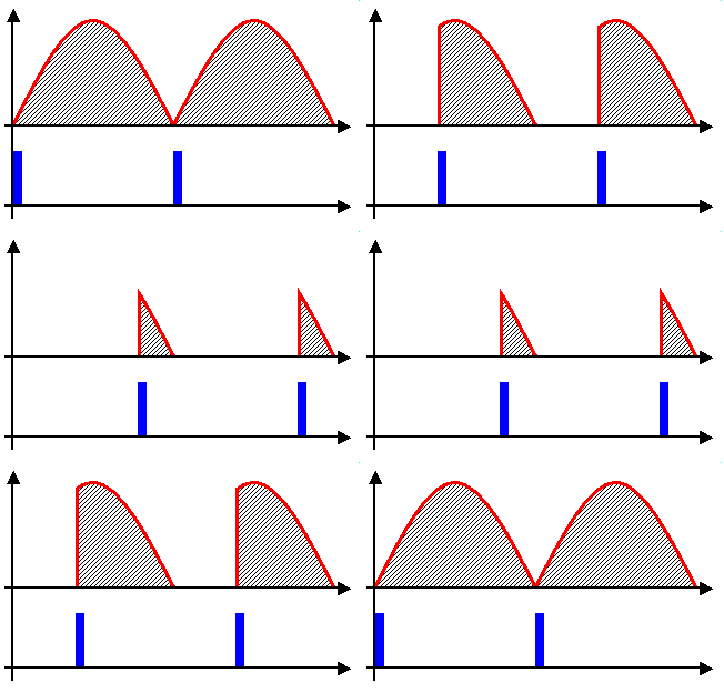
60 cycle a.c. is 120 half cycles of alternating polarity, voltage rises from zero
to peak voltage after 1/240 of a second (.004167) ( yellow portion shown below )
and over the next 1/240 of a second drops back to zero again ( green portion )
repeating this rise and fall but in reverse polarity for the following half cycle.
( orange and lime )
[url][/url]

This sets the time available for the percentage of the supplied line voltage a
capacitor will charge up to during the rise of one half cycle. It is not instantaneous.
Re-arranging the folrmula : Xc = .159 / f C , C = farads
f = frequency , Xc = capacitive reactance of the capacitor expressed as ohms ,
thus : XcC = .159 / f , = .159 / 60 , = .00265 , which is effectively the minimum
RC time constant ( TC ) for any capacitor at this frequency ( without considering
additionally the ESR which will make the time constant longer ) It does not matter
what size capacitor or what voltage is applied to it, this value is set in stone, it
is characteristic of 60 cycle a.c. and cannot be changed. Dividing the rise time
.004167 by .00265 , = 1.57 TC ( Time constants ) works out to 79 percent of
peak a.c. line voltage , or 128 volts. This in practice will never be seen due
to the resistance present in the capacitor, this despite that the capacitor will
still be charging slightly even as the a.c. line voltage is dropping , until both are
equal. As the applied a.c. voltage decreases the capacitor will discharge through
the a.c. source. The capacitor will not be completely discharged when the a.c.
line voltage reverses polarity, but as the polarity is now the same as the capacitor
polarity, the voltages aid, quickly discharging the capacitor the rest of the way.
When the applied a.c voltage reverses direction, the capacitor is charged again,
and the entire process is repeated with the next half cycle of the a.c. waveform.
The waveform of an applied sinusoidal a.c.voltage will remain unchanged and only
its amplitude ( peak value ) will be affected. Hence when measuring the voltage
pole to pole on a capacitor in series with an a.c. line you detect a voltage drop,
just as though it were a resistor, this is the capacitive reactance.
http://www.electronics-tutorials.ws/capacitor/cap_8.html

In a half wave voltage doubler , diodes are used to block one phase of the
a.c. waveform so that the capacitor remains charged when the polarity is
reversed. When the polarity again changes , charging continues where it left
off incrementally raising the voltage charged in the capacitor ever closer to
the a.c. supply voltage.

_____

Drawing ' G ' shows this scheme.
- In the first a.c. phase
current flows up from ' Bot ' conductor through resistor ' R ', and parallel resistor ' r '
with series ' LED ' light emitting diode , to motor start capacitor ' Cy ' , diode ' dy ', and
switch ' S ' back to the a.c. source. ( Resistance ' R ' is necessary to protect the
small diodes ' dx , dy , dz ' from excessive current when charging starts ).
- In the next a.c. phase
switch ' S ' flows current through diode ' dx ' , into ' Mid ' conductor,
collecting in the negative ( - ) terminal of capacitor(s) ' C ', displacing current out of
the positive ( + ) terminal flowing through ' Top ' conductor , and down diode ' dz '
( * * NOTE where the wire crosses ' Mid ' conductor there is N O connection )
into motor start capacitor ' Cy ' where the a.c. line voltage acts in series aiding , to
raise the charging voltage on capacitor(s) ' C ' to double a.c. line voltage. As it is
charged , light emitting diode ' LED ' momentarily flickers on then darkens indicating
that charging has occurred. Firing is as before done by circuit breaker ' X ' and switch ' S '
turned off F I R S T before the charged circuit can be fired.

When fired , the a.c. line voltage applied in series aiding effectively raises the circuit
voltage to 3 times the a.c. line voltage , enough for spark gap ' G ' to arc into
conduction , current surges into the positive ( + ) terminals of cap(s) ' C ' displacing
current from the negative ( - ) terminals of capacitor(s) ' C ' left through
' Mid ' conductor and circuit breaker ' X '. ' Top ' conductor channels the
current surge left and down shunt diode ' D ' to the a.c. source.

' dx , dy , dz ' - Small ~ 6 amp diodes - (SDI) MR756 - $ 0.30 cents
( 2 of these are to be wired in parallel for each of ' dx , dy , dz ' a total of 6 diodes )
found down a bit from the top , use the " find on this page " function of your browser
http://www.surplussales.com/Semiconductors/Diodes-Rectifiers-5.html
' G ' - Air Gap - 350 to 600 volts - (RMO) WP438 - near the bottom of this page - $ 3
http://www.surplussales.com/Semiconductors/SemiCTransSup.html
[url][/url]
Using Rectifiers In Voltage Multiplier Circuits
http://www.eettaiwan.com/ARTICLES/2001JUN/2001JUN14_AMD_AN2009.PDF

_____

Drawing ' H ' Omitted for clarity but an essential part of any
such devices is a means for safely discharging the stored energy of a bank of capacitors.
This must be attached and operable before the capacitors are ever charged . Under no
circumstances E V E R handle any part of these devices when charged except to fire !
Until after you have completed the ritual described in the next 2 paragraphs the circuit must
be considered to be charged even if it has been fired - there may still be residual charge.


Attached to ' Top ' conductor parallel with the shunt diode ' D ' is a 2 meter length of wire
with it's other end soldered to a strip of metal on one edge of a small wood block ' B '.
On the opposite edge of wood block ' B ' is another strip of metal soldered with a wire that's
hooked to one terminal of an otherwise unconnected a.c. plug ' E ' ( kept safely inside of
a glass jar ) this will be inserted instead of the power cord into the surge generator.
Wood block ' B ' is to be weighed and submerged in a small bucket of water acidified with
a supermarket bought pint bottle of lime juice ( citric acid ). This water " resistor " will harmlessly
dissipate the charge.

To discharge by using this circuit instead , the entire device must F I R S T be powered off
by disconnecting from the a.c. line altogether and instead connected to plug ' E '
Switch On circuit breaker ' X ' to conduct the charge through the corresponding
terminal of the a.c. plug into the receptacle wired to the water bucket.

This above is simply a very cheaply implemented expedient contrivance to obviate
more elaborate alternative permanent wiring to the circuit which will be outlined
in the closing post. A circuit can include instead a compact drain resistor network.
Wire wound power resistors can withstand Intermittent loading 10 times their rated
power for short pulse durations provided duty cycle limitations are observed. The
best compact size and price per watt is for wire wound cement types in 15 or 25
watt rating.
Remember that 95 % of the energy will dump during the first 1.5 RC time constant.
The reciprocal of capacitance 1/C is the resistance value for an RC time constant
of one second. This means that 95 % discharge of energy will occur in 1.5 seconds.
To provide an equivalent resistance that gives a discharge time long enough to stay
within the power handling capabilities of the resistor network first calculate capacitor
bank energy. An example using 6000 uF charged at 450 volts , E = CV^2/ 2 = 607 Joules
= ( .006 X 450 X 450 ) / 2 . Divide 607 Joules by the maximum excess loading factor
10 , to obtain the combined watt rating of the resistors to be used. 60.7 is most
closely 4 X 15 watt resistors. Now divide " 10 " by the capacitance thus 10/.006 ,
to give a value of 1667 ohms ( 1600 nearest manufactured value ).
Alternatively , r.m.s. discharge voltage (.707 X 450 ) is 318. Using P = V^2/ R
re-arranging to R = V^2/ P , ( 318 X 318 )/60.7 = 1666 ohm , same thing
* Dividing V^2 by full value , 607 Joules , resistance is 167 ohm same as with 1/C .
1600 ohms will discharge 95 % in 15 seconds , total discharge after 50 seconds,
why it is advisable to overload the resistors and use much less ressitance value,
by choosing instead to divide 1.5 or 2 by the capacitance .
A series of 4 groups , each with 4 resistors in parallel , 16 total ,
costing from $ 9.12 to $ 15.84 - See Mouser catalog link below _
can be secured on both sides of a thin aluminum plate ( If all resistors are the
same value then that value will be the equivalent combined resistance ) and
will give adequate heat sinking 10 times the actual 240 or 400 watt rating.
Using P = V^2/ R ( 318 X 318 )/62 = 1631 watts , what a hair blower/dryer
consumes per second. Choosing a 62 Ohm resistor , one group of 4 in parallel can
serve double purpose as the current limiting resistance for the charging circuit.
http://www.mouser.com/Search/Refine.aspx?N=4141191+4294966099+42945...
http://www.mouser.com/catalog/specsheets/XC-600041.pdf

_____

Aluminum electrolytic capacitors provide the highest energy pulse for their size.
Capacitance and voltage vary inversely , you will find those sizes having optimal
energy storage occurs at a few thousand uF at a few hundred volts. Select one
specifically designed for Strobe and Photoflash applications, these are made with
very low ESR ( Equivalent Series Resistance ). Larger capacitance has lower ESR ,
in the range of interest typically around 0.1 ohm or less. This type can best
provide the firing pulse. Price and sizes vary greatly, shop around.
http://cgi.ebay.com/ws/eBayISAPI.dll?ViewItem&item=260350709930 - 2 X $ 35
This one here is 150 Joules in 100 cc ~ ( 40 X 80 mm )
' C ' - Electrolytic Power Capacitor - 1500 uf 450 VDC - $ 5 , salvaged
* * Marx Generator made up of 10 of these = 1500 Joules
http://cgi.ebay.com/ws/eBayISAPI.dll?ViewItem&item=140322028747
* Note if this auction has ended, scroll down to the original offer and
. . select " View seller's other items ". This offer is regularly repeated.
Observe dummy terminal pinout-code VRD pg 13(pdf) , guidelines pg 19 , 20 , 21, (pdf)
http://www.chemi-con.co.jp/e/catalog/pdf/al-e/al-all-e1001i-090126....
available new from United Chemi-Con Caps - http://www.ucccaps.com
http://www.ucccaps.com/detail.aspx?ID=103647
http://www.ucccaps.com/detail.aspx?ID=105567
Described as " snap mount " usually implies " spade " type terminals for mounting
with spade wire lugs for easy replacement when servicing appliances. These
are not that kind and are best mounted on a board with terminals soldered.
- As we shall see , output of these caps can be doubled to 300 Joules per 100 cc.
_____

Hi Energy Cap
http://www.gaep.com/tech-bulletins/large-high-energy-density-capaci...
Electrolytic Technology & Design
http://www.elna-america.com/tech_al_principles.php
Aluminum Electrolytic Application Guide
http://www.cde.com/catalogs/AEappGUIDE.pdf
Electrolytic Capacitors - Testing, Care & Storage
http://www.jammaboards.com/guides/Capacitor_Testing.pdf
also online here - http://www.repairfaq.org/sam/captest.htm
ESR
http://www.gaep.com/tech-bulletins/capacitor-engineering-bulletins....
http://www.faradnet.com/deeley/book_toc.htm
Capacitor Service Life
http://www.liebert.com/common/ViewDocument.aspx?id=1210

These electrolytics are polar and cannot stand reverse bias , but can be discharged while
connected in series aiding , providing there is a diode ' D ' parallel , serving to prevent
reverse charging as described before. This is the most expensive item of the circuit selling
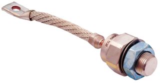
for 30 to 55 dollars U.S. A 600 volt 300 amp ( or better ) chassis mount stud type Diode
with flag terminal. one of this -> ' D ' Stud Diode - ( 300 amp - 600 volt ) - $ 30.44
http://www.mouser.com/Search/Refine.aspx?Keyword=844-300UR60A
http://www.vishay.com/docs/93508/93508300.pdf
http://sigma.octopart.com/12038/datasheet/Vishay-300UR60A.pdf, similar to these
[url][/url][url][/url]
A diode of lesser current rating ( and therefore cheaper ) can withstand
brief surges , but it won't last for very long through repeated firings of this type.
Alternatively several cheaper lesser rated diodes may be used in parallel , for example ,
4 of these -> ' D ' Stud Diode (SDI) 70HF40 - ( 70 amp, 400 volt ) - $ 0.50 cents salvaged
for anything higher than it's 400 volt rating , 2 in series 4 times , 8 total.
look down near the bottom , use the " find on this page " function of your browser
http://www.surplussales.com/Semiconductors/Diodes-Rectifiers-3.html
http://sigma.octopart.com/511589/datasheet/Vishay-70HF40.pdf
or 3 of these -> ' D ' Stud Diode - ( 95 amp - 800 volt ) - $ 6.82
http://www.mouser.com/Search/Refine.aspx?Keyword=844-95PF80
http://www.vishay.com/docs/93532/93532.pdf
General information on diodes.
http://www.kilowattclassroom.com/Archive/DiodeRec.pdf
_____

The seller of the 1500 uF cap listed above , correctly observes that 10 of those
arranged into a Marx generator , ( a device to charge caps in parallel and then discharge
them together in series ) will produce a 4500 volt output ( 450 volts each, times 10 ) but
at only 150 uF equivalent capacitance ( 1500 uF / 10 ) for a total 1500 Joules.
http://www.allaboutcircuits.com/vol_1/chpt_13/4.html
http://home.earthlink.net/%7Ejimlux/hv/marx.htm
http://www.kronjaeger.com/hv/hv/src/marx/index.html
http://www.electricstuff.co.uk/marxgen.htm
Greinacher Cascade Multiplier _
http://www.instructables.com/id/High_Voltage_Power_Supply_For_Marx_...
see parts (CFP) YE-TW-3 and (CFP) YE-TW-6 , here _
http://www.surplussales.com/Capacitors/motorstart.html
http://www.techlib.com/files/voltmult.pdf
http://www.amazing1.com/download/MARXIU1045.pdf
http://www.celnav.de/hv/hv3.htm
http://www.celnav.de/hv/hv4.htm
Here is a real big one ->http://skyfi.org.ru/photos/2008/marksgen/005.jpg
http://skyfi.org.ru/photos/?path=marksgen


Drawing ' I ' shows this with just 4 caps , gaps and diodes in place of resistors,
( anyone of the already outlined charging circuits can be used here )
switch ' S ' flows current through resistance ' R ', and parallel resistor ' r '
with series light emitting diode ' LED ', up diode ' dx ', into ' Mid ' conductor,
through diodes ' d1 ' collecting in the negative ( - ) terminals of capacitors ' C ',
displacing current out of the positive ( + ) terminals flowing through diodes ' d2 '
and out diodes ' dy , dz ' into ' Bot ' conductor back to the a.c. source.
( one 600 volt diode as ' dx , dy ' in line , per every 3 capacitors to resist reverse breakdown
during firing if caps are charged at just a.c line voltage , add more diodes as needed if caps are
charged at higher voltage and substitute spark gaps for the gas gaps ).
As it is charged , light emitting diode ' LED ' momentarily flickers on then darkens
indicating that charging has occurred ( this is also necessary to protect the small diodes
from excessive current when charging starts ). The charging circuit is to be switched off
F I R S T before the charged circuit can be fired. A normally open switch
accomplishes that.

Circuit breaker ' X ' fires the circuit by applying the a.c. line voltage in series with
the caps ' C '. Current is drawn back through ' Mid ' conductor from the
negative ( - ) terminal of the left cap ' C ' which arcs into conduction the left Gas Gap ' gg ' ,
in an avalanche cascade , current surges from the negative ( - ) terminals of all caps
' C ' across Gas Gaps ' gg ' into the positive ( + ) terminals of cap(s) ' C '
to arc into conduction Spark Gap ' G ' where from current surges into the positive ( + )
terminal of the right cap ' C '. ' Top ' conductor channels the resulting current surge
to the a.c. source down shunt diodes ' D1 , D2 ' in series to resist reverse brealdown
during firing.

______

Given the example of the 1500 uF 450 Volt cap , it can be charged at 3 times the
peak domestic U.S. a.c. value of 162 volts (* 115 volts X √2 ) to 486 volts ( note
that overcharging slightly ~ 8.5 % is perfectly alright providing it is discharged
promptly and since it is static and not subjected to cyclical deep discharge at
a.c. line frequency which will cause overheating and breakdown failure ).
Voltage of the ten caps ( 10 X 486 ) + 162 peak a.c. line voltage add to 5022 volts
By E = CV^2/ 2 , E = Joules , C = farads , V = volts
1891 Joules = (.00015 F X 5022 X 5022 ) / 2 , , or as Dirty Harry ( Clint Eastwood ) would say
- " will blow your head clean off " - , this is not an exaggeration , 1891 Joules is equivalent to
1395 foot pounds of muzzle energy , a proof load for the .44 caliber remington magnum ,
and nearly the equal of the large heavy power cap shown above.
Loud blowing up of fruit http://www.youtube.com/watch?v=aWf-V2-kr9Q
Here is what happens with 9 kJ - equivalent to a .50 caliber Browning Machine Gun round.
from http://www.powerlabs.org
Just think , that could be you all over the street.


9kJ is what a hair blower/dryer consumes in only six seconds The short time interval
of the pulse makes all the difference. Read Overview here _
http://en.wikipedia.org/wiki/Pulsed_power

- This is continued in the following post -

___________________________________________


Entire Series.GIF - 35kB

- continued from the post above -

franklyn - 22-6-2009 at 00:43

If 2 capacitors ' C ' are placed in a circuit so that both are in series , as in the
Marx layout , equivalent capacitance then becomes 750 uF , but the voltages in series
add 486 + 486 , plus the a.c. power line voltage of 162 peak comes to 1134 volts at firing.
By E = CV^2/ 2 , (.00075 F X 1134 X 1134 ) / 2 , = 482 Joules

Drawing ' J ' - T H I S . I S . T H E . O N E . T H A T . M A T T E R S
Alternatively if both capacitors are placed instead in parallel as in circuit Drawing ' J ' , the
equivalent capacitance is the sum of both , 3000 uF. The firing voltage remains the
same , charged to 486 volts ( 3 times peak a.c. line voltage ) plus the a.c. power line
voltage boost at firing comes to 648 volts.
By E = CV^2/ 2 , (.003 F X 648 X 648 ) / 2 , = 630 Joules

THE LESS ELABORATE CIRCUIT OUTPUTS . 1 4 8 . JOULES MORE POWER !

Employing the higher voltage rated caps ~ 450 volts requires a voltage tripler circuit
and an additional charging a.c. motor start capacitor. This is outlined in Drawing' J '
Single Pole Single Throw switch - SPST / no ( normally open ) ' S ' connects the
charging circuit of a.c. motor start capacitors ' Cx , Cy ' & diodes ' dx , dy '.
( * * NOTE where the wires cross ' in between ' Cx , Cy ' there is N O connection ).
Half cycle ' 1 ' charges the caps and half cycle ' 2 ' applies both voltages in series with
the a.c power line voltage to diodes ' d1 , d2 ' and the firing capacitors ' C '
charging them in parallel to 3 times the a.c. voltage. Electron current flows through diode
' d1 ' into ' Mid ' conductor collecting in the negative ( - ) terminals of caps ' C '
displacing current out of the positive ( + ) terminals flowing through ' Top ' conductor
and down into diode ' d2 ' ( * * NOTE where the wire crosses ' Mid ' conductor
there is N O connection ).
Resistance ' R ', is necessary to protect the small diodes from excessive current
when charging starts. Parallel with ' R ' is an a.c. voltage rated light bulb ' B ' to
provide visual indication when it momentarily flickers on then darkens indicating that charging
has occurred. Firing as before is done by circuit breaker ' X ' with switch ' S '
turned off F I R S T before the charged circuit can be fired.
Circuit breaker ' X ' fires the circuit by applying the a.c. line voltage in series with the cap(s) ,
which arcs into conduction the Spark Gap ' G ' near the peak of the a.c. sine wave.
' Top ' conductor channels the resulting current surge left and down shunt diode ' D '
to the a.c. source.


I want to emphasize that it is possible to achieve equally high energy and
power surge levels using fewer components than for the Marx generator mentioned above.
Compared to the 1891 Joule Marx generator of 10 - 1500 uF caps ,
just 6 of these caps in parallel as in Drawing ' J ' would be 9000 uF , then By E = CV^2/ 2 ,
1890 Joules = (.009 F X 648 X 648 ) / 2

EQUIVALENT OUTPUT OF JOULES USING FEWER COMPONENTS !
The circuit performance is improved by eliminating the extra resistance that is present
with the extra components and wiring. By having a bank of capacitors in parallel , just as
with resistors in parallel , equivalent resistance is greatly diminished , ( the exact opposite
of series resistance
! ).
http://www.electronics-tutorials.ws/resistor/res_4.html
http://www.electronics-tutorials.ws/capacitor/cap_6.html
http://www.electronics-tutorials.ws/capacitor/cap_7.html
The same as with batteries , for capacitors in series the voltages add , for capacitors in parallel
the currents add. The RC time constant remains unchanged for either configuration because the
ESR of individual caps does not change. TC = R X C = ( 0.1 X .0015 F ) = .00015 sec

- | - For six 1500 uF caps in series the errected capacitance is ( 1500 / 6 ) = 250 uF, the ESR
value of each adds so that 6 X 0.1 ohm = 0.6 ohm , TC = R X C = ( 0.6 X .00025 F ) = .00015 sec.
- | - For six 1500 uF caps in parallel capacitance adds totaling ( 1500 X 6 ) = 9000 uF, equivalent
ESR of the bank reduces to ( 0.1 ohm / 6 ) = .0167 ohm , TC = ( .0167 X .009 F ) = .00015 sec. also

By graphing power relative to time as it appears on an oscilloscope, energy is represented by
the area under the power trace. Capacitor ESR establishes how brief the RC time constant is
and how narrow the pulse. By varying the voltage , the only thing that can be altered is the
leading slope of the pulse ( and the height ) not its width ( the area remains constant because
the energy is the same ) Very short pulse durations are only acheived by capacitors having
exceptionally low ESR. As these do not have large capacitance, they must have a very high
voltage to store significant energy.The increased resistance of the series circuit depletes more
power and is less efficient. More importantly with lower voltage one can dispense with heavy
high voltage insulation requirements to obviate systemic breakdown ( arcing ) which occurs at
kilovolt levels. At kilovolts everything is huge
http://www.celnav.de/hv/hv1.htm
Of course lower voltage produces comparatively longer current rise time ( all things being
equal ) but it won't matter given the following current surge.


The rated energy per cap at 450 volts is 150 Joules times ten caps is 1500 Joules.
By slightly overcharging to 486 volts plus the boost from a.c. line voltage applied in series
during it's discharge , output is increased to 3149 Joules = (.015 F X 648 X 648 ) / 2
slightly more than the 165 pound 240 uF high voltage capacitor mentioned at the beginning
of this post. Yet this device is small enough to fit into a shoe box and weigh less than a
3 liter bottle of soda.
How to size a capacitor bank , specific for ultracapacitors but generally applicable.
http://www.powerdesignindia.co.in/STATIC/PDF/200807/PDIOL_2008JUL31...
See attachment below - Equivalent Series Resistance & Maximum Leakage.rtf -

One can determine all the values for one capacitor and then simply
- - multiply by the number of caps to obtain the output of all. Thus:
By E = CV^2/ 2 , (.0015 F X 648 X 648 ) / 2 = 315 Joules
- - 315 X 6 = 1890 Joules
ESR of one 0.0015 Farad cap is ~ 0.1 ohm R in value
TC ( Time Constant ) by R X C = TC , 0.1 X .0015 = .00015 sec
Average power of a single cap is ( 315 joules / .00015 ) = 2,100,000 watts
- - times 6 ( caps ) is 12.6 megawatts combined average power.
Mean voltage is close to the RMS ( Root Mean Square ) value
( Peak voltage is ~ 648 ) X 0.707 = 458 volts
Dividing 2,100,000 watts by 458 volts = 4585 amps average current
- - 4585 X 6 caps = 27510 amps.

A related thread on this topic http://www.sciencemadness.org/talk/viewthread.php?tid=6032
Pulsed power has many varied applications. http://www.nessengr.com/links.html
A pulse can serve to energize a laser, or a maser ( its equivalent in the microwave region ).
Jolt a coil generating intense magnetic flux or provide the feed current to a magnetic flux
compression generator. This remains an area of endeavor into high energy physics within
the means of shoe string budgets.
http://en.wikipedia.org/wiki/Explosively_pumped_flux_compression_generator
Coin shrinking - http://205.243.100.155/photos/shrinker5.pdf
applying the data just derived above on a 20 turn coil of 1/2 inch ( 12.5 mm )
using flat tape conductor as this _
http://www.keison.co.uk/furse/conductors_flat_tape.htm
The more squat the coil the higher the induction
Flux Density (in Gauss ) = N I / (2.02 ร— L)
Where:
N = # of turns of wire on coil
I = current flowing in coil ( Amperes )
L = length of coil ( Inches )

Flux Density (in Gauss ) = ( 20 )( 27510 A ) / (2.02 ร— 0.5โ€) = 54.5 Teslas
54.5 times the 10,000 gauss a Neodymium magnet has in a closed armature , which is
5 times what the 2000 gauss open air or gap flux will be , 272 times more. In other
words, the field of a rectangle of Neodymium magnets 16 by 17, 272 total, compressed
into the space of one Neodymium magnet. No wonder the coils explode. Due to the rapid
rise and fall of the field , the induced eddy current in the coin will be far greater. Which
is why you do not want the induction from a wide loop of connecting cable to couple to
the surroundings where it does nothing but subject the tape collection you keep in the
room above the garage to an EMP , : -O
The energy must remain in the wires all the way to where it has to act.
More than you probably want to know _
http://www.mse.eng.ohio-state.edu/%7EDaehn/metalforminghb/tabofcont...


- V E R Y , V E R Y , I M P O R T A N T -

It is not my responsibility to protect you from your irresponsibility.
If you do not understand what is detailed here which is as basic as it gets , or what a
ground fault is and how not to create one , you are at serious hazard of electrocuting
yourself when you become an unwitting part of the circuit. ( " Electrocute " is a word
derived from the invention of the electric chair, meaning electro - execution , if you
auto - electro - execute , you are automatically eligible for a Darwin award. )
A 20 kilovolt discharge when it is the result of static buildup from walking on a carpet
is merely startling due to the miniscule power. A several hundred Joule pulse at this
same level will kill you instantly if received in one hand and out the other hand.
If only one arm or leg is affected it will knock you out cold and due to the resulting
nerve damage you may never be able to use that arm or walk well again.
Standing on a dry rubber mat when outside is good practice. Not directly touching the
firing switch is life saving practice , use a stick.

http://www.repairfaq.org/sam/safety.htm

In order not to cause havoc and collateral ruin , the a.c. branch line used must be
directly wired to the main service panel power transfer switch, from the utility.
Nothing else will do. Preferably with its own circuit breaker since you W I L L trip
a circuit breaker. Do not bypass the utility meter, it's surge arrestor safely adds another
cutoff point. There cannot be any lighting or running domestic appliances even in standby
mode , such as televisions , air conditioners , refrigerators , including ones you have not
thought of such as the water heater , kitchen stove ignitor ( without gas pilot ), timers ,
clocks , or alarms. Everything off on that branch line , preferably disconnected. If you
have any doubts at all consult an electrician first. Finally, house wiring of aluminum is not
suitable for this method, nor if it has been de-rated from original installation, is more than
40 years old or is cotton asphalt insulated. All these pose potential risk for starting fire.


____________________________


Triggered Switches

Below is collected wisdom from the internet on over-voltage gaps

The spark gap length / voltage relationship varies with electric field distribution, but
spark lengths usually range roughly from .28 to .9 mm. per kilovolt of peak voltage at
voltages in the 4 to 35 KV range. Significantly longer spark lengths in millimeters per
kilovolt can occur at peak voltages near or above 50 KV. This is for air at normal sea
level atmospheric pressure. Longer sparks can occur at high altitudes.

A spark gap can be triggered in many ways, but there are two main types, those
which trigger via localized ionization ( via a secondary spark, point corona, UV laser,
ionizing radiation, flame etc.) and those which trigger via altering the breakdown
potential of the gap along the Paschen curve ( such as spark gaps which are initially
pressurized and then bled to provoke conduction ).

The x-axis of the Paschen curve is measured in mBar-mm ( the product of pressure
and separation ), with the y-axis being in kV. If the separation is constant and the
pressure is reduced the breakdown potential decreases until the gap fires, likewise if
the pressure is constant and the separation is reduced the breakdown potential
decreases until the gap fires. Being that such a gap triggers itself by lowering the
separation ( but not touching ) it can be said to fall into the latter of the two types.
If the contacts touch to conduct then it would be a mechanical switch.

Gas discharge tubes are filled with special gases with low dielectric potential designed
to arc-over ( that is, start conducting electricity ) at predictable low voltages. In
other words, the gas-tube is a closed environment that allows lightning-like pulses of
electricity flash through. By selecting the right gas and separation of electrodes in the
tube, engineers can set a precise flashover voltage.

Gas tubes can conduct a great deal of power--thousands of kilowatts--and react
quickly, typically in about a nanosecond. They are faster than MOVs ( Metal Oxide
Semiconductors ) and less likely to be damaged by large surges.

On the negative side, a gas tube does not start conducting ( and suppressing a surge )
until the voltage applied it reaches two to four times the tube's rating. The tube itself
does not dissipate the energy of the surge; it just shorts it out, allowing your wiring to
absorb the energy. Moreover, the discharge voltage of a gas tube can be affected by
ambient lighting ( hence most manufacturers shield them from light ).

Worst of all, when a gas tube starts conducting, it doesn't like to stop. Typically, a gas
tube requires a reversal of current flow to quench its internal arc, which means that the
power going to your PC could be shorted for up to 8.33 milliseconds, the length of a
single half cycle of utility power. Sometimes gas tubes continue to conduct for several
AC current cycles

__________________________

F O O T N O T E S


TM 5-692-2 Maintenance of Mechanical & Electrical Equipment
http://www.army.mil/usapa/eng/DR_pubs/dr_a/pdf/tm5_692_2.pdf
From top page 28-2
A lightning stroke to a power system develops very high surge voltages across
equipment and line insulation systems. If these voltages exceed the insulation strength, a flashover
occurs. Once lightning enters a power system, the surge current is unlikely to cause any damage.
Although the current may be extremely high, it is very short lived and can easily be handled by a small
conductor. The largest recorded conductor to be fused or vaporized by a direct stroke was an American
Wire Gage (AWG) No. 10. The size of conductors, installed expressly for conducting lightning currents,
is usually determined by mechanical strength considerations, rather than by current-carrying capacity. On
some rare occasions, overhead ground wires have been severed by lightning at the point of contact. This
is probably due to the stroke channel heating the conductor at the point of impingement, rather than from
simply conducting the lightning current.

_______________________

Transient Overvoltages In Electrical Distribution System & Suppression Techniques
http://www.nalanda.nitc.ac.in/nitcresources/ee/lectures/VoltageTran...
From middle paragraph page 12
In applications where there is a normal operating voltage, as in the AC mains, there is a
possibility that the gas tube will not reset itself once it has fired and suppressed the transient.
This condition is known as " follow on " current and is defined " as the current that passes
through a device from the connected power source following the passage of discharge current ".
Follow on current will maintain conduction of the ionized gas after the transient has disappeared
and the concern is that the follow on current may not clear itself as the a.c current drops to zero
and will result in a permanently destroyed gas tube. In an AC mains application it is not sufficient
to rely solely on the crossings of the sinusoidal voltage to extinguish the follow current.

_______________________

Grounding, Bonding, & Shielding For Electronic Equipment Vol II & I
http://www.tech-systems-labs.com/books/grounding.pdf
From middle page 1-68 , Vol II
(1) Follow current. The typical discharge (arc) voltage across a spark gap is 20 to 30 volts while it
is in full conduction. Because of the low arc voltage, the voltage and current available from the ac power
supply would maintain the spark gap in an on state after a transient was dissipated until the first zero crossing
of the power supply or until a supply line fuse opened, a line burned open, the spark gap burned open, or the
service transformer burned open.


__________________________________________


Attachment: Equivalent Series Resistance & Maximum Leakage.rtf (264kB)
This file has been downloaded 2052 times


GoatRider - 22-6-2009 at 08:55

I blew up a switching power supply regulator when I misread the pinout and hooked +V to ground. It had a ceramic package, there were bits of ceramic thrown across the room.

zed - 22-6-2009 at 23:04

Interesting. My friend Dr. Crazyfingers built an exploding wire device many years ago. Folks like Magicians and the special effects people from the Lucas related "Industrial Light and Magic" where interested in the effect.

Unfortunately, he was trying to achieve the effect with a very small gauge, round, copper wire(nearly invisible).....and his results were inconsistent.

During development, his potential clients found a string form of chemical explosive that was reliable and easy to handle, and he reluctantly abandoned exploding wire experiments.

He did however, impart a little high voltage wisdom to me, while the project was ongoing......."Don't point at that giant capacitor....Damn it" "This stuff points back!"


[Edited on 23-6-2009 by zed]

Available again - Get'em while they last !

franklyn - 8-7-2009 at 10:33

' C ' - Electrolytic Power Capacitor - 1500 uf 450 VDC , 150 Joules in 100 cc ~ ( 40 X 80 mm )
- $ 5 , salvaged -> http://cgi.ebay.com/ws/eBayISAPI.dll?ViewItem&item=14033...


.

12AX7 - 8-7-2009 at 11:09

Electrolytic? Pffifle. Too much inductance.

http://webpages.charter.net/dawill/tmoranwms/Elec_CapBank.ht...

I estimate this bank has 20.0uF capacitance, 0.1uH ESL and around 0.003 ohms ESR. That's a time constant of about 2.3 microseconds. The caps are rated 630VDC max, 1.5 x overload for short periods, so could in principle run up to nearly 1kVDC. (That's all of 10 joules stored energy.) A short directly across the terminals would take 2.3us to turn that 1kV into 0V at approximately 14kA (minus losses). If voltage falls linearly while current rises linearly during this event (a gross approximation to the damped sinusoid of reality), then the peak power will be on the order of 3.5 megawatts. (After the first 1/4 cycle, most of the energy (about 8-9J) will be in magnetic form, then after another quarter cycle it'll be back in the capacitors; etc.)

Tim

@ 12AX7

franklyn - 8-7-2009 at 15:52

See the detailed explanation in the opening post a bit down from the top
where it says Joules needed for vaporization of a 2 cm 28 AWG wire
on how to determine the joules needed to blow the volume of metal
comprising a bridgewire. You can calculate the weight with this _
http://circuitcalculator.com/wordpress/2007/09/20/wire-param...

Knowing this you can now proceed to the next phase , of determining
the capacitance and voltage to provide the needed energy

You stated
~ 4 Joules = {( 20 uf ) X ( 630 volts ) X ( 630 volts )} / 2

10 Joules at 1000 volts is not realistic , if the rating is
substantially exceeded the caps will fail , count on it.

Of course you can get around this by placing 2 caps in series
to withstand 2 X 630 volts. The energy will remain ~ 4 joules
for the reduced equivalent capacitance of 5 uf
Discharge time will not change , although the actual output
certainly will be less. Read my third post above for why that is.

The ESR ( Equivalent Series Resistance ) of the capacitor(s) determines
what the discharge time will be. By your numbers the ' RC ' time constant
has to be (.003 ohm ) X (.00002 farad ) = 60 nanoseconds , where 2.3
microseconds comes from I don't see.
If you don't know or have a ' reasonable ' idea of what the ESR
is ( from the manufacturer perhaps ) any ' surmise ' of a discharge
time is just that, surmise.

Voltage is irrelevant to anything but the determination of what
the energy of the capacitance is. Higher voltage will only squash
more of the energy into the leading part of the discharge profile.
For the established ESR the pulse width remains unchanged
regardless of any other changes. A higher energy pulse may be
inferred from the truncated leading portion from what follows.

Extremely short ( a few millionths of a second ) discharge times
unless there is some other need besides just exploding a wire, is
wholly uncalled for and unnecessary.
A very big problem which rears up with short discharge times is
the skin effect which overshadows any stray inductance by at
least another 2 orders of magnitude. ( 100 times or greater )

You cite 2.3 usec ( I'll humor you for the moment )
frequency is the reciprocal of time , f = 1/ t , then the 2.3 millionths of a second
translates to a frequency of 435 kHz. You will need at the very
least a 32 AWG wire or much preferably smaller to lessen attenuation
of the pulse.
See this chart - http://www.powerstream.com/Wire_Size.htm
posted just above this - Joules needed for vaporization of a 2 cm 28 AWG wire
or calculate it here yourself _
http://www.mantaro.com/resources/impedance_calculator.htm#sk...
also attached below _


True all of this is classic EBW technology and practice. The prevailing
school of thought is a minute EBW subjected to a very brief pulse, which
serves as a choke point to the pulse, thereby condensing the energy.
The problems with this is that it requires very careful engineering with
no ' wiggle ' room. If something is off by just a bit due to unforeseen
parasitic losses , either because of lowered voltage reducing the needed
energy, or stray inductance sapping it, then there is no bang.

In my view and the point of starting this thread is that everything
is wrong with this established approach and that it may work at all
is a wonder.

.

Skin depth 32 awg.jpg - 53kB

12AX7 - 8-7-2009 at 20:02

Quote: Originally posted by franklyn  

You stated
~ 4 Joules = {( 20 uf ) X ( 630 volts ) X ( 630 volts )} / 2

10 Joules at 1000 volts is not realistic , if the rating is
substantially exceeded the caps will fail , count on it.


I know what my capacitors are rated for. From the data sheet,
DC test voltage -- 1.6 * V_R (2 sec.)
Operating voltage for short periods -- 1.25 * V_R (2000 hr.)

They are 630VDC (250VAC) units, so they are safe to use at about 1008V for short periods (probably with reduced capacitance as a result, because these are self-healing type capacitors.) The datasheet also claims 60mohm typical ESR, which is around 3mohm for the 200 in parallel. (SRF is claimed as around 5MHz, but the hardware connecting them drops that noticably, to about 0.1uH total and a bulk SRF of 114kHz.)

Quote:
Of course you can get around this by placing 2 caps in series
to withstand 2 X 630 volts. The energy will remain ~ 4 joules
for the reduced equivalent capacitance of 5 uf


No, the energy doubles because capacitance halved and voltage doubled. Or even more obviously, energy doubled because stuff doubled.

Quote:
Discharge time will not change


Actually, it will probably be longer, but how much depends on geometry.

Quote:
although the actual output certainly will be less. Read my third post above for why that is.


Not at all certain. In fact, the two reasons capacitors are connected in series are these: one, to provide higher voltage capacity than otherwise available; two, to increase dI/dt (that is, rise time, and peak power as a direct result).

Quote:
The ESR ( Equivalent Series Resistance ) of the capacitor(s) determines
what the discharge time will be. By your numbers the ' RC ' time constant
has to be (.003 ohm ) X (.00002 farad ) = 60 nanoseconds


I would be quite impressed if you could suspend Ampere's law during a test fire of my capacitor bank. Sadly, Maxwell's equations come in fours, so this cannot be.

As I clearly stated, my bank has a measured 100nH series inductance, thus forming a series resonant RLC circuit. As time constants go, the L dominates over the R, which is why your RC figure is absurd.

Quote:
Extremely short ( a few millionths of a second ) discharge times
[unless there is some other need besides just exploding a wire] is
wholly uncalled for and unnecessary.


It is my understanding that EBWs require sharp rise times in order to produce a shockwave per se. Is that correct?

A shockwave at 10km/s crosses a 28AWG wire (about 10 mils = 0.25mm diameter) in 25 nanoseconds, so it stands to reason that the wire must explode about as fast in order to produce a complementary shockwave. That's something you certainly will not accomplish with an electrolytic.

If "shockwaving bridgewires" are, in fact, unnecessary, and mere "turning to an arc bridgewires" are sufficient, then yes, you could get away with an electrolytic. This is something else I do not know.

Quote:
A very big problem which rears up with short discharge times is
the skin effect which overshadows any stray inductance by at
least another 2 orders of magnitude. ( 100 times or greater )


Non sequitur. Skin effect is due to self inductance. Skin effect also has no effect, given this kind of wire (you need significant energy beyond 10MHz to make 28AWG wire look futile; my cap bank will have little beyond 1MHz).

If stray inductance is a problem (for instance, it is entirely the reason my cap bank has 100nH ESL -- although that's much better than the 500nH to 1uH a more naive layout would yield!), it can be shielded to some extent. Transmission lines, ground planes and coaxial fixtures are all worth considering in this regard. This is precisely how the atom bomb makers delivered nanosecond pulses to the slappers.

Quote:

You cite 2.3 usec ( I'll humor you for the moment )
frequency is the reciprocal of time , f = 1/ t , then the 2.3 millionths of a second
translates to a frequency of 435 kHz. You will need at the very
least a 32 AWG wire or much preferably smaller to lessen attenuation
of the pulse.


Again, as clearly stated in my post, 2.3us is the quarter wave time. This is the time it takes to transfer all the energy from one store to the other, i.e., from capacitance to inductance or back again. As you can readily calculate from circuit values, actual series resonant frequency (complete cycles of energy transfer) is around 110kHz. Please read my posts in their entirety -- it's not at all a chore, as my posts are generally short and concise (although I am making an exception in writing this one).

Quote:
In my view and the point of starting this thread is that everything
is wrong with this established approach and that it may work at all
is a wonder.


The only thing that I gather from your reply is that your established approach is wrong. I am sorry to say this makes four people* I have met on this forum who inextricably seem to know more electronics than myself, despite showing no proof of their talents, meanwhile attempting to proclaim their dangerously lacking knowledge as incontrovertible testament.

I do not know much about exploding bridgewires, but if you are attempting to apply your present electronics knowledge, it does not surprise me in the least that you are drawing conclusions like "everything is wrong with the established approach". Instead of attempting to invalidate someone or something with much more experience than yourself, perhaps you should check yourself first.

Tim

* Four screen names, that is. Has anyone else wondered how you type exactly the same as Rosco? Oh, and it's still really badly formatted.

@ 12AX7

franklyn - 8-7-2009 at 23:52

I was going to add this opening bit to the item you're replying to
by all means don't take my word for it.

" Electrolytic? Pffifle. Too much inductance."

http://www.bychoice.com/capacitor_DF.pdf
Bottom of page 6
In the case of a capacitor, particularly in the low frequency range
(30Khz and below), the XL term is extremely small compared to XC
and can be ignored for computation purposes.

http://www.avx.com/docs/techinfo/eqtant.pdf
Read first 3 paragraphs page 1 , ending with the following _

" ESL is partly associated with the body of the capacitor
and partly with the leads: the value of the latter part is
proportional to the length of lead left on the capacitor
when it is mounted in its circuit location. Provided that
these leads are kept short, the effect of inductance can
be ignored at frequencies below about 100kHz."


From this we see that inductance is mainly a property
of the connecting circuit rather than contribution from
the electrolytic capacitor itself.

General atomics has perhaps the best overview of ESR
http://www.gaep.com/tech-bulletins/capacitor-engineering-bulletins....

_____________________________________


As to your rambling response - I have absolutely no idea what you
are going on about. My take is that you are getting lost in math
(which you do not disclose ) that has no bearing on pulse discharge
physics, as you say " resonant RLC circuit " , is not really applicable.

For example: capacitors in parallel are figured thus
10uf + 10uf = 20 uf

capacitors in series thus :
10uf X 10uf = 5 uf
10uf + 10uf


100 pairs of 2 in series gets you to the same result. You didn't state it
but I'm guessing 100nf caps , ( 20uf / 200 ). If you want 10 uf equivalent
capacitance you would need 400 capacitors 200 pairs 2 in series. Yes
double energy for double stuff. The original 20 uf bank would need to be
800 caps 400 pairs 2 in series.

_____

Induction is the direct result of current, the more there is the greater
the induction. Skin effect is just the result of rapid change in current.

Taking an RC time constant as the reciprocal of frequency as I do is
more of a rule of thumb approximation since the discharge is a spike
and not a repeating waveform as such ( another reason circuit math
doesn't mean much applied to this )

_____

I've been involved In electronics manufacturing all my adult life.
I never got my EE, personal circumstances compelled me to drop out.
I did get as far as partial differential equations and Fourier transforms
all of which I have since forgotten. Maybe that's why.

I'm reminded of Dorothy Parker, member of the Algonquin Round Table
here in New York, who playing a parlor word game was once asked to
make a sentence with the word horticulture and quipped,
" You can lead a whore to culture but you can't make her drink " , alas

.

Hennig Brand - 9-7-2009 at 12:23

My ESR meter(which I just dug out), says the cap I have(25uF@2KV,oil filled cylindrical can) is very close to zero esr. My meter is not very good for this at it is mostly used for testing to see if caps are fried or not. It looks to be around 0.05 ohms, which would give me a time constant(for the cap alone) of 1.25 microseconds right? Assuming everything else to be zero in the "perfect circuit", then this cap could potentially deliver 33 joules in that first time constant, since 2/3 roughly of the charge is delivered in the first time constant right? Assuming the ESD curves do look the same proportionately, more or less for the different capacitors(even electrolytics), would it be possible with the super fast, HV capacitor banks to build up more energy in the metal wire? Higher voltage caps with smaller capacitance will have a smaller time constant, since esr is usually smaller and capacitance is smaller. My feeling from common electrical laws is that the higher voltage will give less speed and power losses in the hook-up lines if done right(I think). This could maybe cause a more violent explosion of the wire from more energy being built up before the inertia of the wire is overcome(before explosive vaporization)? The higher tension caps could maybe also provide more umpf were it counts directly following, and during explosive vaporization? Maybe most of the overall speed differences are caused by the blast machine circuit and not the capacitors though usually? I will read more since I have the feeling you will point out something, about how the differences can be dealt with by using thicker bridge wire, different cable and circuit etc(I think you may have already once or twice).
One thing I have noticed though is that electrolytics usually won' t cut the mustard if one wants the most tough reliable bank(they won' t take the abuse the others will). The rise time in the discharge curve is much longer, and can be more unpredictable, largely because of the more delayed and drawn out rise(greater error potential). They are just often very cheaply made to, even for what they are. One of the biggest reasons(commercially) for using these devices(EBW) is for multiple point, simultaneous, accurate detonations. There is not many fractions of a usec to spare many times before best results are not obtained and the system impractical. It does seem though that the high voltages of commercial units is not necessarily advantageous for single shots(single point), for the hobbiest as you have shown, which I didn' t understand before(took it for granted HV was neccessary).


[Edited on 9-7-2009 by Hennig Brand]

@ Hennig Brand

franklyn - 10-7-2009 at 05:29

The .05 ohm ESR you measured is an expected value for paper oil caps.
Don't dwell on charge, a capacitor's energy is in its voltage, work from that.
I explained above that after 1.5 ( R X C ) time constant, 95 % of the energy
has been discharged, and this can be considered the useful pulse width.
Yes there remains another 3.5 time constants until the capacitor has completely
discharged, but the remaining 5 % is very low grade energy, similar to the hot
exhaust from an engine after most of the work has already been done.
The energy is not proportional to the voltage , it is a square function of voltage.
After 1 ( R X C ) time constant the remaining voltage is 37 % , but energy just 14 %.
The 63 % drop in voltage accounts for 86 % of the energy.
by ( C x V x V )/ 2 , = (.000025 uf ) X ( 2000 volts) X ( 2000 volts) / 2 , = 50 Joules
so 50 X 0.86 = 43 Joules , expended after the first 1.25 microsecond.

The physics of this are , ESR will determine the time constant , and to a lesser
extent manipulating the capacitance and voltage relation to have the energy
needed to explode a particular wire. Because , to have a short time constant
you really also need a small capacitance , ( remember R C is R and also C )
In order to have meaningful energy this then has to be charged to very high
voltage. You could instead work at half that voltage with four capacitors of
equal value in parallel instead. But why stop there ?
The quarrel I have with this approach apart from the ancillary headaches of
dealing with high voltage and skin effect of hyper rapid current rise , is a short
pulse only matters if you need high precision in timing a pulse. Any ordinary
application of pulsed power requires no more precision timing than can be had
with a doorbell push button, so why bother if you have no application for it.
The question then too is do you have a Krytron available and the resources of
a NIST certified calibration lab to take full advantage of this potential precision.
This is power switching not small signal electronics , any ordinary gating scheme
will trigger variably plus or minus in tens of microseconds , this is known as jitter.
A few nanosecond pulse can occur anywhere along within that time frame.
It is as if you use an atomic cesium clock to time the boiling of eggs, or drive
a world land speed record holding jet car to the local convenience store.

.

12AX7 - 10-7-2009 at 07:52

Quote: Originally posted by franklyn  

The physics of this are , ESR will determine the time constant


And inductance simply doesn't matter? I ask again, are you able to suspend Ampere's law at will?

watson.fawkes - 10-7-2009 at 13:58

Quote: Originally posted by 12AX7  
And inductance simply doesn't matter? I ask again, are you able to suspend Ampere's law at will?
Apparently so, even if no one else is.

This discussion, though, brings up a couple of questions for me.
[Edit] Some answers:


[Edited on 11-7-2009 by watson.fawkes]

Hennig Brand - 10-7-2009 at 15:42

I did make a math boo-boo, it does change things for sure. I can' t remember what I did exactly, but I may have been calculating for coulombs then said joules(thats what it looks like I did), tricky, tricky! Will try and avoid charge and stay with joules and volts from now on. I am starting to think that it is pretty difficult to tell exactly what is taking place in this EBW senario, even with a good command of the electronics laws. Even normal electronics, at slower speeds etc, is studied mostly by looking at the effects of things changing that we can see, or using relatively simple instruments(except maybe by high level people). I sense, that to get a good feel, or any degree of accuracy would take some special doing. The easiest thing is to probably test, by trial and error, as is the case with a lot of hobby science experimenting(If the goal is infact to initiate explosives). The really small things probably come into play, and make huge differences. I am not trying to say we should abandon trying to understand as much as we can theoretically however.
I think you may be right about the over-emphasis on the super short pulses, and it may not be as necessary as many tend to feel it is. We may be drawing some false conclusions, based on information regarding specific uses differing from ours for EBW caps. The amount of energy that goes into the before, and during explosive vaporization phase must be different for the different speed pulses though. Maybe this is not significant, but I am interested, and others may be able to provide some insite that I cannot. There must be a very limited portion of that first 1.5 TC that has the most impact on initiating ability. I would think as with chemical explosions, that not all are created equally, but it may be different in some ways for EBW. Maybe the differences aren' t that great, it would be fun to test maybe.
In a lot of blasting manuals it describes EBW technology as being not too uncommon as a way of initiating multiple point source explosions(I don' t know what kind of accuracy and precision they get, or how much is needed for their purposes, but it is apparently used). The Germans apparently used this technology as well during the last World War, for mining and demolition(I think I read this awhile back). I would love to find some detailed information about their machines and how they were used in blasting.

[Edited on 10-7-2009 by Hennig Brand]

dann2 - 10-7-2009 at 16:50

Hello,

Paper here (my favourite communication tool as it gives the impression I actually know WTF they are saying :P).

What is the length (approx.) time period involved when we declare that an EBW is actually able to detonate secondary explosives? (assuming we have enough Joules in that time period). There must be some (approx. ballpark) time period where time greater that this maximum period are considered simple too slow no matter that the pulse energy.

From the paper (it's about making nano powders and has pulse times in the order of 2 to 4 micro seconds) there is a graph below and some text. It is a worthwhile read.

_________________________________________
The copper wires used in our experiment are 196 micro m in
diameter and 85 mm in length, which yields an equivalent
inductance of 0.11 micro H calculated using Eq. (1). Figure 2 presents
the waveforms of the discharge current and voltage
measured in the experiment in which the energy storage
capacitor was charged to a voltage of 20 kV. It shows a
typical picture of exploding wire. The voltage begins to
rise strongly when the current reaches its maximum of
about 10 kA and then falls down, which means that the
vaporization of the wire begins, leading to a rapid increase
of the wire resistance. After the current falls down to a
value of 3 kA, it rises up again, which represents an arc
breakdown through the wire vapor, a shunting of the
current by this low resistance arc.
It should be noted that the experimentally measured
voltage shown in Figure 2 is not the voltage of the wire resistance
but rather the voltage across L2 and R2 in addition to the
wire voltage. The voltage of the wire resistance is important
for us to make an estimation of the energy deposition in the
wire before the explosion.
__________________________________________
Fig 2 below. L2 and R2 are the resistance and Inductance of leads inside vacuum chamber (unavoidable).

wire_exp.jpg - 19kB

[Edited on 11-7-2009 by dann2]

watson.fawkes - 10-7-2009 at 17:47

Quote: Originally posted by franklyn  
a short pulse only matters if you need high precision in timing a pulse
Now that I understand more about how these things works, I can say with confidence that this is just wrong. The details have to do with the phase transitions. When the bridgewire turns molten, it will start melting out whatever its in contact with. In the (absurd) long limit, if the pulse is slow enough it will melt the wire, which will run out after melting through its confinement.

This leads to the vaporization transition. If this transition is slow enough, escaping vapor will similarly escape through whatever gas channel is available. But when, in the correct option, vaporization is fast enough, simple gas kinetics retard outflow well enough to create a shock wave, which is the whole point.

The upshot is that the basic operation of this device requires a short pulse.

Hennig Brand - 10-7-2009 at 18:08

I don' t know exactly were the limits are with this, because I haven' t studied it enough, but this is mostly my feeling as well. I am going to try and find some more information, or try and possibly do a little testing. With explosives anyway, not all shockwaves are equal, and the more brisant make a much more dense, fast and powerful shockwave(if I have said this right). What different secondaries require from the EBW could be wildly different as well. For the sake of arguement I guess PETN is normally the standard though in EBW technology(thought I should say so, so as not to confuse the issue).


[Edited on 11-7-2009 by Hennig Brand]

dann2 - 10-7-2009 at 18:28

Hello,

Doing some reading myself on time frames (my own link!) at this url
http://www.teledynerisi.com/0products/8td/page03.html (this was posted before BTW) it seems to give the ball park figure of needing a rate of current rise of 1000 Amps per micro second.

The capacitor is close to the bridge wire using a short transmission cable with a spark gap between the capacitor and bridge wire. The cap is charged relatively slowly and when the spark gap fires (at some kilo Volts) the charge is dumped into the bridge wire.

You would need a heavy transmission line. Perhaps two flat Copper conducting planes seperated by the appropriate insulation layer.
Multiple firing points could be set off at the same time with a control line to the 'spark gap'. The spark gap being replaced with a solid state trigger of some sort. (I guess).

Regarding using Gold or Pt for the bridge wire. Perhaps it is these metals ability to avoid corrosion etc that they are used. Silver or Copper is more conductive but much less inert. The (variable depth depending on age etc) oxide layer that may form on them may be considered unacceptable.

edit:
According the manufacturers they use Gold as it is very stable for years. (its in one of the pdf attached).

Attached file(s) (in zip) 0298.pdf gives inductance values etc for detonators and cables used in firing and books.
0792.pdf using longer cables
@ Hinnig Brand
0592.pdf for delayed firings (sound weird to me but I guess it must work)
see page5.pdf for some stuff on times and what happens as the pulse progresses.


If you Google
technical site:http://www.teledynerisi.com
you will gets lots of PDF on technical stuff on the systems that they sell.
I Google and downloaded and attached the lot.
Its a bit of a hod podge but good reading IMHO.

Dann2

Dann2

[Edited on 11-7-2009 by dann2]

Attachment: ewb.zip (873kB)
This file has been downloaded 977 times


12AX7 - 10-7-2009 at 20:05

Quote: Originally posted by Hennig Brand  

I am starting to think that it is pretty difficult to tell exactly what is taking place in this EBW senario, even with a good command of the electronics laws. Even normal electronics, at slower speeds etc, is studied mostly by looking at the effects of things changing that we can see, or using relatively simple instruments(except maybe by high level people).


Referring, perhaps, to an oscilloscope? Those are fairly standard equipment, and a must-have even for mere repair techs. I wouldn't at all consider a 'scope "high level". :)

You can get a fair base model DSO (that's Digital Storage Oscilloscope) for $500 or so new, or a better, older one for $100 on eBay pretty easy. You pretty well need a DSO for this, since you only get one shot of waveform, kind of hard to observe on a live analog scope (although they did make analog storage scopes!).

Quote:
I sense, that to get a good feel, or any degree of accuracy would take some special doing. The easiest thing is to probably test, by trial and error, as is the case with a lot of hobby science experimenting(If the goal is infact to initiate explosives). The really small things probably come into play, and make huge differences. I am not trying to say we should abandon trying to understand as much as we can theoretically however.


I don't think it's nearly as imposing. Now, trial and error is nice for a test, but if you're making more error than success, you don't get much from it. The good old combination of theory, test and verify is much more effective, and produces a lot more data a lot quicker. Of course, that requires theory and instrumentation, but these are not hard to come by either: even the basic RLC circuit tells one a lot about the general circuit parameters to expect.

Tim

franklyn - 11-7-2009 at 03:52

@ 1 2 A X 7

" And inductance simply doesn't matter? I ask again, are you able to suspend Ampere's law at will? "

Inductance matters to what ? The time constant chart above _
http://i41.tinypic.com/35mgob5.jpg
is the same for RC as it is for L/R. You either have one or the other
not both together. If the energy is in capacitance being discharged
it cannot also be in inductance , though this may acquire an induction
from the others discharge much the same as in a parallel tank circuit.
Inductive reactance will only serve to delay the onset of the pulse at
the terminals , not affect the discharge time , as only resistance can.
Capacitive reactance cancels Inductive reactance at the self resonance
frequency of the capacitor given by f = .159 / √ LC this is where only
R , remains , but all this is moot since the manufacturer has thoughtfully
provided this data in a lump sum value typically as dissipation factor.
I outlined here
http://www.sciencemadness.org/talk/viewthread.php?tid=5064#p...
how ESR may be obtained from DF thus E S R = DF / ( 6.28 f C )
This is the 3rd time I have given this reference - twice to you
http://www.gaep.com/tech-bulletins/capacitor-engineering-bul...
Read on page 7 "How the ESR is applied" on into page 8
Depending on method , the contrived value for ESR can vary some
but not so much that the calculated discharge will be far off from
the actual discharge time that would be measured.


@ watson.fawkes

"Now that I understand more about how these things works, I can say with confidence that this is just wrong.
The upshot is that the basic operation of this device requires a short pulse."

Pulse width is irrelevant to whether explosion occurs or not.
Pulse amplitude is what matters since the area under the
power curve is the energy delivered. Knowing what energy
is necessary to make vapor of a known amount of metal ,
it is then a matter of delivering that in excess. If you just
send the exact amount success is uncertain. Inertia and
theta pinch guarantees the current converts the metal into
a supercritical fluid at which point the mechanics of the
gas laws predominate.

I'm continuously baffled as to the insistence that power
supplied must cut off abruptly in order for the wire to be
rendered into gas. Which is what is done by making a pulse
short.

.

watson.fawkes - 11-7-2009 at 07:01

Quote: Originally posted by franklyn  
Pulse width is irrelevant to whether explosion occurs or not. Pulse amplitude is what matters since the area under the power curve is the energy delivered. Knowing what energy is necessary to make vapor of a known amount of metal , it is then a matter of delivering that in excess.
Repeating a false statement doesn't make it true. Next time, please engage the argument and address kinetic self-confinement, which is the magic principle behind how these things work.

According to your argument, it doesn't matter at all how long it takes to deliver the excess of energy. So I'll build a circuit to deliver it over a day. Hell, I'll pump in 1000 times the total energy-to-vapor over that day. I most certainly will not get an explosion. If, on the other hand, I deliver that same amount of energy in 1 μs, I certainly will.

watson.fawkes - 11-7-2009 at 07:04

Quote: Originally posted by dann2  
According the manufacturers they use Gold as it is very stable for years
It seems that the ordinary mode of use for these things is to press them right into the initiator. If so, you want a chemically non-reactive metal, no so much for oxides as such, but for all the other things metals and explosives make when in contact with each other. So this is apparently the notion of stability they need.

12AX7 - 11-7-2009 at 08:13

Quote: Originally posted by franklyn  

Inductance matters to what ? The time constant chart above _
http://i41.tinypic.com/35mgob5.jpg
is the same for RC as it is for L/R. You either have one or the other
not both together.


That is because you get an RC or L/R time constant precisely when the other element does not show up in the circuit. Both are most certainly present in this circuit! What must I demonstrate to you to prove that this is the case? Wire has inductance, resistors have inductance, capacitors have inductance, it is most certainly a mandatory part of modelling this circuit's response!

Quote:
Inductive reactance will only serve to delay the onset of the pulse at
the terminals , not affect the discharge time , as only resistance can.


Blatantly wrong! PLEASE read up on RLC series resonance!

Quote:
Capacitive reactance cancels Inductive reactance at the self resonance
frequency of the capacitor given by f = .159 / √ LC this is where only
R , remains , but all this is moot since the manufacturer has thoughtfully
provided this data in a lump sum value typically as dissipation factor.


Dissipation factor is another representation of ESR and has nothing to do with ESL.

It is precisely because inductive reactance "cancels" with capacitive reactance that the complete RLC circuit must be considered.

Quote:
Depending on method , the contrived value for ESR can vary some
but not so much that the calculated discharge will be far off from
the actual discharge time that would be measured.


Ah yes, then how do you explain my capacitor bank discharging in microseconds? It is an empirically measured, indisputable fact that it discharges in microseconds. How, then, are you able to construct a figure of 60ns, a figure which is blatantly wrong by two orders of magnitude? The only explanation is that your method is wrong.

Tim

Hennig Brand - 11-7-2009 at 09:14

@franklyn
I see what you are saying, it is not that the kinetic self confinement is not important, or that pulse width is not important, and that the power under the power curve is all that matters. It is that they are the same thing essentially, or describing the same phenomina(shape of curve and the timing). The first power spike before the dip, tells use exactly how much energy is going into the bridge wire, and/or bridge wire circuit(depending on where taking readings), before the explosive vaporization. This is so because(as has been stated and verified by reputable sources), the first current rise is during the time the wire heats up(resistance becomes more on heating), then current drops(resistance becomes greater still,vaporization takes place, but vapor held in place by inertia), then after current goes higher again after explosive vaporization(shockwave) since resistance goes down(plasma very conductive). Observing these waveformes, will give a good picture of what takes place at the bridge wire during the explosive vaporization. It also tells how much energy goes into each stage(pre vaporization, vaporization, post vaporization), by using area under the curve(curves), and calculus normally, or computer(I think I said this approx right).
I would think that for normal purposes, even if you had to use a laquer, shellac or some kind of plastic coating on your bridge wire, even if a little more power and/or a thicker BW had to be used it should still be workable I would think.
I just took some 40gauge wire(0.0799mm diameter) and made a bridge of approx 5mm length(arbitrarily). I used one of those $2-3 racket bug zappers to charge up my 25uF(oil filled) cap to 600 volts, giving me about 4joules in first 1.5 time constant(1.25usec). I have done it 6 or more times now, and it is a pretty healthy bang for sure, even with that small amount of power. It seems like it could initiate(just opinion), similar to silver fulminate or something in effect(just opinion based on observation and sound).
By the way I believe when elctricity is studied at higher levels they have a little more gear than just a multimeter and an oscilloscope. Even when just discussing oscilloscopes, there is horrendous differences in there sophistication.
It also says in that Wiki article under "mechanism of operation", that a current rise rate of 100 amperes per micro second is required, to develope a shockwave(at least under their conditions). If I can do this correctly now. charge=CV, so 600V times 0.000025F, so 0.015 coulombs. In first time contant(1.25usec) I will get about 63% of this, so 0.00945 coulombs. 1/1.25=0.8, 0.8x0.00945=0.00756 coulombs per usec. 0.00756coulombs/0.000001sec=7560 amperes for first microsec. It would seem that I have lots, especially if one doesn' t count the losses from the circuit and switch, etc. It still seems that I have lots to play with, even at only 600V, with this small 0.0799mm diameter bridgewire.
I noticed in the Wiki article about EBW it states that all it takes is a current rise rate of 100A per usec, in order to get a shockwave. This doesn' t say anything about that shockwaves ability to initiate secondaries though. In the Teledynerisi article it shows graphs with 5x this amount and calling it a marginal firing, and thats with their (perfect) blasting cap. That article also talks of inductance, and says that if the inductance is too great, because of too long a line or improper line or configuration, that the pulse will be drawn out so much as to not explode the bridge wire properly"reducing the magnitude of the shock wave". It gives a flatter more gradual curve(not what we desire).Doesn' t a bigger time constant give us a much more gradual curve as well in general. Those high capacitance caps can' t perform like the small capacitance caps, for the same energy. I wonder what the difference in losses would be like between the high voltage(2000+volts) and the lower voltage caps(several hundred volts) in circuit?


[Edited on 11-7-2009 by Hennig Brand]

Hennig Brand - 11-7-2009 at 15:25

The pulse being short has to do with the chosen wire getting hot quickly enough to reach, and go past explosive vaporization and make a descent (usable ) shock wave. The bigger the wire, the harder it is to heat quickly and the more energy it takes to heat it at all. The capacitor and circuit its in also has to do its part and be able to supply at least as much power(energy in that time period) to do the deed also. If either the wire is too big, the capacitor too small, the capacitor too slow, the inductance too high(wire resists rapid pulsing) or the voltage to low(either can' t get enough amps/usec to BW and/or lower voltages make for slower capacitors usually) then the capacitor and circuit can' t supply the juice in the timeframe needed to make the vital shockwave in the strength and violence necessary to do the deed and initiate the explosive of choice. It is a system, and all these parts must work together. The established specs on the bridgewire and blasting machines must tell a lot, though I think copper should work fine for most uses. There will be a point when making the bridge wire bigger from the optimal that the capacitors will get too slow to make as good a shock wave, since the caps must store more energy to heat up the wire, and the only way to keep the speed up is to store that energy as voltage not capacitance(a cap bank is different from a single cap though). There is a limit to the performance of even the best capacitors and at some point higher voltage becomes impractical. It would be a balance between bridge wire size and available power(from entire machine) to get the best shock wave. I don' t have the exact information, yet.

[Edited on 12-7-2009 by Hennig Brand]

12AX7 - 11-7-2009 at 22:00

Quote: Originally posted by Hennig Brand  

I just took some 40gauge wire(0.0799mm diameter) and made a bridge of approx 5mm length(arbitrarily). I used one of those $2-3 racket bug zappers to charge up my 25uF(oil filled) cap to 600 volts, giving me about 4joules in first 1.5 time constant(1.25usec).


Oil filled capacitors are constructed of film and foil, or metallized film, wound up with two connections going out to the leads. The first consequence of this is, the connections add at least 10nH inductance, plus whatever your wiring has. Another is, because connection is only made at one point in the winding, you cannot possibly discharge all of the capacitance at one moment. (Noninductive type capacitors are generally wound construction, but the entire edge of each piece of foil is brought out to its respective side so the entire width can be connected to the leads.) So besides bulk resistance, there are two limiting factors in discharging your cap: lead inductance and wound construction. Indeed, since the wound plates look suspiciously like a transmission line, one can ballpark estimate some properties of it. Offhand, I would suppose the characteristic impedance is around 1 ohm, the velocity of propagation around 0.3c, and the total length about 20 feet (all of these numbers subject to gross variation, mind you). If that's true, then after the lead inductance starts carrying full discharge current, that current will be around 600V / 0.5 ohm = 1200A (0.5 ohm because you have 1 ohm of transmission line going in each direction away from the connection point -- they join these things in the middle of the windings). That current will be fairly constant as the wave propagates through the transmission line, which is about 34ns long -- hey, that's not too bad, maybe the transmission line effect will be negligible after all.

25uF resonates with 0.1 uH (a typical inductance for not-too-special wiring) at 100kHz, so the quarter wave time period is 2.5us. You suppose the time constant is around 1us, based on some unspecified resistance figure I suppose; it's probably not far off, resulting in a fairly well damped (if not overdamped) discharge response in this particular circuit.

These figures are on the low side (a few kA peak in a couple microseconds), but may be passable. These gross approximations make film-in-oil caps look not too shabby; I should play with them a bit and see how they work out. It's too bad they don't have robust construction or any useful cooling, though; I'd love to get away with them for induction heating. For the same reasons, you won't get too many shots out of them, but for short life and low dollars, they might work out okay here.

BTW, if you'd like a suggestion for caps that really are good for this, check out MKPs and snubber duty caps. The latter are fairly pricey, but you know they'll work well at it. The former are cheap, plentiful and of fair construction, but are generally made for moderate current (same as the oil caps, they'll work for at least a few shots), and will give much shorter discharge times than the oil caps.

Tim

Hennig Brand - 12-7-2009 at 10:06

Thanks for the input, it does help some. I really don' t know exactly what my capacitors are, they are a cylindrical (heavy metal casing), the casing also doubles as the negative terminal. I did my test with the bridge wire basically right at the cap(few cm of wire till bridge). I calculated the average amperes for the first usec by using my time constant value of 1.25 usec, and then assuming the amperage to be the same for the entire 1.25usec and then from that a value for the first 1usec in amps, since this seems to be the way these things are rated usually(A per usec). I think it would be hard to apply the ideal formulas to this pulse because it is irregular and changes very much from one setup to another. I don' t have and EE courses under my belt so I may be saying foolish things. The one thing that is for sure is that capacitance and inductance is stored charge. Capacitors store static charge, and inductors store electromagnetic charge. Capacitors resist pulses of current in circuits, when placed accross the power rails before the load. This is why capacitors are used to prevent surges and to smooth out the current of a power supply, and inductors used to be used a lot more for the same reason, and still are in some applications. When an inductor is in series with a power rail, it will be charged during the increase in current, at the upward climb of the pulse(making a pulse of less ampliude and the rise more slowly), once the power starts to diminish, the stored charge in the inductor(your lines,etc), discharges and mantains the current as much as it can giving a more gradual falling slope. The curve looks more drawn out, and shallow, and there is much less snap for our bridge wire, which is undesirable for us, when what we want is a shock wave.
The 4 joules was just my(not very accurate probably), calculation based on my measured ESR, calculated TC, measured voltage and my capacitors capacitance value. All of this was assuming everything else was negligable, which I know it is not. I was mostly trying to show how much extra I had to play with, given as a maximum under ideal conditions.

[Edited on 12-7-2009 by Hennig Brand]

Hennig Brand - 12-7-2009 at 11:02

Does someone know how to take an oscilloscope reading of one of the discharges through the bridgewire without letting the smoke out of my oscilloscope? I want to be sure before I do this so I don' t fry one of my scopes. A few years ago I bought one of those electronic hand-held scopes, and I think it has memory and other gizmos that could come in very handy(necessary) for looking at this pulse.
I guess if one had a capacitor that low esr, which could give a good shockwave with a given bridgewire, to increase the wire diameter would just mean adding more of the same caps in parrallel proportionately(2 caps=twice capacitance and half ESR roughly), but the greater current there is, the more the resistance and inductance of everything after the capacitor is going to come into play, and give you a whimpier shockwave. The pulse will be less sharp and have less amplitude from the inductance, and will have less energy from the resistance? There is probably more to it to, I guess?

[Edited on 13-7-2009 by Hennig Brand]

12AX7 - 12-7-2009 at 15:38

You can measure the voltage just fine, as long as you have a suitable probe (10x or 100x, rated for the voltage, and obviously you have to be able to scale the voltage so it's on screen). With all the little bits of inductance around, you have to be very careful about just what it is you're measuring, what voltage you get depends on how much inductance you're measuring over.

Current through something like this is usually measured with a Rogowski coil, which is more robust for kiloamperes than a cored CT. You might get away with a small current shunt, but even the least inductance across it will cause trouble. And you can't really afford to make a whole shunt out of resistive material and all, since that's a lot more hardware in your current path.

Since you're dealing with small capacitors, you can ground one side (like with a chassis, plus the V and I probe grounds) and let the other end do whatever. You'll probably want a ferrite bead or two on some of the probe leads, to prevent dangerous ground loop currents between them.

Tim

franklyn - 13-7-2009 at 02:33

@ watson.fawkes

" According to your argument, it doesn't matter at all how long it takes to
deliver the excess of energy."
I made no such argument , you're just not heeding the point that power
is all what matters. All this I explained at the head of this thread.

Requirements in your short pulse scheme are kilovolts producing kiloamps
to generate megawatt power pulses , fine.
Go to your local utility power station and hook up a wire to ground and
touch the other end to one of the multi megawatt power lines.
What is the pulse width of that ?

It will be whatever the EBW says for whatever power the EBW will admit.
It is unavailing to provide much power beyond a reliable margin or contrive
to cram it in excess. You can have megawatts on tap without resorting to
kilovolt short pulses. You just don't understand , and worse you won't listen
that you don't understand. Kilovolts and short pulse widths are inane and
unnecessary.


@ 1 2 A X 7

Round and round we go , where we wind up nobody knows :)

I will say this , you make sweeping statements without citing any references
that detail the model of capacitive discharge which as yet you have not
communicated with any coherence here.
It appears that you insist that RC time is really ( R + XL ) C time.
( XL being Inductive reactance ) Cite one source or reference that affirms
or states this.

60 nanosec times 5 is the textbook expected discharge time ~ 0.3 usec
this is off about 10 times from your measurement using an undisclosed
test setup of your DUT ( Device Under Test ) a monolithic capacitance
made up of 200 individual pieces the self healing film of each supposedly
has not been impaired by the latent heat of soldering.
ESL is about 1.6 nH per millimetre of distance along the leads which
connect each cap to the rest. Which likely accounts for your measurment.

I cited this near the end of the 2 nd post here as an example of what you
seem to favor - http://www.amazing1.com/download/MARXIU1045.pdf
No where does there appear any mention of induction , though clearly
from the size of the circuit path and current produced , it must be
considerable. So what. The discharge has already occured
when the induction appears. You have heard of Kirchhoff.

__________


My model for a circuit is a AA battery with a slightly longer length of wire
coming from one end touching a light bulb pressed to the opposite end.
The battery has internal resistance and that of the light bulb increases
greatly when lit.
Now substitute a capacitor for the battery and the EBW for the light bulb.
The only difference is in the time frame each circuit runs.
The energy stored in the capacitor discharges as the voltage drops to
near nothing. As this happens current rises from zero to a maximum.
If the conductor layout is arranged to minimize inductance , little energy will
comprise the induction and most will just heat the entire circuit according to
( I x I x R ). Induction does nothing except retard the current rise time and
affect the phase angle by its reactance. If the capacitor is a non-polar type,
energy in excess of what has been depleted in the circuit resistance during
the first pass will accumulate again in the capacitor charging it in reverse
polarity. This is due to energy from colapse of the small induction, and will
only occur if the EBW remains intact. Hope that clears things up for you.

.

watson.fawkes - 13-7-2009 at 05:00

Quote: Originally posted by franklyn  
you're just not heeding the point that power is all what matters. All this I explained at the head of this thread.
I've lost enough respect for you to continue to try to convince you of anything. If you post outlandishly false things in the future, I may respond, but in doing so I'll be addressing the public.

To everyone else. Power has a well-defined physical and scientific meaning, which is energy per unit time. It has other colloquial meanings, but this is a science discussion. Power is a derivative of the energy state of some physical system. The energy in question for an EBW system is the thermal energy of the bridge wire. Power does not singly determine whether an EBW system works or not. If it did, we could use a nanosecond pulse of a megawatt of power. That's a millijoule, which would hardly cause much of a temperature rise.

Total energy imparted to the bridge wire does not singly determine success either. Total energy is the time integral of electrical power dissipated resistively in the bridge wire. As I posted before, if you spread the same energy out over too long a time, you won't get an explosion. In the worst case, you have a little heating and nothing else.

Short pulses are necessary but not sufficient. It's necessary because if the requisite energy for vaporization is present, it has to be dissipated in the bridge wire within a short enough time that it explode rather than simply vaporize and gas out. It's not sufficient to have a short pulse by itself because I could have a short pulse of insufficient power.

The engineering goal of an EBW supply to present an appropriate pulse shape to the bridge wire. "Pulse shape" here means the graph of voltage drop across the bridge wire versus time. Related to the pulse shape is an energy dissipation curve; it's different because the resistance of the bridge wire changes with temperature and phase changes. An appropriate pulse shape has adequate total energy under the dissipation curve to vaporize the wire. It also occurs within a short enough time to cause an explosion of metal vapor. If you have both these elements, you get an exploding bridge wire.

[Edited on 13-7-2009 by watson.fawkes]

Hennig Brand - 13-7-2009 at 07:46

Watson.Fawkes, thats sound good to me. I am not an expert but your post seems to go along well with everything I have been reading in the last couple of days. Thanks.

12AX7 - 13-7-2009 at 07:58

Quote: Originally posted by franklyn  

If the conductor layout is arranged to minimize inductance, little energy will comprise the induction and most will just heat the entire circuit


Your fallacy is in assuming inductance is small enough. It will never be. The resistance of this circuit is far too small, and all commercially available capacitors have too much internal inductance to prevent even a zero-inductance external circuit from oscillating.

Tim

Hennig Brand - 13-7-2009 at 10:37

I don' t know much about this resonate losses stuff, but I would have thought that inductive reactance would be the primary concern for the line to the EBW in practical applications. Inductive reactance=2 x Pi x Frequency x Inductance. For a good working system, frequency could be over 100KHz, I would think. It wouldn' t take much inductance given that frequency to be a big problem(especially in our case where the super fast rise time is needed). And since its effects are like resistance(sort of), the supper high currents associated with that super short pulse, are going to result in substantial losses. Maybe I am wrong, and this is some sort of "special case"?

12AX7 - 13-7-2009 at 14:16

The pulse will only last for a few cycles, so speaking in terms of reactance isn't very useful. Fortunately, the transient solution has been solved millions of times by students, and is of the form A * exp(-st), where s is the solution to the auxiliary equation, which for a series resonant circuit is alpha/2 +/- sqrt(alpha^2 - omega^2), where omega is the resonant frequency, 1/sqrt(L*C), and alpha is the damping term, R/L.

I forget if alpha is actually R/2L. Meh, the differential equations are easy to solve, you can check my equations.

Notice that, if everything under the sqrt is negative, an oscillating result is obtained.

There are three types of solutions to this equation: underdamped, critically damped and underdamped. The ratio of R to sqrt(L/C) determines damping. Too much R and the capacitor simply discharges slowly through the resistor. Too little and the capacitor discharges into the inductor, then back again, and again the total event is longer. When R = sqrt(L/C), the system is critically damped and the pulse is as short as it can be (not as short as if L were absent, but L cannot be removed, we don't have that luxury).

Optimally, resistance in the EBW and connections should match the LC impedance, which is Z = sqrt(L/C). If this cannot be obtained, you'll have to settle for oscillations.

Tim

watson.fawkes - 13-7-2009 at 16:00

Quote: Originally posted by 12AX7  
Optimally, resistance in the EBW and connections should match the LC impedance, which is Z = sqrt(L/C). If this cannot be obtained, you'll have to settle for oscillations.
Which means, practically speaking, you'll be settling for oscillations because the bridge wire resistance isn't constant and just about impossible to measure. You first have ambient resistance (which you can measure), climbing (positive temperature coefficient) as it heats, then dropping as it liquifies, then dropping again as it vaporizes and turns to plasma. In practice, you might tune the circuit assuming that the resistance of the bridge wire is zero, because you get ringing in the later cycles, not the early ones. So I consider this a caution that simple models remain only models, and I advise to remain vigilant that your model faithfully model enough of an actual system to remain useful.

Hennig Brand - 13-7-2009 at 16:37

Meh, I don' t think so Tim. You could be right about the impedance, but I don' t think that I am up to tackling the differential equations right now. I think I see what you mean, transient, so the formulas for reactance aren' t really going to give a good picture. Too much variation I guess, and to short. I saw something in a pulse(sort of), and immediately tried to think in terms of continuous sinusoid. I think your scope may be different than mine, but now I am even more convinced that this can be imposing indeed. I do think however, even without the differential equations and other joys, that it would definately be possible to make a working practicle unit. It might take a little trial and error, but thats ok. I just thought of something else here a day or so ago, if you didn' t mind using primaries, a person could use much smaller capacitors. The primaries wouldn' t need the powerful shock, and two blasting caps could still probably be made to fire symultaniously. By the way, what is the proceedure to fire two EBW at once anyway? I would think that the same line would be used to go as close to both charges as possible, and then a split to each separate EBW detonator. Getting the thing just right, so they both fired at the same time might be tricky?
I see what you mean now about having the LC impedance match the resistance of the load, so the whole thing is seen as resistive to the capacitor(just looked it up).
Thank you Watson.Fawks for making this easier to understand, much appreciated!

[Edited on 14-7-2009 by Hennig Brand]

12AX7 - 13-7-2009 at 21:35

True the impedance probably varies quite a bit, but that just allows more opportunity for optimization (or failure!). Consider if the initial resistance is too low: oscillations begin, and as current flows, resistance rises; now the slope keels over to more of a decay. Simultaneously, current rises to a peak, transferring all the remaining energy into the inductance (important for the next step). As current vaporizes the wire, resistance shoots up, in turn forcing current to fall, which causes voltage to shoot up, immediately ionizing the gas. Now current decays through the plasma, which has a fairly low resistance. If the plasma dissipates noticably during the remaining couple of time constants, discharge may turn from oscillations to decay, or if it dissipates entirely (unlikely; the ignited explosion probably remains fairly conductive), the circuit could open and you'll be left with whatever voltage is leftover on the cap.

The key idea above is, if you can optimize it so the wire blows soon after the first quarter cycle, you could get quite excellent power transfer indeed. In contrast, a suboptimal condition might merely heat up the wire in the first quarter cycle, do nothing for the next quarter, then blow on the third quarter. The irony is that, optimal transfer probably requires a slighly underdamped response under initial conditions -- which, by the way, can be measured.

The only thing better would be an insane-high-speed camera watching the EBW as it goes through phase transitions. Or being phase transitions, maybe x-rays would be better -- wow, how 'bout this: watch the XRD pattern as it melts -- when it goes amorphous, you know it's molten, for instance. Heck, it wouldn't be too hard to use a photodiode to watch the light curve from the event -- a little bit as it goes incandescent in the first microsecond or two, a short dip as it turns to gas, then climbing to blinding intensity as it breaks into plasma. And several photodiodes could be used, behind filters, to monitor the spectral response. Awesome!

Tim

Hennig Brand - 14-7-2009 at 03:51

I don' t know if I would have come up with that photodiode idea anytime soon, as I haven' t played with the stuff much in the last few years. All I did was hobby electronics as well, and I probably avoided the hard theory more than I should have, or more than I would have been able in the structure of an academic environement. It seems like a really good idea though, to use the photodiodes. Perfect electrical isolation from the circuit is a definite plus. It was giving me the willies, just the thought of hooking my scope up to that exploding bridgewire. It may have just been mostly fear of the unknown possibility of cooking my scope, but it seems there is still real danger.

[Edited on 14-7-2009 by Hennig Brand]

dann2 - 14-7-2009 at 06:02

Hello,
Two papers attached that may be worth reading.


@Franken
Quote:
..............
Go to your local utility power station and hook up a wire to ground and
touch the other end to one of the multi megawatt power lines.
What is the pulse width of that ?
..........................

Are you suggesting that this will initiate RDX etc.?
To give a lay ladies slant on the thing ;)
The 'pulse length' (in this setup) you will get could be very crudely approximated by the first hump of the 60Hz sine wave that the wire will see. Thats in the order of 8300 mirco seconds. That is paint-drying-speed compared to what has to be achieved in a proper exploding wire bridge for use in a detonator to initiate secondary high explosives (RDX, PETN).
You will get a great big impressive looking mess ('explosion') but not a fast, sharp, sweet (whatever you like to call it) and powerful enough pulse to initiate RDX etc. To use another analogy, you are comparing a large quantity of gun powder being set off to a small amount of (say) RDX going off. A slow electrical discharge (perhaps very 'powerful') is of no use to us. It will literally push or burn off the RDX/PETN and not make it detonate.
With regards to gettng a very fast pulse of high amplitude current out of a capacitor, a similarish statement that was made during a US election fits well here.

It's the inductance stupid.

Unless the capacitor(s) are constructed to have low inherent inductance you will not be getting the current out of it in a time frame small enough for our task.
Too much inertia (inductance) in a capacitor is like a very large powerful compressed spring (the capacitor) that is far too heavy (too much inertia) to respond quickly after release because it is constructed from a material/method that makes it inherently too heavy for the job at hand. It just ain't 'sweet' enough.
This stuff in easier on the brain than those differential equations.....................or do we need the Paul Simon and Caribunkle :cool:;);):P:D:D:D

Dann2


[Edited on 14-7-2009 by dann2]

Attachment: energy-storage-capacitors.zip (552kB)
This file has been downloaded 684 times


@ watson.fawkes

franklyn - 14-7-2009 at 06:54

I don't know if you're being pedant or what.
" Power does not singly determine whether an EBW system works or not.
If it did, we could use a nanosecond pulse of a megawatt of power.
That's a millijoule, which would hardly cause much of a temperature rise.
"

How about a megawatt during a millisecond , will that float your boat.
That's 1000 Joules. Any realistic circuit will have a total resistance of
something up to 0.2 ohm. The EBW might represent .001 ohm of that
(.001 / 0.2 ) = .005 , which times 1000 is , 5 Joules , or don't you
believe in resistance division either. So it had better be a really small
EBW even at that power level.

But lets take your prefered route , a nanosecond pulse. You will of
course still need 5 Joules for that very tiny EBW if that is what it will
take to blow it. Because resistance isn't going away just because you
wish it would , you still need to supply 1000 Joules. 1000 divided by
.000000001 second comes to a trillion watts. Maybe you want to
argue that power doesn't matter now.

Lets calculate your capacitor
By RC = Time , re-arranging we get , C = T / R , so .000000001 sec / 0.2 ohm
means your capacitor must not be more than 5 nanofarads , fine.

So by J = C ( V x V ) / 2 , Joules (J) , Volts (V) , Capacitance (C)
re-arranging we get , V = √ {(2 J ) / C } , which is ~ 630000 volts
do you still really , really , want a short pulse.

But of course I'm being deliberately silly here , just the same as you
the difference is , I know it.

You can instead have a more realistic 1/100 the capacitor voltage
or just a measly 6300 volts. To determine the required capacitance
for 1000 Joules , C = 2 J / (V x V) , which comes to 50 microfards.

Well now By RC = Time , 0.2 ohm x .00005 = .00001 sec

10 microseconds is a pulse a thousand times longer , power is now
only a 100 megawatts. That makes the nanosecond portion just
0.1 Joule. Since this realistic capacitor and voltage is what you insist
on , one has to conclude that something more than a nanosecond
in fact at least 50 nanoseconds , is required to transport the energy
necessary and the name of that is P O W E R.
Still want to argue " it's the short pulse stupid."


But why stop there. You could instead have 5000 microfarads
at at 630 volts , which is about what I'm arguing for and amounts
to 992 Joules just a little shy of the mark. Well now what did I say
at the start, R C = 0.2 ohm x .005 = .001 sec
A megawatt rate will take 5 / 1000000 or just 5 microseconds
to deliver 5 Joules. But that is much too long for you.


You may have lost respect for me as you put it , but you do not
appreciate the Howl I'm having at your expense.
I keep asking myself you guys ( 12AX7 and his fetish for induction )
actually took tests in school - and passed.

You can have the soapbox back now.


P.S.

@ dann2

I perused the two pdf 's you posted just above here, and nowhere
is there mention of time in regard to an EBW. If you insist on dragging
inductance into the equation , fine , I have absolutely no problem at
all with that. Just multiply my figures above by whatever factor you
deem necessary , 10 times , 100 times , heck there isn't enough power
in the known universe to blow one of these things , is there.

.

12AX7 - 14-7-2009 at 09:13

Quote: Originally posted by franklyn  

You may have lost respect for me as you put it , but you do not
appreciate the Howl I'm having at your expense.
I keep asking myself you guys ( 12AX7 and his fetish for induction )
actually took tests in school - and passed.


I wonder, what are your credentials? Have you even taken an electronics class?

Tim

dann2 - 14-7-2009 at 11:13


Listen Folks,


He's only taking the piss.
Posts under quite a few entites, comes onto a subject and (for some unfathomable reason) starts to talk bullshit (quite subtly sometimes) and them spends post after post after post after post after post taking the piss.
He IS having a howl (via taking the piss).
Take a lesson from Dann2, (I am not giving a lecture here as I'v been there for quite a few tit for tat post exchange much to the annoyance of many I am sure, and had a howl, I'm sure he had one as well) and stop feeding the little monster.

"I wonder, what are your credentials? Have you even taken an electronics class?"

It's not relevant. The Lady in question may have half a dozen electronics related PhD'S.
You know what they say about educating a fool. You end up with a bigger fool.

Regards,
Shadowwarrior Four Four Four.
At the end of the day you never know who you are actually toing and frowing with on the board. If the info. is good or HONESTLY incorrect it's good conversation well worth having. If it's (well thought out) shit you have to hope you can winnow it from the good stuff.
All make mistakes, have misundertandings etc etc, but Benjamin is just systematically taking the piss.


It's the inductance stupid.

You cannot get a reasonably rated capacitor for our job to empty quick enough into the load unless it has been specifically designed to have very low inherent inductance. The simple RC model is of no use, as the current rise we need is hugh and tiny inductances (that are 'usually' ignored) become the elephant in the capacitor. [Insert howl here or trumpeting sound would do too :cool:)

GOOD NIGHT :D


[Edited on 14-7-2009 by dann2]

Another edit.
Heck, Perhaps I should say taking the Hissss (wink)


[Edited on 14-7-2009 by dann2]

franklyn - 16-7-2009 at 22:48


@ watson.fawkes

My reply was hasty and ill considered. Even though I had said so correctly in
the opening first post of this thread, I have not been adequately cognizant
of the energy distribution over the whole circuit - distracted in thinking only
as it acts on the EBW alone.
In the second example of the 6300 volt 50 microfarad capacitor
http://www.sciencemadness.org/talk/viewthread.php?tid=12414&...
the figure of 50 nanoseconds of power to provide the required 5 joules to the
EBW I gave is quite wrong since the energy distributes over the whole circuit
as I had said before ( .001 / 0.2 ) and only .005 of 5 joules provided in this time
actually acts on the EBW - just .025 joule. I made the same glaring blunder in
the last example. For the same reason , the entire .001 second discharge is
required to provide the necessary 5 joules to the EBW. 10 usec of power will
provide only .05 joule to the EBW. The .001 second time frame for discharge
is likely much too long, I would be comfortable with .0001. Since circuit resistance
is very much a fixed quantity, this means that the capacitance must be proportioned
much lower for the shorter R x C time. The trouble is the voltage has to be greater
also to still have 1000 joules to discharge. By RC = time , C = time / R
.0001 / 0.2 ohm = .0005 Farad , or 500 uF.
Re-arranging ,Joules = C(V x V)/ 2 , V = (√2 J )/ C , = √2000 /.0005
the voltage needs to be 2000 , bummer.

So what goes on is this.
The energy used up by the EBW is a tiny portion of what goes into the entire
circuit. The total energy necessary is determined by what the whole circuit
consumes. Power applied must be very large to provide to the EBW the energy
required for vaporization within a small time frame.
Circuit resistance R is mostly a fixed irreducible quantity so capacitance C must
be small by R x C = time to have the short discharge time. To have the required
energy the capacitor must be charged to a high voltage.
It's now easy to see why EBW's are themselves tiny. This enables the power
level to be lower since the energy needed is less , so the voltage is therefore
lower, time remaining constant.

Because it seems to me that power levels used are exorbitantly beyond what it
should take to explode a small bridgewire , my Idea that large capacitance at
lower voltage but still having energy far in excess of what the EBW needs to explode
in a low resistance low impedance circuit , can provide the needed power at the
start of a current surge of much longer duration. But , because circuit resistance as a
whole ( of which the bridgewire comprises only a minor draw ) the power necessary
still has to be at the same high level , 200 times greater or so , which still requires
the voltage to be set very high , bummer.

.

franklyn - 16-7-2009 at 22:54

@ 1 2 A X 7 , damn2

The personal slight to 12AX7 by damn 2 is not called for. Personally I find the
jibes a challenge and a test of the validity of my assertions and forces me to
think. I have to admit that I have been unheeding of the critique made and it
turns out to have been warranted.
I have experienced the revelation that , AH HA moment when one realizes
yes I see now.
I was looking online for an unimpeachable reference that is not suspect , to
affirm my contention that induction is not relevant in the analysis of an RC circuit.
http://hyperphysics.phy-astr.gsu.edu/HBASE/electric/capdis.h...
Discharge is described simply by ohms law showing the curve for both voltage
and current in phase , diminishing together.
I was affirming this notion when It occurred to me what's wrong with this picture.
The problem is that it is an idealization and quite wrong as a representation of
what actually occurs. The picture shows both voltage and current diminishing
while I'm contradicting myself in the same sentence describing the current
rising at the start of discharge - which it does , 180 ยบ out of phase !

!2AX7 called it right.
By Ampere we know that current produces a magnetic field ( Biot - Savart )
Energy goes into the induction ( current rise ) and delays the onset of peak
power and current. Because a pulse is so brief , this phase shift can lower the
power available in circuit ( product of voltge and current ) to the extent it can
affect performance.
I recall a similar exchange with Rosco Bodine debating power line conditioning.
http://www.sciencemadness.org/talk/viewthread.php?tid=9064#p...

The attached - gif - is a graphed profile of the current , voltage and power curves
as they must appear in a real circuit on discharge of a capacitor. Voltage drops
from time zero to full discharge ( 5 X R X C ). Current in the meantime first rises
at some rate determined by the inductance value of the WHOLE circuit , to a
maximum value which must be less than it would be if the decline had coincided
with the voltage , because some energy has gone into the induction instead.
The power curve is the blue peripheral line of the light blue region which represents
the total energy of the discharge. The peak of the power curve occurs where
voltage and current curves cross having equal amplitude and drops off on either
side. Practically this is what can be considered the ' Pulse '. The energy
( light blue area ) is all there is , if it is sapped by inductive reactance in the circuit
the amplitude is reduced ( attenuated ) and less of the energy is available to the
resistance of the circuit where the shortfall can critically affect the performance.

Item 1 of the next attachment shows an idealized pulse with a steep leading slope
( it can never be verticle ) trailing off to zero some time after. Item 2 shows
a realistic pulse with a sloping leading edge attributable to circuit inductance.
Note that both areas are the same ( only the profiles differ ) because the energy
remains the same. Item 3shows extreme delay in the current rise time and a
marked reduction in amplitude ( height ). The area ( energy ) remains the same
since this remains the amount the capacitor discharges, but the pulse has now
become wider.
Note that in this actual oscilloscope trace posted by damn2 an earlier post
http://www.sciencemadness.org/talk/files.php?pid=157260&...
the current profile is exactly alike.

.

Power curve .GIF - 10kB Pulse delay.gif - 2kB

12AX7 - 16-7-2009 at 23:22

Actually, the voltage waveform is, as I mentioned earlier, either of the form
A * exp(-alpha*t)
or
A * exp(-alpha*t) * sin(omega*t)
and the corresponding current waveform is
B * t * exp(-alpha*t)
or etc.

Attached is a representative plot of the current waveform. The peak reaches a value of 1/e and FWHA is about 2 units across.

Notice that it is continuous, not discontinuous as the plot you found shows. With nothing in the circuit changing over time, nor any nonlinear elements in the circuit, it cannot possibly be discontinuous -- something which is fundamentally at odds with the other curves included, anyway.

Much more than you could ever want to know about this simple phenomena can be found in even a rather bad EE textbook -- I'm sure you can find one of more than sufficient quality at the local library, or find some articles on the IEEE.

Tim

x_exp_x.png - 4kB

[Edited on 7-17-2009 by 12AX7]

watson.fawkes - 17-7-2009 at 05:54

Quote: Originally posted by 12AX7  
Notice that it is continuous, not discontinuous as the plot you found shows.
A point of mathematical terminology. The continuity you're speaking of is that of the first derivative, not that of the function itself. The way you worded implied the function was discontinuous. Simply continuity of the function is denoted C^0 ("C"-superscript-0). Continuity of the first derivative is C^1. The curves you're speaking of are C^0 but not C^1.

Continuity of all derivatives is denoted C^∞ and also termed "smooth".

12AX7 - 17-7-2009 at 10:24

Yes, C1 discontinuity.

Tim

[Edited on 7-17-2009 by 12AX7]

dann2 - 18-7-2009 at 04:49

Hello,

Quote from Franklyn:__________________________
...........Current in the meantime first rises
at some rate determined by the inductance value of the WHOLE circuit...........
_________________________________

The most of the 'WHOLE' above comes from the inherent series inductance of the capacitor. We can do nothing about it (except purchase a more expensive, specially made capacitor). We can (easily enough) keep other inductance very low by using suitable wireing.

You are being a clought-head or taking the piss (which I suspect) by not accepting this fact.

There is lots of reading on high energy, fast discharge (low inductance) capacitors at this link. Read the lot!!!!!!!!!!!
http://www.gaep.com/technical-publications.html
Most of the caps these guys make are large and too big for what we want but the same problems apply.

Article attached on exploding wire detonators but it is a kind of a half way house between resistance wire detonators and 'true' 'exploding' wire detonators. They use a somewhat low energy capacitor to get the wire to 'explode' (burn may be a better way to put it) and they use some stuff (BNCP) that goes from deflaguration to detonation. The setup would not directly initiate RDX etc (from a bare wire) so it is not directly relevant to what we are talking about here.

Dann2

Attachements not working see
here

[Edited on 18-7-2009 by dann2]

franklyn - 1-8-2009 at 20:16


@ 1 2 A X 7

Simple harmonic oscillation , whether damped or not , is barely a descriptor
of this circuit. To have oscillation you must first have a circuit, a condition
which in this case disappears immediately after it is turned on. Waveforms
describe voltage or current of energy storing circuit elements. The series RCL
circuit has 2 so it is a 2nd order circuit characterised by a sinusoid which is
a superposition of 2 other waveforms , either 2 sinusoids or an exponential
and ramp or 2 exponentials.
As the capacitor is discharged the step response waveform is practically a
DC current transient. The pulse comprises the energy occuring before and
immediately following the the peak power point as I have already described.
Resistance of the EBW will increase to a level comparable to that of an
incandescent lamp , becoming most of the resistance value of the circuit,
effectively consuming available power and damping any reactive component
response. A moot consequence since it is all done and overwith before the
capacitor has even entirely discharged and therefore before even the onset
of peak current. Horizontal scale is arbitrary , still the shark fin profile of the
current waveform is what you expect as conduction is switched off by the
now exploded EBW.

Discontinuous is a mathematical term denoting a break in the curve being
graphed, where the line ends and continues again at some level above or
below. http://mathworld.wolfram.com/Discontinuity.html
Current and voltage can only change in a continuous way at all times.
http://mathworld.wolfram.com/ContinuouslyDifferentiableFunct...
A discontinuous change means that energy has appeared or vanished with
no change in time. Since power is the derivative ( slope , or rate of change
of energy ) this implies infinite power , a condition which cannot be real.
This is similar to attempting to divide by zero.
http://mathworld.wolfram.com/Tangent.html
Note the line may instead change direction at some point indicating a change
or substitution of the initial depicted expression. This is piecewise continuous
http://mathworld.wolfram.com/PiecewiseContinuous.html , similar to a
compound curve ( one comprised of two joined differently formulated curves )
except the two expressions forming the composite line are not differentiable
where they join , said not to be "well behaved ". An example expression that
is not well behaved is a fractal , which is continuous but too jagged to be
describable using calculus. The superposition ( adding of expressions ) which
are individually curvilinear can also give rise to a composite pointed line.
See pdf page 4 of attachment - Analysis and Design of Linear Circuits ,
Zero State Response - pg 413

The step condition ( applying and removing power ) matters. Relaxation
oscillators and power controls employing SCR's most commonly exhibit this.
Pulse width modulation as it's called , is basic in power control electronics,
and the basis of Switch mode power supplies.
Relaxation oscillator
http://hyperphysics.phy-astr.gsu.edu/hbase/electronic/relaxo.html
http://en.wikipedia.org/wiki/Phase_control


" the transient solution has been solved millions of times by students "
Cetainly not from what explanation you have given. Succintly and clearly stated here
http://www.coilgun.info/theoryinductors/dampedoscillator.htm

For those who may care ,
I dusted off an introductory text from my college years.
The Analysis and Design of Linear Circuits - Roland E. Thomas & Albert J. Rosa , 1994
ISBN - 0 - 13 - 220005 - 8
copied the relevant pages including the derivation of applicable expressions.
This is attached below in the second PDF. The first PDF is more brief and concise.

Available online , I recommend this one _
Transient Analysis of Electric Power Circuits Handbook
http://rapidshare.com/files/12045279/EBC_transient_analysis_of_electric_power_circuits_handbook-ISBN10-0387287973.rar
RCL analysis is on book pages 113 , 135 , 143 , or pdf pages , 127 , 149 , 157

_____________________________________________________________
Now that everybody's eyes have glazed over I ask myself what incisive
insight has this assertion of 12AX7 lent to the present inquiry if any.
The only meaningful contribution to the depiction of discharge is that at
the start T= 0 the voltage curve as it appears in the 1st gif shown below ,
(figure 8.27 , from pg 437 )The Analysis and Design of Linear Circuits
does not drop straight down and curve away as it does if only considered as an
R C discharge , seen for comparison in the 2nd gif attached alongside below.
It is instead rounded sinusoid at the top , because inductance impedes discharge
( superposition of 2 waveforms ). So the onset of discharge , as I had already
stated before , is very slightly delayed , to which 12AX7 adamantly exclaims ,
" Blatantly wrong ! please read up on RCL series resonance ".

Even at the rather extreme value of inductance of the cited textbook example,
1 Henry , the effect of inductive reactance is minor , considering the power
pulse will occur before T = 1. The range of resistance determining what damping
may occur shrinks to inconsequencial considering the EBW resistance rises from
negligeable to hundreds of times the total circuit resistance. This makes
nonsense out of any result from plugging static circuit values as constants into
a resonant circuit formula. The curve suggested describing the current , may well
do so and will terminate somewhere before it reaches its peak value.
What does it matter what might appear after ( providing a circuit still remained )

Even in other applications of pulse power , with a shunting " Fly-Back " diode
parallel with the capacitor so that reverse charging cannot occur ( known as
" free wheeling " ) there cannot be oscillation anyway , damped or otherwise.
In such case an undamped circuit prevails since current drops to zero before
the critically damped condition when current normally most quickly goes to zero.

The 3rd gif attached below shows the effect of damping on a circuit. Omega ( ωd )
the resonant frequency in radians 1 /√LC is constant. The damping coefficient
Alpha ( α ) = R /2L varies. Since inductance ( L ) is common to both the only
thing which varies is ( R ). Increasing resistance R reduces amplitude height.
Because all have the same height this implies the voltage is being raised as
well. Only at extreme Resistance R is some minimal delay apparent of the peak
power point , indicated by a verticle red line always ahead of the peak current
marked in green.__________________________________________________


Some other resources available online
http://www.physics.uoguelph.ca/~leblanc/phys2470/labs/transients.pd...
Module 3 , Lesson 10 - RL , CL
http://nptel.iitm.ac.in/courses/Webcourse-contents/IIT%20Kharagpur/Basic%20Electrical%20Technology/pdf/L-10(GDR)(ET)%20((EE)NPTEL).pdf
Module 3 , Lesson 11 - RCL
http://nptel.iitm.ac.in/courses/Webcourse-contents/IIT%20Kharagpur/Basic%20Electrical%20Technology/pdf/L-11(GDR)(ET)%20((EE)NPTEL).pdf

Attachment: R C L Transients Electrical Technology.pdf (248kB)
This file has been downloaded 998 times

Attachment: Analysis and Design of Linear Circuits.pdf (1.7MB)
This file has been downloaded 939 times

RCL waveform.gif - 12kB

waveform displacement.gif - 5kB

Peak Power Point RCL.gif - 31kB

franklyn - 1-8-2009 at 20:21

@ damn2

scroll down to see fig 14 , and read that following paragraph
http://[/color]sound.westhost.com/articles/capacitors.htm
Described is the performance of the sort of capacitor I favor.
The graphed profile is seen in the attached RCL simulation gif below
This execellent RCL calculator allows you to determine circuit parameters
by simply varying component values rather than mathematically plotting
their graphs. http://[/color]www.coilgun.info/mark2/rlcsim.htm
The slider bars value scale is checked up or down at the top the chosen
value is indicated below each one and along the top of the graph window.
According to the author the scales for C & L are graduated in uF & mH
but I find micro-microFarad a confusing term for pico farad and the same
with calling a Farad , Mega-microFarads.

As it is with ESR, so it is with ESL ( Equivalent series inductance ).
Resonant frequency remains unchanged for capacitors in parallel because
the inductance of individual caps does not change. Inductances in parallel
just as resistors in parallel, the equivalent inductance is greatly diminished.
Since capacitance adds together , the product with inductance remains the
same, and so does resonant frequency. There is no conflict with the RC time
constant. Just as resistors in parallel, ESR of caps in parallel is also greatly
diminished , since capacitance adds together , the product with resistance
remains the same , and so does the RC time. Whether one cap or many of
the same type in parallel , the resonant low impedance point of a whole
bank is the same as for one capacitor, provided the connecting bus is a low
inductance as the rest of the transmission line.
Actual caoacitance value of electrolytic types varies + / - 10 % at least
so the response of several acting together is their average value.

Regarding
http://www.sciencemadness.org/talk/viewthread.php?tid=12414&...
It is not useful when current and voltage switch polarity and have zero value.
This then is a problem of commutation, easily solved by having an SCR trigger
a Trigatron into conduction in series with the EBW , at or near peak line voltage.
Forget alternations , think of this as a DC source during a short time interval.
If you believe any small wire will respond with only a fizzle you must buy your
wire in some other universe.

High performance capacitors
http://[/color]www.sbelectronics.com/power_ring_division/new_laser_pulse_power.html

Yes when I can , I do read _

1. Exploding Wires Volume 1 , Chace, W. G. - Moore, H. K. , 373 pages , Plenum , 1959 ( out of print )
2. Exploding Wires Volume 2 , Chace, W. G. - Moore, H. K. , 321 pages , Plenum , 1962 ( out of print )
3. Exploding Wires Volume 3 , Chace, W. G. - Moore, H. K. , 410 pages , Plenum , 1964 ( out of print )
4. Exploding Wires Volume 4 , Chace, W. G. - Moore, H. K. , 348 pages , Plenum , 1967 (- in print -)
- http://[/color]www.dtic.mil/srch/doc?collection=t3&id=AD0759669 - see distribution statement at bottom
5. The Generation of High Magnetic Fields , Parkinson, David H. - Mulhall, Brian E. , 165 pages , Plenum , 1967 ( out of print )
6. Pulsed High Magnetic Fields; Physical Effects & Generation , Knoepfel, H. , 372 pages , Elsevier , 1970 ( out of print )
7. High Speed Pulse Technology Volume 3 , Capacitor Discharge Engineering , Frungel, F. , 498 pages , Academic Press , 1976 ( out of print )
8. Megagauss Technology and Pulsed Power Applications , Fowler, C. M. - Caird, Erickson , 879 pages , Plenum , 1987 ( out of print )
9. High Power Switching , Vitkovitsky, Ihor , 304 pages , Van Nostrand Reinhold , 1987 ( out of print )
10. High Power Electronics , Sarjeant, W. J. - Dollinger, Richard E. , 392 pages , Tab Professional & Reference Books , 1989 ( out of print )
11. Gas Discharge Closing Switches , Schaefer, Gerhard , 569 pages , Plenum , 1991 (out of print)
12. Introduction to High Power Pulse Technology , Pai, S. T - Zhang, Q. , 307 pages , World Scientific , 1995 ( out of print )
13. J. C. Martin on Pulsed Power , Martin, T. H. , et al , 546 pages , Plenum , 1996 ( out of print )
14. Fields & Transients in Superhigh Pulse Current Devices , Shneerson, G. A. , 561 pages , Nova Science , 1997 ( out of print )
15. Pulsed Power , Mesyats, Gennady A. , 568 pages , Springer , 2004 ISBN 0306486531 (- in print -)
-
16. Exploding Wire Detonators: Resistivity Functions and Initiation Criteria for Circuit Calculations , Blackburn, J. H. , Muller, G. M. , CR-69-3201 , June 1959
17. Detonator Circuit Calculations:Resistivity Functions , Blackburn, J. H. , Muller, G. M. , OC-CR-68 , May 1958
18. A Theoretical Model of the Resistance Behavior of Exploding Wires , Tucker, T. J. , OC-RR-71 0739 , January 1972
_ _ _ _ _ _ _ _ _ _ _ _

I'll see you , and raise _

Scaling Underwater Exploding Wires
http://handle.dtic.mil/100.2/AD633115 , This redirects to the next link below
http://www.dtic.mil/cgi-bin/GetTRDoc?AD=AD633115&Location=U2&am...

EBW1 - a computer code for the prediction of the behavior of electrical circuits containing exploding wire elements
http://http://
www.osti.gov/energycitations/servlets/purl/4229184-1IbmTb

Formation & Evolution of Plasmas from Single Exploding Wires
http://http://
www.prod.sandia.gov/cgi-bin/techlib/access-control.pl/2002/0...

This one is just ridiculus _
Exploding Wire Initiation
http://http://
ntrs.nasa.gov/archive/nasa/casi.ntrs.nasa.gov/19690013624_1969013624.pdf
Read last paragraph of ' General system description ' page 2 , note the time scale for discharge.

Oscillographic & Schlieren-streak Photographic Investigations of an Exploding Wire Discharge
http://http://
www.physics.re.kr/resource/wop.pdf/J01/1984/017/R02/J0119840...

R L C  simulation .gif - 26kB

Round and around we ..................

dann2 - 2-8-2009 at 03:56

Hello,

Holy moses Sir Frequelin. I am not going to read all that!!!!!!!!!!!!!!!!
I hope you have learned (from your not inconsiderable reading splurge) that you need a low (not you average electrolythic or even a 'photographic flash tube electrolythic') inductance capacitor in an exploding-wire-set-up, when you want a wire to explode in such a fashion that it will also initiate a secondary explosive (RDX, PETN seem to be the one's that are used) placed in very close proximity to it.
It's the econony inductance stupid, sums it up well for me. Most of that problem inductance is in you average capacitor. Of course you need low ESR and proper feed wires/lines etc but the internal inductance in the capacitor is our biggest problem for ultimate dumping of the cacpacitors energy into where we want to get it in a suitable short time frame
BTW, I did not read all that (hopefully helpful for yourself) reading stuff that I suggested you should read. Just posted a few bits of it in some post or other above. You were argueing along the lines of:
It's not the inductance stupid, inductance (in the capacitor) is not relevent etc etc, which is simple wrong.
Your posts are very verbose!!!!!!!!

dame2 out, over to dame1 ;)

Dann2
]

[Edited on 2-8-2009 by dann2]

watson.fawkes - 2-8-2009 at 11:54

I would recommend that anybody reading this completely ignore anything franklyn has to say about mathematics. At best, it's confusing. At worst, it's not only wrong, it's wrong-headed, like the following:
Quote: Originally posted by franklyn  
Current and voltage can only change in a continuous way at all times. [...] A discontinuous change means that energy has appeared or vanished with no change in time.
Let's start at the beginning. Continuity is a property of a mathematical model, not of reality. Confusing these two is always a bad idea. There are plenty of ordinary, useful, and relevant mathematical models that are discontinuous. Boundary conditions (especially at conductors) in electromagnetism immediately spring to mind, as do shock waves. Apropos the present subject, it's quite an ordinary thing to model the switch in a switching power supply as a discontinuous element. Whether or not it's "really" continuous or not is irrelevant to whether the model is applicable, and, therefore useful.

The trouble is that discontinuous models are simultaneously easier to work with informally and harder to work with rigorously. This distinction is embodied in that par excellance discontinuous model, the Dirac delta. Informally, it's a function; rigorously, it's a distribution. In any case, the ante you have to pay to work with a discontinuous model is knowing how to work with the continuous one. In the present case, that means knowing something about differential equations. If you can't do that, making claims about their discontinuous behavior is laughable.

Finally I'll address the specific claim that a discontinuity violate conservation of energy. In the general Hamiltonian case, which works just fine for electronics (although not very much used), you have a Hamiltonian function on a set of configuration variables and a constraint manifold upon which those configuration variables lie. The constraint manifold represents the topology of the circuit as manifested in conservation of current at junctions and voltage around loops. (It's a linear submanifold, usefully.) The Hamiltonian represents the energy associated with each circuit element. Lossy elements are represent by Hamiltonian terms with negative indefinite first derivatives. A non-constant Hamiltonian doesn't violate conservation of energy; all it says is that you're modeling a non-closed system that's emitting heat into its environment. You can get discontinuities either in the Hamiltonian function or by changing the constraint manifold (canonically, with a switch). Neither does anything a priori to violate conservation laws.

12AX7 - 2-8-2009 at 18:13

Ironically, physics creates discontinuities that are physically realizable. So it's not even true that electronics must succumb to continuity.

One example: Electromagnetic shockwaves are easy to create in a nonlinear medium, and are an excellent way to generate extremely sharp pulses (picoseconds) -- not entirely a discontinuity, there isn't infinite bandwidth for that, but still, orders of magnitude sharper than the input.

Not that this specifically applies to the immediate case.

Tim

franklyn - 3-8-2009 at 18:17

@ damn2

" you need a low ( not your average electrolythic or even a 'photographic flash
tube electrolythic' ) inductance capacitor in an exploding-wire-set-up "
" the internal inductance in the capacitor is our biggest problem "


Can you provide comparative data of actual capacitors to support this view ?

Anyway read what I said in my first sentence above
" scroll down to see fig 14 , and read that following paragraph "
http://sound.westhost.com/articles/capacitors.htm

Also play with this RCL calculator I cited http://www.coilgun.info/mark2/rlcsim.htm
see if your preconceptions quoted above are supported.

_______________________________________________

Online videos -

24 kJ rated bank but poorly coupled with wide cable loop ( there's your induction )
http://hackaday.com/2008/09/20/24kj-capacitor-bank
Direct link to the video - http://www.youtube.com/watch?v=UAgfGGjsoQM
Very much larger than it needs to be, but observe about a quarter into the
video when exploding items outside in the garage doorway. You can hear the
echo reflected from the distance of items exploded. As I said it must sound
like a rifle shot to achieve detonation status , as indeed this does.

This is at 600 volts , what I will consider maximum. Capacitance is not stated
but must be around 1500 - 2000 uF , it's very large , and so not an electrolytic.
http://www.youtube.com/watch?v=RnfhdaRz0f8

Other experimentor's results , small but effective
http://www.youtube.com/watch?v=WnMcXz08wuY

http://www.penguinslab.com/capdish.htm
I saw a video of this , don't know what became of it.

.

franklyn - 3-8-2009 at 18:23

Quote: Originally posted by watson.fawkes  
I would recommend that anybody reading this completely ignore anything franklyn has to say about mathematics.


It has been said by someone here that this is a scientific discussion.
Well , no , it's an engineering discussion , at least it is so for me.
Quoted here from the introduction to chapter 9 of the same text book
referenced futher up on circuit analysis.

The Analysis and Design of Linear Circuits

" LaPlace transforms have their roots in the pioneering work of the
Victorian British engineer Oliver Heaviside (1850-1925).
His operational calculus was essentially a collection of intuitive rules
that allowed him to formulate and solve a number of the important
technical problems of his day. Heaviside was a practical man with
no interest in mathematical elegance. His intuitive approach drew
bitter criticism from the mathematicians of his day. However,
mathematicians like Thomas John Bromwich and others eventually
recognized the importance of Heaviside's methods and began to
supply the necessary mathematical foundations.
The transformation is named for Laplace because a complete
mathematical development of Heaviside's methods was eventually
found in the 1780 writings of the French mathematician
Pierre Simon Laplace.
"

Heaviside originated the terms " Inductance " and " Impedance "

@ watson fawkes

I entirely concur. One should not lend much credence to someone who does
not provide references nor supporting documentation , as if incomprehensible
incoherent double talk can pass for self evident truth. Trouble is, balderdash
like pissing upwind has a way of coming back at you. If credentials matter
at all then you have a bone to pick - not with me - but the authors of the
textbook excerpts I provided whose resumes are on the cover. Attached
additionally are the highlighted relevant passages.

When two Ph.D heads of engineering schools with backgrounds from Stanford ,
and jointly with the U.S. Air Force Academy and the Institute of Electrical and
Electronics Engineers , refute , and by implication indicate that you are full of crap ,
it is very likely to be true. No one can accuse you of heeding the well tested notion ,
it is better to remain silent and have people think that you are not the savant
you pretend to be , than it is to open your mouth and remove all doubt.

.

Attachment: Capacitor Power & Energy pg 342 ch 7.pdf (1.2MB)
This file has been downloaded 929 times

Analysis and Design of Linear Circuits ,back cover.gif - 57kB

12AX7 - 3-8-2009 at 18:35

Take a look at the 470uF 450V unit down around p.11,
http://www.epcos.com/inf/20/30/db/aec_07/B43305.pdf
Table says 290 mohm, and earlier (p.3) ESL is claimed as "approx. 20nH".

Applying these values to said RLC calculator produces an excessively overdamped hump, which peaks at 1546A after about 1us, followed by an essentially RC decay over the following miliseconds. R*C = 1.3ms, so the largest part of the energy is spent over hundreds of microseconds, far too slow.

The way to speed it up is reduce C and, to conserve energy, raise voltage.

As for "sounds like a rifle", that's meaningless. A rifle is hardly an explosion, merely a rapid deflegration. But between detonation and deflagration, the human ear can't tell the difference. Besides, even an electrolytic is faster than a rifle shot (if slower than a true detonation). The only thing that matters is what actually happens, and that must be measured.

Tim

[Edited on 8-4-2009 by 12AX7]

watson.fawkes - 4-8-2009 at 08:04

Quote: Originally posted by franklyn  
One should not lend much credence to someone who does not provide references nor supporting documentation , as if incomprehensible incoherent double talk can pass for self evident truth.
The reason to ignore franklyn about mathematics is that, for all his citation, he doesn't understand the content of his citations well enough to draw correct conclusions from it. His recent, arrant declamations about continuity of functions and energy conservation are evidence of this.

More generally, there's good reason to distrust anybody who can't make a short argument in their own words about a specific subject. In franklyn's case, you have long and rambling posts about lots of things all at once with no separation of issus and extensive citations with little specificity. Insisting upon the weight of authority is an old rhetorical tactic, but when there's an interpreter between the authority and you, my dear reader, should evaluate the interpreter first to see if the authority claimed is relevant.

dann2 - 5-8-2009 at 06:20

Hello,

Attached patent using no wire, just a spark gap.
Time of discharge in the order of a few micro seconds.
EDIT. I bit strange, the patent is dated 1976 and it was filed in 1950? Misprint I suppose
Dann2

Attachment: US3955505.pdf (188kB)
This file has been downloaded 819 times


[Edited on 5-8-2009 by dann2]

franklyn - 5-8-2009 at 06:46

@ 1 2 A X 7

I'm glad you're finally looking at this as real objects. So what has all that B.S.
over the last 2 pages of this thread meant after all. This is a perfectly sensible
and studied retort to my premise , thank you for that

R C time of the cited 470 uF capacitor , examined alone , is actually 10 times
faster ( 0. 290 ohm ) x ( 0. 000470 , Farad ) = 0. 00013 sec ( 130 microseconds )
this in the upper time range of what is known to produce explosion.
( obviously a whole circuit adds to the values of R & L )

" far too slow " , only in deference to the known way in which these things are
usually done , which is not in dispute. The rise time for current of a billion amps
per second is a well established parameter. This means that in the first nanosecond
there is a 1 amp current , after 2 nanoseconds it has risen to 2 amps by one
microsecond current will be 1000 amps. You will note that this precondition
is well met by the example you give seen in image gif 1. What energy is required
to achieve explosion is then a matter of time and the area beneath the
power curve ( volts X amps , not in view ).

I agree 1.3 millisecond is a long time for an event of this kind , if the energy supplied
is limited. As you point out " to conserve energy, raise voltage " , but then it really
depends on what power level is available wouldn't it. A 1.3 millisecond pulse of the
same high level or nearly so will accomplish the same result. The EBW is not going to
hold off exploding just because it continues receiving power beyond a shorter pulse.

In the gif 2 image 10 capacitors in parallel yield 4700 uf and ESR & ESL drop to 1/10
the value for the bank as a whole from 290 mohm to 29 , and from 20 nH to 2 nH.
The time scale remains unchanged but because the currents of 10 capacitors add
together total current is now 10 times greater and therefore so is the power supplied.

I don't see a problem

" sounds like a rifle ", is not meaningless , it's an indicator. One will at least need to
hear that to warrant further investigation and confirmation. I'm sure no one has
experienced a bridge wire explosion that is quiet , though a fizzle will not be as loud.

___________

Finagling

In image gif 3 inductance is raised to the original 20 nH to better view the whole
graph. R C time is 130 usec , the time for what is the useful pulse is 1.5 R C =
195 usec seen at the right side at the 100 volt level when 95 % of the energy
has discharged. Inductive reactance is only now just noticable as voltage and
ESR remain unchanged , the peak current has dropped from 15.5 kiloamp to 15.2
kiloamp as some energy has instead gone into induction.
In image gif 4 inductance is raised 10 times to 200 nH on a one 290 milliohm
470 uF cap delaying the 1500 amp peak current onset 4 microseconds. Dividing
1500 kiloamps by 4 is 375 , little more than a third of the 1000 amps per usec
rise time required. This is a failure mode for a short pulse scheme. Raising the
voltage compensates for this.
Raising the power by increasing capacitance as in gif 2 will compensate for this
just the same. Dividing 15.5 kiloamps by 4 is 3875 amps , well beyond where the
rise time becomes marginal.

In image gif 5 ESR is reduced to 29 milliohm and the nearly critically damped actual
R C L discharge time is now just 43 usec. R C time ( 0. 029 ohm )
x ( 0. 000470 , Farad ) = 0. 000013 ( 13 microseconds ), times 1.5 is 19.5 usec
just half of the R C L value. The ESR of just 29 milliohm is that of some film or oil
capacitors and with the voltage remaining unchanged the peak current is now
6.6 times greater at 10 kiloamps. Reducing inductance back to 20 nH will also
increase peak current by little more than a third to 13.8 Kiloamp. Doubling the
voltage also doubles the current and will increase the power by 4 times.

By C( V x V ) / 2 , the 10 cap bank is , ( 0. 0047 F) x ( 450 x 450 ) / 2 = 476 Joules
At double the voltage the 470 uF capacitor is , ( 0.00047 F ) x ( 900 x 900 ) / 2 = 190 Joules

Average power for the 10 cap bank is 476 Joules / .000195 sec = 2.4 megawatts
Average power for the 900 volt 470 uF capacitor is 190 Joules / .0000195 sec = 9.7 megawatts

Of course the capacitance can be enlarged all you want. 4 times as many electrolytic
capacitors , a total of 18800 uF will yield equal power output. As already explained the
discharge time remains 195 microseconds. One could instead use 2 times or just 20
parallel capacitors in series with the a.c. powerline ( as initially described in this thread )
to achieve the same power rating at discharge. This would be a discharge of ~ 1974 Joules ,
10 times as much , since the pulse width is 10 times more than the 900 volt capacitor.

___________

Minor issues are that the EPCOS capacitor cited is a filter capacitor and the ESR
at 290 milliohms is somewhat high , rather than the type specific for high current
discharge in strobe and photoflash applications. ESR totals slightly lower with fewer
large capacitors than more smaller ones. Compare the ones on page 8.

ScreenShot001.jpg - 47kB

ScreenShot002.jpg - 49kB

ScreenShot003.jpg - 50kB

ScreenShot004.jpg - 50kB

ScreenShot005.jpg - 50kB

[Edited on 5-8-2009 by franklyn]

Pay no attention to the man behind the curtain

franklyn - 5-8-2009 at 06:57

' I ' am the all and powerful OZ

says watson.fawkes

" interpreter between the authority and you ".

Interpretive mathematics , that's a good one :D

As an adept specious prevaricator you have no equal.

looking forward to seeing your " theorems "
published in a peer reviewed journal

.

dann2 - 5-8-2009 at 10:29

Quote:
_________________________________________
R C time of the cited 470 uF capacitor , examined alone , is actually 10 times
faster ( 0. 290 ohm ) x ( 0. 000470 , Farad ) = 0. 00013 sec ( 130 microseconds )
this in the upper time range of what is known to produce explosion.
__________________________________________

Where did you get the figure of 130 microsec from and what exactly do you mean by 'explosion'.
If the 'explosion' does not initiate PETN or hopefully RDX then it's not what the thread is about.


Another diva break ;) below. This type of setup will not do the required task, no matter how impressive, loud or funny it may be.

http://www.youtube.com/watch?v=KxeUV7CXrlI

Dann2

[Edited on 5-8-2009 by dann2]

12AX7 - 5-8-2009 at 19:45

Of all things, I decided to build a high voltage power supply tonight, good for 150-400V at up to 30mA. But this is perfect for charging fairly large capacitors, which invited me to add a xenon flash tube and trigger transformer. So I did.

So I hooked up a rather beefy 20uF film and oil capacitor (probably good for lots of amps, with moderate ESL) to the flash tube, and despite not having a storage scope, I managed to obtain this image:


Setup involves shorting the probe with its ground lead, placing the loop thus formed right near the capacitor terminals, thus capturing some EMI.

Vertical is uncalibrated, since that would be rather hard to do. It should be current, or possibly the derivative. Time is 10ยตs/div, as shown.

Assuming the tube is a direct short (not a bad assumption, at least for the first 16 microseconds), the discharge looks a lot like a damped sinusoid with pseudoperiod of about 24us. This implies an inductance of 0.73uH. Since it's decaying fairly rapidly (after about 2 cycles), Q = 2 roughly, so resistance is (very roughly) 100 miliohms. I would expect the wiring and capacitor to contribute only a few miliohms, so most of that loss must be in the xenon (good, that means it should be fairly efficient as far as heating up the xenon plasma).

RLC_Discharge.gif - 5kB

As you can see, these figures are consistent with the respective RLC plot, which bears a striking resemblance to the oscillograph (at least until things change).

After 22us, I think the xenon cooled down enough that ionization slowed down. At this point, terminal voltage must've risen to a fairly constant value (the current magnitude seems to fall linearly). As the plasma continued to cool, voltage and current decayed exponentially with time, resulting in the ~40us tail seen after the main transient.

I'm not sure how much charge was left in the cap after a shot, maybe 30V. My supply has bleeder resistors, so I didn't measure it.

Incidentially, this 1.6J shot seems to have about enough dI/dt and speed to fire the kinds of things talked about in this thread. Interesting to find out what an electrolytic will do.

Tim

merrlin - 5-8-2009 at 21:45

Quote: Originally posted by dann2  
Hello,

Attached patent using no wire, just a spark gap.
Time of discharge in the order of a few micro seconds.
EDIT. I bit strange, the patent is dated 1976 and it was filed in 1950? Misprint I suppose
Dann2


[Edited on 5-8-2009 by dann2]


No, it is not a misprint. The Johnston patent (US3955505) was subject to a secrecy order due to its potential for application to nuclear weapons. Nice find.


dann2 - 6-8-2009 at 02:38

Hello,
I recall on the news back in the early ninteys where there was a report about some entity from Iraq attemting to obtain fast discharge capacitors from Germany? or USA?
It showed Sadam with a capacitor in his hand at a news conference boasting that they did not need to import them as the one in his hand had been made at the local university.
Link here to a guy discharging caps through an air flash tube. He stressed the need for low inductance caps.
http://www.technology.niagarac.on.ca/staff/mcsele/lasers/Las...

Link to caps here. (scroll down) They say they are good for 'slapper' applications. Not too cheap$$$$$$$$$ยฃยฃยฃยฃยฃยฃยฃยฃยฃ
http://www.amazing1.com/capacitors.htm
Specialized Low Inductance Capacitors for Ultra High Current Discharges
These low inductance capacitors are excellent for EMP shock pulse generators, exploding wires, Marx impulse generators, Slapper detonators, plasma focused neutron enriching, gas discharge lasers, thermonuclear research, high magnetic fields, etc.

How would you make a capacitor that would have fast discharge and be simple to make. Would simple layers of Al (or Cu) foil and oil soak insulation be with a connnection comming out of each layer be OK. Minimum size etc not required.
Or would you be better off with a lot of smaller (purchased) caps connected together (as per 12AX7 cap).

Dann2

BertHickman - 6-8-2009 at 09:02

"How would you make a capacitor that would have fast discharge and be simple to make. Would simple layers of Al (or Cu) foil and oil soak insulation be with a connnection comming out of each layer be OK. Minimum size etc not required.
Or would you be better off with a lot of smaller (purchased) caps connected together (as per 12AX7 cap)."

It really depends on the desired operating voltage and capacitance. Low inductance homemade HV capacitors can be made using aluminum foil or thicker aluminum flashing separated by polymer dielectrics such as Mylar, Polyethylene, or Polypropylene. Typically, two layers of thin dielectric should be used between plates to reduce punch through from material defects. Operation at voltages above 2 kV may require oil immersion on order to prevent corona. Corona can rapidly destroy the polymer dielectric, particularly at plate edges where the electrical field is most intense.

There is an art to minimizing capacitor inductance in the capacitor and in the external circuit. Constructing your cap as a flat plate capacitor will help. Simple very low inductance flat plate HV capacitors have been successfully used in the construction of home brew nitrogen lasers. In the external circuit, the key is to minimize the enclosed area within the discharge current loop. Use coaxial, or identical size/shape overlapping flat conductor plates, separated by a dielectric to form a stripline, so that the sending and return current paths are in close proximity - this helps to cancel magnetic fields from the current flow, and thus the loop inductance and also helps reduce resistive losses due to skin effect for very high di/dt discharges.

If you need significantly more energy, a bank of series/parallel polypropylene "snubber" capacitors can be used. The series path on each "chain" should be connected in a zig-zag fashion to help reduce inductance (similar to the way a non-inductive resistor is constructed). Google "MMC Capacitors" for part information and construction details (these are used extensively in low-medium power Tesla Coils).

If even more energy is required, a professionally constructed low inductance "energy discharge" capacitor is usually the most cost effective solution. These are sometimes available from the surplus marked and off eBay. These will normally have a metal case, and one or two wide, low-profile insulators. Capacitors with large "Frankenstein" insulators are usually NOT low-inductance capacitors. Example of some good low inductance energy discharge caps can be seen here (1700 pounds worth!):

http://www.capturedlightning.com/frames/gallery/maxcap3.jpg

Bert

franklyn - 9-8-2009 at 02:05

@ damn2

Get these books NOW while they are still available.

Pulse Power Formulary - Richard J. Adler
http://www.isi.edu/~vernier/pp_formulary.pdf

Introduction to high power pulse technology - S. T. Pai, Qi Zhang
Photocopy PDF ( This is also available on Google books to preview )
http://rapidshare.com/files/43877945/ITHPPT.rar.html
http://rapidshare.com/files/43784543/ITHPPT.pdf

High-speed signal propagation - Howard W. Johnson, Martin Graham
CHM format - from any of these ( also available on Google books to preview )
http://rapidshare.com/files/100072803/High.-.Speed.Signal.Pr...
http://rapidshare.com/files/14647580/High-Speed.Signal.Propa...
http://rapidshare.com/files/9411784/013084408X_chm.rar.html
http://uploading.com/files/OZXMD2F4/SignPropag.rar.html
See the following , it refers mostly to circuit boards but the same principals apply.
Chap 1 Fundamentals
- 1.3 - Rules of scaling
- 1.4 - Concept of resonance
Chap 2 Transmission Line Parameters
- 2.3 - Ideal Transmission line
- 2.6 - Skin Effect
- 2.7 - Skin Effect Inductance
Chap 3 Performance Regions
- 3.4 - Lumped Element Region
- 3.5 - R C Region


The most compact form of a capacitor is a roll of plastic with both surfaces metalized
leaving one border on both sides on opposite edges without metal surfacing. See attached.
Two lengths of the ribbon is spooled together with each folded back over the other. The
ends are dipped into a silvering solution to provide a base for a light electroplating of metal.
Finally an exact sized end plate of tinned copper is heated only just enough to melt the solder
surface onto which the plated end of the capacitor is pressed joining to the solder surface.
Each end is now a terminal , one end can be connected by a copper tube down the center
of the core tube to a coaxial connector situated in the center of the opposite end.

The metalized roll as described may be improvised from more readily availble plastics which
are metalized only on one side but without the border. Two are placed with the metalized
surfaces together , and two of these sandwiches are then rolled togther slightly offset to
make up for the missing border. The cylinder is now wrapped in a laminate for protection
leaving a shallow brim at the ends to apply clear polyurethane varnish. It is subjected
to vacuum to draw out trapped air to seep the varnish into the crevices. After the ends
are dry they must be trimmed to expose the metalic edging. The rest of the proceedure
remains the same.

Metallized Polyester Film is the material of choice having a dielectric strength of 7000 volts
per mil ( thousanth of an inch thickness ) or 25 microns. A capacitor of 25 centimeters in
diameter by 50 centimeters long will fit into an athletic tote/duffle bag. When charged from
12 to 14 thousand volts ( two ply mil film ) it should store 10000 Joules or more. Here Is a
sampling of sources which may serve your requirments.

Metallized Polyester Film
http://paperandfilm.com/metallizedfilmmetallizedfilms.aspx
http://paperandfilm.com/polyesterfilm.aspx
http://www.grafixplastics.com/mylar_types.asp
Electrical properties
http://www.grafixplastics.com/mylar_prop.asp
http://www.petfilm.com/specifications.html
Sizes
http://www.grafixplastics.com/mat_thick.asp
http://www.petfilm.com/tools.html
Custom rolling
http://www.grafixplastics.com/laminating.asp


Dielectric strength , measured in volts per unit thickness , is the maximum voltage that an
insulator can withstand without breakdown. It largely determines the energy density of a
capacitor , since energy density is proportional to the square of the dielectric strength.
Doubling the voltage for the same capacitance will reduce capacitor volume to 1/4 whiile
retaining the same energy.
The dielectric constant k is the measure of the permittivity ε of an insulating material.
The dielectric constant increases capacitance by the factor , k , times.
http://www.clippercontrols.com/info/dielectric_constants.html
If high energy density is required, one should use insulation having a large dielectric constant
as the capacitance is directly proportional to , ε. High energy density capacitors such as
aluminum electrolytics discharge slow. If a high rate of discharge is desired, then use
insulation of small dielectric constant as the electromagnetic wave speed ( velocity factor )
is inversely proportional to the square root of , ε , 1/√ε , also given as , k , 1/√k.

The question of how to model the circuit depends on the time frame of discharge.
Essential preconditions are a current rise time of a billion amps per second. After
a peak of 15000 or better the ideal waveform should approximate a squarewave.
- See attached copied from Introduction to high power pulse technology

In practice it is nearly impossible to discharge any paper or plastic capacitor in less than 100
nanoseconds. The pulse width can be narrowed by a delay line. Pulse width can be set by
the length of the transmission line relative to the capacitor's discharge time and the value
of permittivity ε of its coaxial insulator the dielectric constant ' k '.
A higher dielectric constant in a transmission line increases the line capacitance lowering
its impedance which slows the speed of transmission increasing the delay and compressing
the width of the pulse. A given dielectric constant ' k ' has the effect of reducing transmission
line impedance by the factor , 1/√k times , and increasing the transmission line delay by the
factor , √k times. http://www.radio-electronics.com/info/antennas/coax/coax_velocity_f...

For example a 100 nanosecond discharge fills 30 meters of common polyethylene coaxial cable ,
dielectric constant ε being ~ 2.2.
.0000001 sec X 300000000 meters/sec ( speed of light ) = 30 meters
( 1 / √ 2.2 ) = .67 , times 30 meters = 20.1 meters

Glycerine with an ε of 44 to 68 , will reduce the length 6.6 to 8.3 times , down to
4.5 to 3.6 metes

From this it is seen that optimally a short pulse generating system should be comprised of a
high voltage capacitor with a low dielectric constant discharged into a transmission line of
high dielectric constant.

See - 2.3 - Ideal Transmission line , in
High-speed signal propagation
http://www.allaboutcircuits.com/vol_2/chpt_14/3.html

High constant dielectrics such as glycerine , being fluid require custom tube assemblies made to
provide the required characteristic impedance which is determined by the geometry.
See book page 51 , pdf page 31 of
Introduction to high power pulse technology

.

Capacitor .png - 54kB Transmission lines.GIF - 156kB

[Edited on 9-8-2009 by franklyn]

watson.fawkes - 9-8-2009 at 05:18

Quote: Originally posted by 12AX7  
One example: Electromagnetic shockwaves are easy to create in a nonlinear medium, and are an excellent way to generate extremely sharp pulses (picoseconds) -- not entirely a discontinuity, there isn't infinite bandwidth for that, but still, orders of magnitude sharper than the input.

Not that this specifically applies to the immediate case.
Upon some reflection, it might apply. Wouldn't an EBW system be much easier to build if you could take a millisecond pulse and apply it through a pulse shaping line to sharpen it down to a microsecond? The key, of course, is to find a cheap and easy way of constructing the pulse shaper. If there were a suitable non-linear dielectric, you could build a small coax line out of copper plumbing pipe.

Any ideas for a commonly-available non-linear dielectric? I'm afraid my knowledge of electrical properties of materials is not broad enough to have anything in my head.

not_important - 9-8-2009 at 06:34

Barium strontium titanate is one http://202.127.1.11/msb/99/9917.pdf

Almost any of the "transducer crystals" are, although some need rather high field strengths to exhibit much non-linearity. Zinc oxide is to a degree.


12AX7 - 9-8-2009 at 10:55

If you can get a slab of metallized barium titanate, that would work. If not, about a thousand ceramic chip capacitors laid in a row will also work (minimum pulse width being determined by the effectively lumped-constant construction; roughly, the electrical distance between capacitors, or maybe 10ps for adjecent chips).

The shock line has to store as much energy as you put into it, so it would be rather useless to take a lazy milisecond pulse and sharpen it up. Heck, you can short one end of the line in nanoseconds quite easily, just use its energy directly. The purpose of shock lines is to sharpen fast pulses to insanely fast pulses. We're talking pulses much faster than needed here.

Tim

franklyn - 9-8-2009 at 20:41

very funny

you guys stick to what you know - razzing

SAW's ( surface acoustic wave ) filters are as old as
crystal radios and about as useful - in small signal electronics

" non-linear " , I'll say , if you subject piezo ceramics to a
several hundred Joule discharge , you will successfully
explode the ceramic !
http://cat.inist.fr/?aModele=afficheN&cpsidt=16583410
http://www.iop.org/EJ/abstract/0022-3727/38/5/016/

not_important , can't believe you don't know that.

___________________________________________

Intrinsic polarization of ferroelectric thin films means they may
serve as a dry insulator in place of electrolytic dielectrics such as
are formed on aluminum, but with a much higher dielectric strength
enabling high charging voltage. The very high dielectric constant
typically in the hundreds , may provide capacitance between that
of supercapacitors and aluminum electrolytics. As already explained
this cannot be a quick to discharge capacitor material. Ferroelectric
properties of Perovskites have been the subject of study since the
second world war. If this could be any use in tranmission lines with
the intent of high power pulse forming it would have been developed
by now.


New

Pulsed Power at Sandia National Laboratories, the first forty years
http://www.sandia.gov/pulsedpower/newsreleases/reports/Pulsed_PWR_1...

Reposted due to errors

Scaling Underwater Exploding Wires
http://handle.dtic.mil/100.2/AD633115 , This redirects to the next link below
http://www.dtic.mil/cgi-bin/GetTRDoc?AD=AD633115&Location=U2&am...

EBW1 - a computer code for the prediction of the behavior of electrical circuits containing exploding wire elements
http://www.osti.gov/energycitations/servlets/purl/4229184-1IbmTb/42...

Formation & Evolution of Plasmas from Single Exploding Wires
http://www.sandia.gov/pulsedpower/prog_cap/pub_papers/022801.pdf

This one is just ridiculus _
Exploding Wire Initiation
http://ntrs.nasa.gov/archive/nasa/casi.ntrs.nasa.gov/19690013624_1969013624.pdf

Oscillographic & Schlieren-streak Photographic Investigations of an Exploding Wire Discharge
http://www.physics.re.kr/resource/wop.pdf/J01/1984/017/R02/J0119840...

.

[Edited on 10-8-2009 by franklyn]

12AX7 - 9-8-2009 at 23:18

WTF, that article is 2005?! Tektronix and HP must've been using shock lines for well over a decade!

Tim

merrlin - 9-8-2009 at 23:41

Quote: Originally posted by franklyn  


" non-linear " , I'll say , if you subject piezo ceramics to a
several hundred Joule discharge , you will successfully
explode the ceramic !


If you are going to talk about "exploding" piezo ceramics, it is insufficient to specify energy alone. You should specify the energy density, (e.g., joules/cc). Aside from the trivial solution of using a large volume of ceramic to store a few hundred joules, thin single crystal titanates can have significant energy storage densities due to the high fields that can be achieved.

watson.fawkes - 10-8-2009 at 06:10

Quote: Originally posted by 12AX7  
The shock line has to store as much energy as you put into it, so it would be rather useless to take a lazy milisecond pulse and sharpen it up. Heck, you can short one end of the line in nanoseconds quite easily, just use its energy directly. The purpose of shock lines is to sharpen fast pulses to insanely fast pulses. We're talking pulses much faster than needed here.
I understand that the existing technology makes very fast pulses (picosecond and femtosecond), but the mathematics of pulse sharpening have everything to do with the non-linearity and nothing to do with the time scale. Whether a practical system can be made depends upon energy densities, magnitude of non-linearities, frequency dependence of the non-linear medium, hysteresis effects, etc.

I must say, however, that I doubt this idea will work, because you can't fit very much of even a microsecond pulse into a ten foot pipe.

12AX7 - 10-8-2009 at 13:22

The mathematics of pulse sharpening say, very roughly, you need to have the entire input (rising edge) inside the line before it can do anything. If the edge is slower than the line's electrical length, it simply won't do anything, it will act like a boring wire. The point is, you need to cram the supply's energy into the line, and it has to hold that energy and do whatever to it (meanwhile, no energy is going in or out), then release the energy after it's done whatever it does.

Since velocity factor is much lower (less than 0.1c), an electrical length of 1 microsecond is actually quite short physically. That's one nice thing. Still, you want to minimize how much you need, and you do that by minimizing input risetime.

Tim

watson.fawkes - 10-8-2009 at 20:44

Quote: Originally posted by 12AX7  
The mathematics of pulse sharpening say, very roughly, you need to have the entire input (rising edge) inside the line before it can do anything. If the edge is slower than the line's electrical length, it simply won't do anything, it will act like a boring wire. The point is, you need to cram the supply's energy into the line, and it has to hold that energy and do whatever to it (meanwhile, no energy is going in or out), then release the energy after it's done whatever it does.
Now don't go all action-at-a-distance on us. I appreciate the desire for a summary description, bu energy storage is a little misleading, although not totally inaccurate. There's energy in the electric fields of the pulse, to be sure, and all that energy might be contained in your line at one time, but the actual mechanism of sharpening doesn't require the whole pulse to be in the line all at one time. If it's not, you might get incomplete sharpening, to be sure, but not zero sharpening.

What's really going on here is that the pulse is sharpening at the same time at it's propagating. If you don't have length enough to get much time for propagation, you don't get much sharpening. Sharpening happens purely locally; there's no need to invoke operations on the pulse as a whole. The full mathematics uses variational calculus to find an attractor in a class of (propagating) pulse functions. This is essentially what a soliton is. What's interesting is that you get particular pulse envelope shapes out of a local interaction. The field is both abstruse and relatively arcane; look up "integrable systems" and the Korteweg-de Vries equation for a start.

Incidentally, the most widely-known pulse sharpening in nature is the breaking of ocean surf.
Quote:
Since velocity factor is much lower (less than 0.1c), an electrical length of 1 microsecond is actually quite short physically. That's one nice thing. Still, you want to minimize how much you need, and you do that by minimizing input risetime.
I read the strontium barium titanate paper that not_important posted. That's an impressive material. At it's maximum (about 57° C), it's got a relative dielectric constant of 14,500 and relative tunability to 5 kV/cm of 55%. In the present hypothetical, that means that the "top" piece of the pulse at 5 kV/cm travels sqrt(1/(1-55%)) ~= 1.5 times faster than its "bottom" (near zero field). OK, that's a gross approximation, but it will allow a quick and dirty estimate. Suppose you had a delay line one meter in length with this material as dielectric, which is within the capacity of a dedicated amateur. Mind you, this is inside a thermostatic oven to reach this performance. You can introduce the top of the pulse when it's base is 1/3 of the way in and the top and bottom will meet it at the end. (Not really, but this is just an estimate. It doesn't sharpen quite this fast.) 1/3 of a meter at a propagation speed of c/sqrt(14500) is about 134 ns. A pulse of this rise time (approximately, I stress) or shorter will be as sharp as the dielectric allows at the end of the line.

Hmm. This is doable. Not useful for EBW, but anybody want a nice e-beam pulse generator?

12AX7 - 10-8-2009 at 21:21

Quote: Originally posted by watson.fawkes  
Now don't go all action-at-a-distance on us. I appreciate the desire for a summary description, bu energy storage is a little misleading, although not totally inaccurate. There's energy in the electric fields of the pulse, to be sure, and all that energy might be contained in your line at one time, but the actual mechanism of sharpening doesn't require the whole pulse to be in the line all at one time.


Ah, but I specified edge. If that's what you meant by pulse, then fair enough.

Of course, if you don't shove the whole thing in but only a little (i.e. a 'too short' line, or 'too slow' edge), it only sharpens it as much as it can (operating on, very roughly, only what it's been fed to that time). And, at any given point along the line, the pulse gets an increasingly tall discontinuity in it as the shockwave builds. These kinds of things always have to be continuous, there is no wire / transmission-line duality, only some of one or the other. And this is what you go on to state (snipped).

Quote:

[more snip]
1/3 of a meter at a propagation speed of c/sqrt(14500) is about 134 ns. A pulse of this rise time (approximately, I stress) or shorter will be as sharp as the dielectric allows at the end of the line.

Hmm. This is doable. Not useful for EBW, but anybody want a nice e-beam pulse generator?


Neeto. I'd use a small one for a sampling oscilloscope. Hmm, ya know, such a line has a sick amount of delay. You'd never be able to "trigger" it for infrequent waveforms (like...other pulse generators!), not without a horrendously long delay line in the signal path (>100ns). I suppose if you drive it with a cheap 10ns source (bus driver logic chips?) you can use a much shorter line which would be acceptable (an acceptable delay is under 50ns, your average analog scope has about that much delay in its amplifiers).

Tim

watson.fawkes - 10-8-2009 at 22:53

Quote: Originally posted by 12AX7  
Neeto. I'd use a small one for a sampling oscilloscope. [...] I suppose if you drive it with a cheap 10ns source (bus driver logic chips?) you can use a much shorter line which would be acceptable (an acceptable delay is under 50ns, your average analog scope has about that much delay in its amplifiers).
If all you're after is the delay, then you can drive it at any voltage. On the other hand, the pulse-sharpening non-linearity happens only when you're driving it at adequate field strengths, up in the kV/cm range. You can get this at low voltages with microfabrication, admittedly, but that's starting to require real gear.

12AX7 - 11-8-2009 at 01:11

In oscilloscope design, the problem is how soon you can trigger the display (be it a sampling device or another scan of the CRT) after detecting the synchronizing event. There has to be some propagation delay here (comparators, logic and such), so you must have a delay line between input and sampling to compensate. The delay is usually just a roll of low-loss coax cable, followed by a filter and preamp to compensate for its HF loss.

The problem with a shock line is, it's inherently a wad of delay, so you want to minimize its length, so as to also minimize the amount of signal delay needed.

Tim

watson.fawkes - 11-8-2009 at 05:53

Quote: Originally posted by 12AX7  
you must have a delay line between input and sampling to compensate
For that application, you'll want to minimize the non-linearity in order to minimize signal distortion. To use SrBi-TiO3 (you might pick another high-epsilon material), you'd want to make a rather large distance between conductors in order to keep the electric field in the dielectric low. Propagation speed doesn't depend on the conductor gap, though, so you can design that separately. Impedance is going to be quite low compared to other coax, too, since that scales down by the same 1/sqrt(epsilon) factor.

As for fabrication, I think the easiest form factor is, indeed coax, with the dielectric in the shape of cored-cylinder beads. With beads, you don't have to worry about a delicate, long element. The ends of the bead must match up flush, which might require a little grinding. And with beads, it's easy to tune the exact length of the line to suit.

12AX7 - 11-8-2009 at 13:01

Coax (the plastic filled kind) is usually used for high quality delay lines. My Tektronix 475 has a big coil of hardline just below the CRT. It connects between the preamps and signal switching stuff and the vertical output driver.

So you'd use a quality coax for the signal delay and a shock line for the pulse generator (with its inherent delay).

As shock lines go, it would be very easy to buy a couple hundred ferrite beads, string them on a piece of wire and string the 'necklace' into a copper tube. High permeability ferrites are as easy to come by as high permittivity dielectrics, with the advantage that they're readily available in convienient forms, like beads. Being a magnetic shockwave, current (instead of voltage) will have a discontinuity, which will still look like a big fat step (V and I) when fed into a resistive line.

Hmm, an electric shock line's impedance is reduced, but a magnetic shock line's impedance is increased. If you build a 50 ohm coax line and load it with ferrite, you might end up with 500 ohms instead, no? Either case is difficult to match with regular 50 ohm coax. 500 ohms at least is easier to match with 300 or 600 ohm twin lead; a low impedance like 5 ohms would need a transformer to be at all useful.

Hmm, 5 ohms. That's low, isn't it. It might actually be capable of zapping a bridgewire. And a thousand ceramic chip caps can store plenty of energy (even if that energy density drops at the high voltages seen in a shock line). If you get 1000 x 0.1uF 50V with Z5U dielectric, you might have 50uF at 50V or 62.5mJ storage. I'm guessing capacitance drops roughly proportional to voltage, so energy is closer to linear or constant with respect to voltage, so you wouldn't get too much more energy than this from a full shock.

Tim

watson.fawkes - 11-8-2009 at 13:55

Quote: Originally posted by 12AX7  
Hmm, an electric shock line's impedance is reduced, but a magnetic shock line's impedance is increased. If you build a 50 ohm coax line and load it with ferrite, you might end up with 500 ohms instead, no? Either case is difficult to match with regular 50 ohm coax. 500 ohms at least is easier to match with 300 or 600 ohm twin lead; a low impedance like 5 ohms would need a transformer to be at all useful.
You're about an order of magnitude off in each direction. It's OK. I was surprised to see just how large the permittivity was; it gives very much out-of-the-ordinary values for components. As for low impedance with high-permittivity dielectic, you're looking at about an ohm: 1.15 ohms for epsilon=14.5E3, mu=1, D/d=10. For high-impedance with ferrite, it's 9.76 kilohms for mu=5E3, epsilon=1, D/d=10. (And that's fairly cheap ferrite.)

It's occurred to me that if you had beads of each kind of material of equal inner and outer diameters, in a selection of trimmable lengths, that there are some astonishing passive filtering networks you could build in very small spaces. Each change of material would correspond to another L + C pair in your filter network.

dann2 - 12-8-2009 at 06:10

Hello,

@Franklyn

Where did the diagram showing capacitor construction, that you posted above, come from? I cannot find the source.


Book available in References, Books needed by members:
Post of 12 Aug 2009. Explosives engineering. Links below:

http://www.mediafire.com/?sharekey=360ede2910eecf1224a64199a...

and

http://www.megaupload.com/?d=0DIJE7NC

Thanks to Jokull.
Page 369 of PDF has lots of info. on exploding bridge wires + cables, times, powers etc etc.

Dann2

[Edited on 12-8-2009 by dann2]

[Edited on 12-8-2009 by dann2]

franklyn - 12-10-2009 at 10:37


High Voltage Engineering
http://ifile.it/96lravq
A very nice book short and to the point. This is an introductory text intended for
utility power engineers , so examples refer to characteristically high line voltages.
See the pictures of test equipment just before Chapter 3 which concisely deals
with pulses. Was I lying when I said , when you use Hi Voltage everything is HUGE.
One could generate equivalent power at 1/1000 the voltage and reduce the size of
equipment to 1/10 th ( cube root of 1000 , in other words increasing the voltage
by 1000 increases equipment size by 10 times at least ) High voltage is a requirement
only for - long distance - power transmission , or in this case , for test purposes.
Below is attached some excerpts from the pdf pages 93 & 94 which succintly states
some of what I have been relating here ad nauseam.
________________________________________________________________

Also below is attached a chart which compares the thermal enthalpy of metal wires
of the same size ( I don't remember the mil gauge ). It is evident why gold is prefered
since copper requires 3 times the energy to explode , and aluminum 5 times as much !
From this reference I already gave before _
EBW1 - a computer code for the prediction of the behavior of electrical circuits containing exploding wire elements
http://www.osti.gov/energycitations/servlets/purl/4229184-1IbmTb

________________________________________________________________

I just now noticed I had posted the URL's with http;// shown twice , so they are
correctly shown here now _

Scaling Underwater Exploding Wires
http://handle.dtic.mil/100.2/AD633115 , This redirects to the next link below
http://www.dtic.mil/cgi-bin/GetTRDoc?AD=AD633115&Location=U2&am...

Formation & Evolution of Plasmas from Single Exploding Wires
http://www.prod.sandia.gov/cgi-bin/techlib/access-control.pl/2002/0...

This one is just ridiculus _
Exploding Wire Initiation
http://ntrs.nasa.gov/archive/nasa/casi.ntrs.nasa.gov/19690013624_1969013624.pdf
Read last paragraph of ' General system description ' page 2 , note the time scale for discharge.

Oscillographic & Schlieren-streak Photographic Investigations of an Exploding Wire Discharge
http://www.physics.re.kr/resource/wop.pdf/J01/1984/017/R02/J0119840...


Pg 93 , 94.GIF - 67kB Thermal enthalpy of metal wire.gif - 113kB

franklyn - 22-12-2010 at 15:45

On High Energy Density Pulse Power Devices and Physics
http://www.fas.org/sgp/othergov/doe/lanl/pubs/00285643.pdf

High Energy Density Ferroelectric Ceramics for Explosive Pulsed Power Applications
http://www.smdc.army.mil/FactSheets/FEG.pdf

.

dann2 - 10-3-2011 at 17:33

Hello Folks,

Thought I'd kick this old chestnut around again.

<b>As stated in another thread, I hereby detract anything I said about needing low inductance capacitors for the application of exploding bridgewire detonators</b>

The system is (usually) dominated by cable inductance. Use a good high Voltage to get around any inductance problems.

If Packman can do it, so can Dann2

Dann2

pehp.GIF - 4kB

franklyn - 16-7-2011 at 18:22

A collection of do it yourself electrical improvisations by Darwin award contestants.

1) Operation Overload.jpg - 56kB 2) Its only temporary.jpg - 44kB 3) No one comes in here anyway.jpg - 30kB 4) You see I read this book.jpg - 37kB

5) Hey it works thats all that matters.jpg - 57kB 6) Beside no one will see it down here.jpg - 55kB 7) Beside no one will see it up here.jpg - 53kB 8) Yeah I did that too.jpg - 51kB

9) My kid did that.jpg - 48kB 10) Grandfathered in my daddy did that one.jpg - 52kB

franklyn - 16-7-2011 at 18:24

A collection of do it yourself electrical improvisations by Darwin award contestants.

11) Nice Job what else you got there.jpg - 61kB 12) Wire nuts what are those I.jpg - 41kB 13) Wire nuts what are those II.jpg - 48kB 14) Armored conduit whats that I.jpg - 24kB

15) Armored conduit whats that II.jpg - 34kB 16) Outdoor wiring I.jpg - 38kB 17) Outdoor wiring II.jpg - 40kB 18) Just stick it in anywhere.jpg - 66kB

19) Bigger box no problem.jpg - 56kB20) Okay now its all in there.jpg - 52kB

franklyn - 16-7-2011 at 18:38

A collection of do it yourself electrical improvisations by Darwin award contestants.

21) Lego Lamp Adapters.jpg - 43kB 22) The breaker is on the cloths drier.jpg - 46kB

23) We dont need no stinking circuit breakers.jpg - 57kB 24) Aluminum wrapped splices.jpg - 33kB

25) Aluminum weap who needs it.jpg - 43kB 26) Insulated grounding clamp.jpg - 55kB

27) Clean up with a Hot Shower I.jpg - 34kB 28) Clean up with a Hot Shower II.jpg - 29kB

[Edited on 17-7-2011 by franklyn]

bbartlog - 16-7-2011 at 19:11

You have to actually off yourself to be a Darwin Award contestant. Most of that wiring, while not professionally done, likely both serves the intended purpose and hasn't killed anyone yet.

franklyn - 17-7-2011 at 06:35

You have to off yourself to be an award winner ,
anyone can be a contestant.

Anyone who requires explaination of " what's wrong with this picture "
depicted above ought not play with electricity - seriously.

.

franklyn - 20-12-2012 at 21:28

Initiation of Explosives by Exploding Wires - I
Effect of Circuit Inductance on the Initiation of PETN by Exploding Wires
www.dtic.mil/dtic/tr/fulltext/u2/424518.pdf

Initiation of Explosives by Exploding Wires - I I
Effect of Circuit Resistence on the Initiation of PETN by Exploding Wires
www.dtic.mil/dtic/tr/fulltext/u2/431785.pdf

Initiation of Explosives by Exploding Wires - I I I
Effect of Wire Diameter on the Initiation of PETN by Exploding Wires
www.dtic.mil/dtic/tr/fulltext/u2/600058.pdf

Initiation of Explosives by Exploding Wires - I V
Effect of Wire Length on the Initiation of PETN by Exploding Wires
www.dtic.mil/dtic/tr/fulltext/u2/601990.pdf

Initiation of Explosives by Exploding Wires - V
Effect of Wire Material on the Initiation of PETN by Exploding Wires
www.dtic.mil/dtic/tr/fulltext/u2/609449.pdf

Initiation of Explosives by Exploding Wires - V I
Further Effects of Wire Material on the Initiation of PETN by Exploding Wires
www.dtic.mil/dtic/tr/fulltext/u2/463360.pdf

Initiation of Explosives by Exploding Wires -V I I
Effect of Energy Termination on the Initiation of PETN by Exploding Wires
www.dtic.mil/dtic/tr/fulltext/u2/618675.pdf

Initiation of Explosives by Exploding Wires - V I I I
Survey to Determine Explosives Capable of Initiation at Moderate Voltage Levels
www.dtic.mil/dtic/tr/fulltext/u2/476199.pdf

Experiments and Simulations of Exploding Aluminum Wires
www.dtic.mil/dtic/tr/fulltext/u2/a565356.pdf

Thin Film Electric Initiator - I I I
Application of Explosives and Performance Tests
www.dtic.mil/dtic/tr/fulltext/u2/686281.pdf

Exploding Foil Techniques
www.dtic.mil/dtic/tr/fulltext/u2/873341.pdf

Electric Initiators : A Review of the State of the Art
www.dtic.mil/dtic/tr/fulltext/u2/266014.pdf

Bibliography of the Electrically Exploded Conductor phenomenon 4 th edition
www.dtic.mil/dtic/tr/fulltext/u2/662345.pdf

Exploding Foil Flying Plate Generator
www.dtic.mil/dtic/tr/fulltext/u2/a205157.pdf

Terminated Exploding Wire Energy Source
www.dtic.mil/dtic/tr/fulltext/u2/618478.pdf

Explosive Pulsed Power : An Enabling Technology
www.dtic.mil/dtic/tr/fulltext/u2/a504423.pdf

Fuzing & Firing Systems at Sandia National Laboratories
www.dtic.mil/ndia/2009fuze/IIbutler.pdf

Application of P.W. Bridgman's ' New EMF ' to Exploding Wire Phenomena
www.dtic.mil/dtic/tr/fulltext/u2/602913.pdf

.

jock88 - 23-12-2012 at 16:00


Would a device like this http://www.elephant.as/index.php?page=shop.product_details&a...
succeed in detonating EBW's. They have sufficient voltage. Joules per pulse is OK. (3 OR 4 afaik).
Don't know how fast the rising edge is.
They are not too cheap but ready off the shelf.
Herd cows and explode EBW's with one device. Now thats an unusual selling point.

With exploding bridge foil detonators. How does the foil 'know' what direction to fly in?

Useful patent.
0.5 joules, 500 Volts.


[Edited on 24-12-2012 by jock88]

Attachment: US3040660.pdf (121kB)
This file has been downloaded 970 times


franklyn - 24-12-2012 at 02:56

" Don't know how fast the rising edge is."

Assuming average power supplies energy in excess for the mass of wire to be vaporized ,
as you note , the rise time of a discharge is what determines if it's capable of exploding a wire.
On the order of a billion amps per second , a million amps per millisecond , 1000 amps per
microsecond , with reliability , although success is achievable with a tenth of this value.

" With exploding bridge foil detonators. How does the foil 'know' what direction to fly in ? "

In the simple case it works just as the arc of Jacob's ladder here below


It's basically a miniature railgun so it will behave as this diagrams shows.


In large scale proportionally energized , the effect is just as dramatic.
www.youtube.com/watch?v=C6cV10QEGGk
( again in the simple case , this need not be true in situations where the conductors fold
back parallel to those holding the bridge , the position of the bridge in a given geometry
will determine the direction. This is not easily calculated and is definitively determined
empirically. There is much controversy about what is the applicable theory. )
http://pre.aps.org/abstract/PRE/v58/i2/p2505_1
http://pre.aps.org/abstract/PRE/v62/i5/p7544_1
http://pre.aps.org/abstract/PRE/v62/i5/p7545_1
http://pre.aps.org/abstract/PRE/v63/i5/e058601
http://pre.aps.org/abstract/PRE/v63/i5/e058602


That is the patent belatedly issued to Lawrence H. Johnston for his development
of the exploding bridgewire system that saw first use in implosion atomic bombs.
http://bit.ly/V0Ssck

.

sparkelectroinc - 21-8-2018 at 00:28

we can supply rogowski coil if you want, we are the leader of rogowski coil in China,

AJKOER - 23-8-2018 at 04:39


I offer a pure chemical perspective with respect to exploding electronics for completeness, even if the argument is weak. There may be also a composite chemical change and electronic aspect.

First, assuming the presence of high temperature exposure of metals in air, a possible formation of a nitride for select metals (and also an oxide which may form an alkaline solution with atmospheric water condensation).

This source provides a list of possibly problematic nitrides at https://books.google.com/books?id=f1p-DAAAQBAJ&pg=RA1-PA... . A search of a pdf of Bretherick's Handbook of Reactive Chemical Hazards, 6th Edition, Vol 1, indicates explosive properties for Ag3N, Au3N2.3H2O, tellurine nitride, Cd3N2, Na3N, SbN, Thallium (l) nitride (TlN), Pb3N2, S4N2, Se4N2, (Si2N2)n, Te3N4, and Te4N4.

Of note, many early mentioned metals on the list of energetic compounds are also cited for their conductivity (see, for example, https://www.thebalance.com/electrical-conductivity-in-metals... ) .

[Also interestingly, per the Bretherick's Handbook, fine powdered Ca3N2 is claimed to be spontaneously flammable in air, copper nitride is said to greatly increase the sensitivity of chlorate-sulfur mixtures, CoN is a pyrophoric powder and Cu(l) nitride reacts violently with acids]

Another cited example is the creation of porous lithium nitride, see https://link.springer.com/article/10.1007/s11668-015-0004-y and the MSDS on Lithium nitride, which notes that LiN3 is not compatible with Cu: https://nj.gov/health/eoh/rtkweb/documents/fs/1131.pdf .

I would go further to note that many metal nitrides plus condensed water may produce ammonia. Then, for example, H2O + NH3 + Cu + O2 + dust (a possible source of metal oxides, which with water, could serve as an electrolyte) can lead to the creation of some NH4NO2 (see my comments at http://www.sciencemadness.org/talk/viewthread.php?tid=81755#... ), as a minor side reaction product, which usually rapidly decomposes except perhaps at elevated pH (which would depend on any formed oxide and its reaction with water).

I would not be surprised, however, of modelling of electronic systems (to avoid electric driven explosions) failed to account for chemical changes and possible reaction chains occurring on wires (composed of various metal alloys) heated in air over time.

[Edited on 24-8-2018 by AJKOER]