wg48 - 12-12-2018 at 02:59
I am building an approximately a 50kV supply using a Cockcroft-Walton multiplier circuit consisting of 18 capacitors and diodes . My understanding
is of the circuit is if the output is shorted approximately half of the short circuit current will flow through the last diode which may then be
damaged as the current could be far in excess of the 0.5A none repetitive peak current surge rating of the diode.
My research suggests that for simple semiconductor devices in which the current flows homogeneously (not in filaments and no thin wire connections)
the surge rating of the diode is limited by heating of the device. The none repetitive max current rating of diodes is defined as the peak current
of a half a 50/60Hz sine wave.
Can I assume if I limit the short circuit current to a maximum I^2.t value that is less than the I^2.t of none repetitive surge current rating I
will probably not damage the diode ???
I intend to estimate the inductance of the smallest shorting loop and using the total capacitance calculate the surge current. I will then add
sufficient series resistance to damp out oscillations (voltage reversal) and limit the surge current I^2.t to less than the max surge rating of the
diodes.
Note that a quick calculation using only L and C suggested the short circuit current could be in 1000A range. Hopefully with a damping resistor
(several in series or a dilute copper sulphate solution in PVC tubing) I can avoid destroying the diode/s which has been the result of my previous
multipliers.
PS: it just occurred to me to add an inductor in series with the current limiting resistor to better define the minimum inductance and decease the I^2
factor at the cost of increasing the linear t factor. A single layer solenoid coil a few inches long could increase the short circuit inductance by
at least an order of magnitude thanks to the almost turns factor squared of its inductance for shortish solenoid coils.
The whole multiplier will be housed in an oil filled PVC tube with a SS sphere or dome at the HT end.
[Edited on 12-12-2018 by wg48]
Sulaiman - 12-12-2018 at 05:08
I'd be more inclined to use resistors, e.g. 50 kV / 5 mA = 10 MOhm .
..e.g. https://uk.rs-online.com/web/p/through-hole-fixed-resistors/...
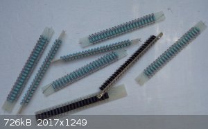
Some 100 MOhm sticks using VR37 resistors (I use them at 10kV/stick but I have tested each stick to 33 kVpk)
and some TVS strings for my 5kV oil burner ignition transformer. (7.something kV each stick)

I guess that a more up to date approach would be to use a string of smd resistors but I have no experience with smd resistors at high voltages and I'd
be concerned with possible flexing of pcb.
Adding inductance is a good idea, remember that inductance is also proportional to radius2
Transparent acrylic tube/pipe is not that much more expensive than pvc and allows inspection while in operation,
it has slightly less dielectric loss, higher m.p. and looks much prettier.
P.S. The competition https://www.youtube.com/watch?v=b-Gs81_-_aU
[Edited on 12-12-2018 by Sulaiman]
wg48 - 13-12-2018 at 10:28
Sulaiman: Thanks for the comments. As it happens my diodes are about 5mA max continuous current. Limiting the output current to that with resistors
would be the simplest, most robust and safest method but would result in a high impedance HT supply. As I previously explained I want to limit the
short circuit current to the surge current rating which 0.5A. Actually as only half the output current flows through the last diode so I can limit
the short circuit current to twice that amount. See attached snip of the spec. More precisely I will limit the short circuit to the I^2.t of the
surge current. The driving supply is current limited to 1mA.
The total charge available at the output of is only 11.8 uC. that’s just about 12uA flowing for 1s or for the half sine wave at 50Hz that would be
1.2mA for 10ms. Much smaller than the max surge current.
A quick calculation suggests with a duration of about 1us and a current 12A is less the I^2.t value of the surge current (heating effect), that
would require only 4kohms, I may add a much large resistance when demonstrating it to children for safety reasons.
A transparent tube would be cool as its principally intended for demonstrations to my nephews children. Doing my part to groom future Mad Science
members LOL
PS: The Van der Graaf generator was excellent and is safe for children. If I find a cheap ball/globe I will make one for the children.

Sulaiman - 13-12-2018 at 12:15
If you use the resistor and/or inductor between the multiplier and topload you can protect the diodes whilst also allowing the charge stored on the
topload to give impressive discharge sparks, with 'safe' current limiting otherwise.
If demonstrating to children / public then you will have to take into consideration that the resistors that I pointed to have a commercial rating of
3500V each,
but their 'safety critical' rating is only 125V each.
So a diy inductor can have less legal liability than a string of commercial resistors.
